Microreactors in Organic Chemistry and Catalysis, Second Edition (2013)
1. Properties and Use of Microreactors
1.3. Fluid Flow and Delivery Regimes
1.3.1 Fluid Flow
Flow in microreactors is typically characterized by a low Reynolds number ![]() . The Reynolds number is a dimensionless number that describes the ratio of inertial forces to viscous forces and is calculated by
. The Reynolds number is a dimensionless number that describes the ratio of inertial forces to viscous forces and is calculated by
(1.1) ![]()
where L is the characteristic length, ![]() is the fluid velocity,
is the fluid velocity, ![]() is the fluid density, and
is the fluid density, and ![]() is the fluid viscosity. When viscous forces dominate, as it is typical within microreactors, fluid flow is laminar. The threshold at which transition from turbulent to laminar flow occurs is dependent on the geometry of ducts through which the fluid is flowing, but typically, in a smooth channel or capillary, transition occurs between Re value 2000 and 2500 [87, 88]. As a result, without the use of special structures or active mechanisms, there is little turbulence-based mixing, and mixing occurs mainly through diffusion. Fick's Law of diffusion says that where
is the fluid viscosity. When viscous forces dominate, as it is typical within microreactors, fluid flow is laminar. The threshold at which transition from turbulent to laminar flow occurs is dependent on the geometry of ducts through which the fluid is flowing, but typically, in a smooth channel or capillary, transition occurs between Re value 2000 and 2500 [87, 88]. As a result, without the use of special structures or active mechanisms, there is little turbulence-based mixing, and mixing occurs mainly through diffusion. Fick's Law of diffusion says that where ![]() is the particle density or concentration,
is the particle density or concentration, ![]() is the diffusion coefficient, and Δ is the Laplace operator, then, the diffusion flux,
is the diffusion coefficient, and Δ is the Laplace operator, then, the diffusion flux, ![]() , can be defined as
, can be defined as
(1.2) ![]()
The diffusion can be further described by the Schmidt number (![]() ), which is the ratio of kinematic viscosity or momentum diffusivity,
), which is the ratio of kinematic viscosity or momentum diffusivity, ![]() , to mass diffusivity as defined by
, to mass diffusivity as defined by
(1.3) ![]()
The Schmidt number is also a dimensionless number but is unrelated to the geometry of the microchannel or capillary. As such, it is a characteristic of the liquid and can be used to determine how diffusion will occur within a certain liquid. Additionally, the rate of mass diffusion can be compared to the advection of a liquid within a microreactor via the Peclet number (![]() )
)
(1.4) ![]()
This number is a measure of the importance of advection in relation to diffusion. As the Peclet number increases so does the dominance of flow forces over that of molecular diffusion with regard to mixing. This number is, therefore, important in determining the conditions in which diffusion is the primary mixing method [89].
To demonstrate how advantageous working at a microscale can be, consider an initially very small spot of tracer in a resting solution [89]. The time (![]() ) taken by this spot to spread over a distance
) taken by this spot to spread over a distance ![]() can be estimated as
can be estimated as
(1.5) ![]()
This means that for reactions limited by diffusion, reaction time is proportional to the square of the rate limiting distance. Therefore, a reaction in a 10 cm flask could take 1 000 000 times less if undertaken in a 100 μm diameter microreactor. Dramatically reduced reaction times have, arguably, been the most potent driving force behind research in microreactor technology.
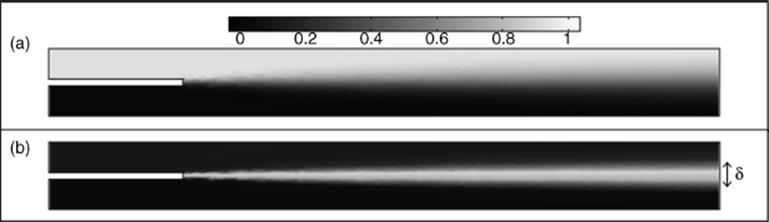
Figure 1.10 demonstrates the spreading of the “front” between two streams. The width of this front, δ, increases through diffusion over time as the fluids travel down the channel [89]. This width can be approximated using
(1.6) ![]()
If the width of the front is set to the width of the channel then the time it takes to mix diffusively in a microchannel can be determined.
Figure 1.10 Diffusive mixing in a square cross-sectional (side 500 μm) channel. (a) Two streams of water (colored to indicate the ratio of liquid one to liquid two, 1 on the scale indicating purely liquid one) running at 1 m/s in parallel to each other with mixing through diffusion only (b) Same simulation (as a) highlighting the region of diffusive mixing or “front” between the two fluids, in this case the lighter region indicates where diffusive mixing has occurred. The width of the front, δ, is indicated. Source: Both images obtained via COMSOL Multiphysics® simulation.
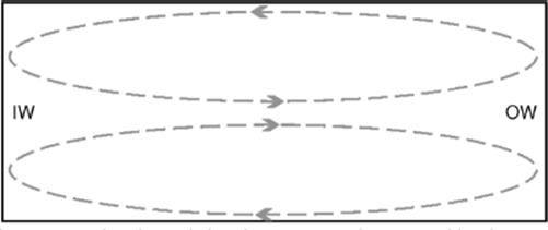
Although the limited levels of mixing in microchannels can be advantageous, sometimes greater levels of mixing are required. There are ways to encourage non-diffusion-based mixing to occur within a microchannel such as introducing an obstacle to induce turbulence-based mixing. An obstacle can cause turbulent flow as it can drastically lower the laminar flow transition threshold (into the region of Re 100 [90]). Adding turns to a channel can also initiate greater levels of mixing. In an enclosed rectangular channel, as fluid travels around a curve at appropriate flow rates, vortices are set up in the upper and lower halves of the channel; these are called Dean vortices (Figure 1.11).
Figure 1.11 Cross section of a turning rectangular channel showing Dean vortices caused by the turn. These Dean vortices can be advantageous, for example, in mixing or particle sorting. IW is the inner wall of the turn and OW is the outer wall.
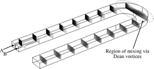
These Dean vortices will cause mixing but only across the width of the channel, not from top to bottom (Figure 1.12). (For further information about microreactor mixing see Section 1.3.3.)
Figure 1.12 Two parallel streams of water, A and B, (flowing at 3 m/s) are mixed via Dean vortices in a turn. Mixing before the turn is mostly by diffusion. Source: Image obtained via COMSOL Multiphysics® simulation.
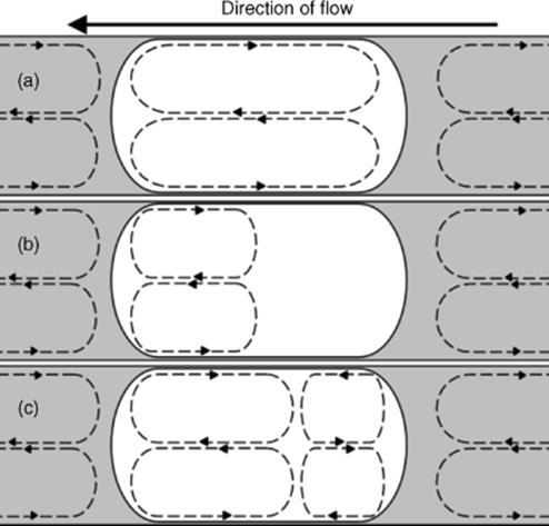
While fluid flow is often continuous and laminar, other regimes exist, such as, for example, in segmented flow. Here, immiscible fluids, or phases, are configured to provide contiguous “trains” of fluid “segments” or “packets” (see also Section 4.3). The flow within these fluid segments may be configured to be such that there occurs an internal vortex that causes rapid mixing within segment contents (Figure 1.13) and counters the lack of mixing normally characteristic of microscale fluid flow [91–94]. This fluid flow regime depends on the absolute velocity of the fluids, the fluid viscosities, their interfacial tension, and the geometry of the channels [95]. Adjacent contiguous segments may enjoy a highly dynamic fluidic interface providing many opportunities for novel interfacial chemical and other reactions. This internal vortex and interpacket dynamic interface may be readily switched to laminar flow (within packets) by simple modulation of the duct cross-sectional geometry, thereby changing the three-dimensional format of the individual fluid packets. Thus, dramatic alterations in mixing and mass transfer may be programmed within a given microreactor circuit configuration. The use of such solvent droplets resulting from controlled segmented flow has been proposed as individual nanoliter-scale reactors for organic synthesis [40, 41]. Fluid flow segmentation may be generated for a wide range of immiscible fluid matrices.
Figure 1.13 Internal circulations (indicated by the dashed lines) within segmented flow segments. Segments are white; continuous phase is the gray area. (a) Circulation over the whole length of the segment. This occurs within liquid segments suspended in an air continuous phase. (b) In a liquid–liquid system, circulation occurs at the front of the segment. The volume fraction of the circulation zone is dependent on certain parameters. Higher segment velocities increase the volume fraction of the circulation. This circulation zone can also be increased by using a lower viscosity continuous phase. Low interfacial tension also increases the size. High interfacial tension and viscosity can lead to no circulation at all. (c) At high segment velocities, counter-rotating circulation can be initiated towards the rear of the segment. Circulation zones are always set up in the continuous phase between the segments, irrespective of the other parameters [96].
Fluid packets may (i) contain particulates, including solid support beads, catalysts, and separations media, (ii) be subject to sequential additional reagent delivery through tributary ducts and channel injectors, (iii) be caused to split and/or coalesce, and (iv) be provided with individual identity through the provision of addressable molecular photonic and other codes. Segmented fluid packets as shown in Figures 1.13 and 1.17 may therefore be considered as “test tubes on the move” that are, for instance, transferred seamlessly from one functional high-throughput screening operation to another. The fluid packet format, for example, segmented by inert perfluorinated fluids, can be combined with interpacket liquid–liquid or solid-phase extractions [97] and microchannel contactor functions, enabling many possibilities for compound transfer between the different solvent streams of hyphenated functional processes. Collectively, these tools pose a radically different opportunity for synthesis, assay, and characterization procedures to traditional high-throughput screening operations such as in microtiter plate technology, storage, and information handling. This new platform paradigm with its inherent opportunities requires exploration through experimentation and modeling. For example, in a gas–liquid carbonylative coupling reaction, an annular flow regime was employed to generate a high interfacial surface area, where a thin film of liquid was forced to the wall surfaces of a microreactor (5 m length, 75 μl capacity) by carbon monoxide gas flow through the center [98].
The laminar stationary flow of an incompressible viscous liquid through cylindrical tubes can be described by Poiseuille's law. This description was later extended to turbulent flow. Flowing patterns of two immiscible phases are more complex in microcapillaries. Various patterns of liquid–liquid flow are described in more detail in Section 4.3, while liquid–gas flow and related applications are discussed in Section 4.4.
1.3.2 Fluid Delivery
1. Displacement: Hydrodynamic pumping has been the main method of fluid delivery generally used in microreactor systems till date. Hydrodynamic pumping usually employs the use of macro- or microscale peristaltic or positive displacement pumps [99–101]. High pressures can be obtained, as well as aggressive solvents are used. However, peristaltic pumps suffer from fluid-flow fluctuations at slow flow rates, and syringe pumps require carefully engineered changeover or refill mechanisms when used in long-duration, continuous-flow synthesis schemes.
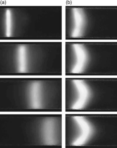
2. Electro-osmotic Flow (EOF): Fluid pumping in capillary-scale devices and systems may be readily enabled under certain conditions by electrokinetic flow that has the advantage that low levels of hydrodynamic dispersion are observed [102–104]. A detailed theoretical consideration of chemical reactions in microreactors under electro-osmotic and electrophoretic control has been described in the literature [105] (Figure 1.14). To enable EOF, electrodes are usually placed in reservoirs and voltage is applied, most preferably under computer control, with the magnitude of the voltage being a function of several factors including reactor geometry. Electro-osmotic flow pumping has been demonstrated in capillary-based flow reactors incorporating solid-supported reagents and catalysts [106, 107]. Further, an array of parallel microreactors, packed with silica-supported sulfuric acid, was operated under EOF to produce several tetrahydropyranyl ethers, thus demonstrating arithmetic scale out of EOF pumped microreactors [108]. However, EOF does place certain requirements on the microreactor design and surface properties of the constructional materials used. As an additional restriction, not every reaction can be performed in an electrical field as electrochemical side reactions can occur.
3. Centrifugal: Centrifugal forces have for some time been harnessed for the controlled propulsion of reagents in spinning disk microreactors [109]. This mechanism has also been used to control the elution, mixing, and incubation of reagents within enclosed reaction capillaries on rotating-disc platforms [110]. This represents a very innovative approach to chemical synthesis since the technique makes use of both hardware and software systems already developed for a mass-produced commodity. Additionally, the use of centrifugal forces provides an elegant way in which these can be used in combination with hydrophobic, the so-called burst valves to control fluid flow and incubation regimes.
Figure 1.14 Image sequences showing the nature of electro-osmotic flow (a) as compared to pressure-driven flow (b) in a 200 μm id circular cross-section capillary. The transport of the photo-injected cross-stream fluorescent markers illustrates: (a) the plug-like velocity profile characteristic of electro-osmotic flows, and (b) the parabolic velocity profile characteristic of pressure-driven flows. These images were obtained using caged-fluorescence imaging. Source: Image from Figure 1, Ref. [111] with kind permission from Springer Science and Business Media.
1.3.3 Mixing Mechanisms
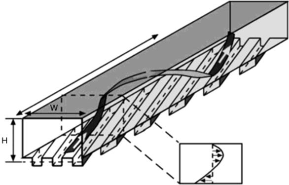
Microreactors are usually characterized by geometries with a low Reynolds number. In such capillary-scale ducts, laminar flow is dominant, and mixing relies essentially on diffusion unless special measures are taken, such as to cause turbulence or reduce diffusion time. Equally, laminar flow may be exploited such that laminar flow streams moving in parallel may contain reagents, which are caused to interact by careful control of the flow rate and variations in the microreactor geometry. A range of passive and active techniques to induce mixing include (i) complex geometries within microfluidic manifolds to cause repeated fluid twisting and flattening [112], (ii) acoustic streaming [113], (iii) resonant diaphragms, and (iv) acoustic cavitation microstreaming [114, 115]. Passive techniques such as split and recombine suffer from the requirement that fluids must usually be in a state of flow, whereas active methodologies enable mixing where there is no flow, such as in microwell reactors and under temporary stopped-flow conditions in microchannel reactors. A variant on this is a stopped-flow, batch-mode technique and has been employed to induce mixing on a centrifugal platform [116]. Not dissimilarly, pulsed flow in a microchannel has also been shown to be effective at causing accelerated mixing [117] and is dependent on several factors including the Strouhal number, the Peclet number, phase difference, pulse-to-volume ratio, and microchannel geometry. Microfabricated geometries within the microreactor design and which split and recombine fluids have been shown to cause multilamination and thus reduced diffusion distances [118–120]. Chaotic advection may also be caused by channels that contain integral staggered, serial, asymmetric rib-like structures [121] or are three-dimensionally twisted [122] (Figure 1.15). Active mechanisms for mixing based on energized, ultrasonically induced transport have been demonstrated [123]. An interesting form of rapid micromixing may also be achieved in liquid–liquid multiphase flow microreactors where within serial contiguous fluid packets there exists an internal vortex flow that counters the laminar flow profile normally characteristic of low Reynolds number geometries [96, 124].
Figure 1.15 Advection caused by integral structures. A schematic diagram of a microchannel with square grooves in the bottom wall. Below the channel to the right, the average flow profile in the cross section is drawn schematically. The ribbon indicates schematically a typical helical streamline in the channel. Source: Adapted with permission from Ref. [125]. Copyright 2002 American Chemical Society.