Microreactors in Organic Chemistry and Catalysis, Second Edition (2013)
8. Liquid–Liquid Biphasic Reactions
8.5. Surface–Liquid and Liquid–Liquid Interaction
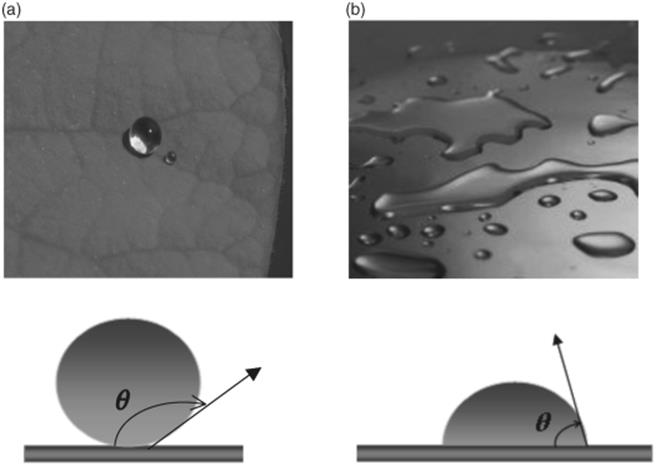
When cohesive forces of a liquid exceed the attractive forces between the liquid and the surface (adhesive forces), a high surface tension is formed resulting in a drop of liquid on the surface. On the other hand, when the adhesive forces dominate the cohesive forces, a low surface tension forms and the liquid will spread out over and wet the surface. The extent of contraction or spreading of the liquid depends on the strength of surface tension or, in other words, the wetting property of the surface and liquid. The degree of wetting can be expressed with the contact angle θ between the surface and the liquid. For example, a drop of water on a hydrophobic (nonwetting) surface would have a large contact angle going toward 180°, whereas the contact angle is small, approaching 0, when the water spreads on a hydrophilic surface (wetting) [15] (Figure 8.5).
Figure 8.5 Wetting versus nonwetting. (a) Water drop on a lotus leaf with hydrophobic surface leading to a large contact angle. Source: Lotus Image by Billy Bates, web address: (www.Victoria-Adventure.org). (b) Water drop on a glass surface with hydrophilic properties leading to a small contact angle. Source: Water drops on colored surface photo, photo Publisher: Creatas, Image reference: CR15206048, web address: (http://www.inmagine.com/liquid-in-motion-photos/creatas-cr15206-40).
Accordingly, on a surface with a medium hydrophobic property, the interface boundary of oil and water mixture, for instance, will contact the wall surface forming a point between the interface and the surface. The relation between the surface tension and the two liquids can be expressed by Young's equation, where ![]() is the interface tension between oil and water, while
is the interface tension between oil and water, while ![]() is the surface tension between the channel walls and the two phases [14].
is the surface tension between the channel walls and the two phases [14].
![]()
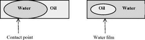
The effect of surface tension in a microchannel with same wetting property has on a flow of oil–water will result in a segmented flow pattern given the fact that oil has some wetting properties to the surface (Figure 8.6). The oil spreads through the channel material while the water forms segments that fill the channel diameter. In this case, the surface tension between the channel surface and the water has to be higher than the interface tension between the water and oil. If the interfacial tension between oil and water is higher than that between the water and surface, the use of surfactants, for example, can help reduce the interfacial tension. However, the surface tension between the two phases should be high enough to maintain the shape of the segments and avoid their destruction caused by the shear stress between them. In contrast, the interface boundary of oil and water mixture on a hydrophilic surface does not form a contact point, as a result of water phase spreading over the surface forming a film that separates the oil phase from the wall forming monodisperse oil droplets.
Figure 8.6 (a) Segmented flow of oil and water in a channel with a medium hydrophobic properties – the interface boundary and the channel surface are in contact and (b) droplet flow of oil and water in a channel with hydrophilic properties – the interface boundary and the channel surface are not in contact.
In the case where both liquids partially and equally wet the surface channel, the interface boundary takes irregular shapes, affecting the reproducibility of flow patterns. This demonstrates the direct effect which surface tension has on shaping the flow pattern of liquid–liquid systems. Hence, it is important to have control over the wetting properties in order to maintain regular flow patterns. Control can be easily achieved by treatment of the channel surface rather than varying the properties of the liquids. For example, microchannels made from certain polymers can be hydrophobic such as poly(methyl methacrylate) (PMMA), making it difficult to flow water through. Since the functional groups on these polymers are causing the hydrophobic character, one solution would be to treat the surface with UV light causing the polymer to break and therefore change the critical surface tension. On the other hand, hydrophilic surfaces such as glass or silicon can be turned into a hydrophobic surface by silanization. In this method, the free hydroxyl groups of the glass surface are deactivated by the coupling reaction with silanes leading to a nonwetting surface [15–17].
An alternative way of obtaining control over wetting properties is the use of surfactants to alter the properties of the liquid phases. Dreyfus et al. [18] investigated the effect which surfactants have on the flow pattern of an immiscible mixture of water and tetradecane on glass and silicon microchannels with three inlets as shown in Figure 8.7. When the surfactant concentration is higher than the critical micellar concentration, a complete wetting with respect to oil is achieved and the surface becomes completely hydrophobic. Initially, an experiment was conducted in which water and oil were injected into a microchannel through the three inlet ports, the water from the two side inlets (A and C as shown in Figure 8.7) and the oil from the central inlet (B) in a range of different flow rate ratios, followed by the inverse of the flow order. From that, a flow pattern map was obtained as shown in Figure 8.7. In the case where oil is injected from the central inlet at high flow rates, well defined and separated aqueous droplets were obtained and carried through the wetting oil flow as shown in the map. As the flow rate of oil decreases, the aqueous drops begin to extend in length and connect in forming a pearl necklace like flow. Increasing the flow rate of water results in its spreading in stratified manner as the velocity forces dominate the interfacial one. The oil flow in this case either forms a pear-like drop flow when it is at low flow rate or a stratified oil stream at high flow rate. The inlet junction has an influence on the flow pattern regime as well. To prove this, water flow was introduced from the central inlet and the oil from the two external inlets. Under conditions of high flow rates, similar flow patterns were observed as those shown in Figure 8.8 but in a reverse manner. Well-defined aqueous droplets were attained at high water flow rate combined with low oil flow rate and no pear-shaped droplets were observed. In addition, when both oil and water were introduced at high flow rate, the oil spreads over the channel walls while the aqueous stream flows in between. This clearly demonstrates that the formation of droplets, segmented or parallel flow does not only depend on the surface and interfacial forces but also on other factors such as inlet geometry and flow rate. Depending on the conditions, these factors could either generate instabilities at the liquid–liquid interface leading to monodisperse segments or stabilize it to form stratified flow patterns.
Figure 8.7 Various possible flow patterns in hydrophobic media using a cross inlet junction. Source: Reprinted Figure 3 with permission from Ref. [18]. Copyright 2003 by the American Physical Society.
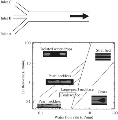
Figure 8.8 Dynamic process leading to drop formation of water segments in a main stream of oil flow with internal vortex circulation in each phase segment.
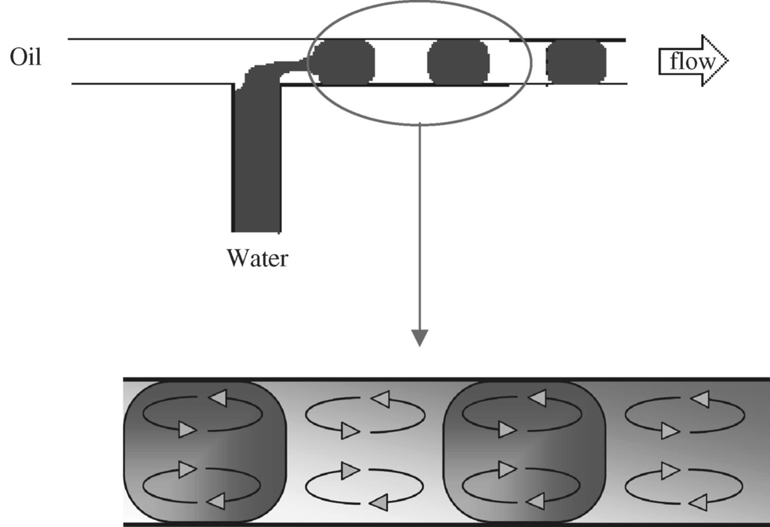
Droplet and segmented flow are generated at the inlet section because of the build up of pressure. The build up of pressure is a result of increased resistance of the water flow emerging from the inlet against the oil flow. This results in an interfacial instability that favors the interfacial area of the emerging flow head to increase through the mechanism of pinching, leading a segment. As the water segment begins to detach itself from the main water flow at the inlet, a tail at the back of the segment attached to the flow forms. The tail breaks eventually as the segment is pulled away by the oil flow to separate the segment from the main flow.
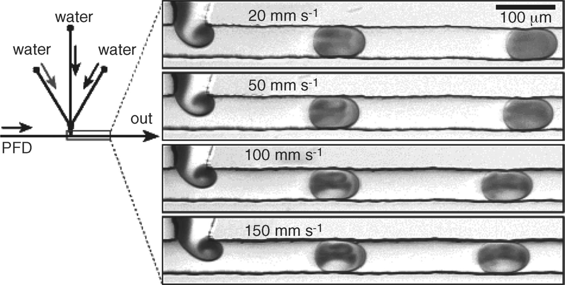
The interaction between the segment and the channel wall causes a shear stress due to the adhesive forces. This shear results in velocity streams in a straightened manner, from the end of the segment to the start in the direction of the flow. As the flow stream approaches the interface boundary, diversion of the stream occurs causing internal vortices inside the segment that are localized in the front and back parts of the segment. One complete cycle of recirculation occurs when the segment has traveled its length. Factors such as the segment size and the distance traveled by the segment affect the rate of internal mixing. Shorter segments have shorter mixing distances and, hence, the mixing is achieved in less time as shown clearly from the microphotographs produced by Ismagilov et al. [19] in their studies on the formation and mixing of droplets. These microphotographs (Figure 8.9) show three aqueous streams combined in a PDMS (polydimethylsiloxane) microchannel; two aqueous streams were separated in the middle by a third stream while continuously segmented into a flow of immiscible fluorinated solvent (PFD, perfluorodecalin). The reagents were mixed inside the segments while transported by the carrier PFD. To help the visualization of mixing inside the aqueous segments, one of the main aqueous streams was colored red using an inorganic iron complex while keeping the other streams colorless. The faster the recirculation, the faster is the mixing as the red color is distributed evenly around the segment faster. The longer the segment length, the longer it takes for the red color to distribute equally as illustrated in the microphotograph for the larger aqueous segments. In contrast, the experiment without the presence of carrier flow PDF shows laminar flow behavior as the aqueous mixture is not segmented and no circulation is generated.
Figure 8.9 Microphotographs illustrating weak dependence of periods, length of plugs, and flow patterns inside plugs on total flow velocity. Source: By courtesy of the American Chemical Society [19].
As discussed previously, Dreyfus et al. [18] found that a stratified flow can be generated when both phases are introduced at high flow rates. The formation of a stable, stratified flow depends on the conditions at the inlet junction as well as the channel, affected by the inlet geometry, liquid properties, and the flow rate. As the flow rate of both phases increases, the viscous forces dominate the capillary number (Ca) and the interfacial instability reduces as the pressure fluctuation minimizes. One observes the stratification of both phases. Once the parallel streams are formed, mixing occurs via diffusion only between the two phases through the interface and no internal circulation is generated. However, stabilizing parallel flow is not as easy as the formation of droplets or segmented flow, because the interfacial stability is very sensitive to velocity as uneven velocities at the interface produces vortices leading to turbulent flow. This behavior is known as Kelvin–Helmholtz instability [20].