Microreactors in Organic Chemistry and Catalysis, Second Edition (2013)
9. Gas–Liquid Reactions
9.2. Contacting Principles and Microreactors
9.2.1 Contacting with Continuous Phases
One way to contact a gas and a liquid is to have both phases continuous, “side by side,” that is, the fluids are not dispersed into each other. This has the benefit of a known well-defined and stationary interface. “Polydispersity” in hydrodynamic characteristics is absent (for intrinsic reasons), as given typically for a swarm of bubbles flowing in a liquid (e.g., in a bubble column or tube reactor) and also no “aging” like coalescence of bubbles. Different from disperse systems, in continuous systems the gas phase does not need to be distributed, but only the liquid phase. Phase separation is facile since the phases are never intermixed. Owing to the known interfaces and usually also defined liquid and gas layers numbering up is a valuable concept, as the addition of more channels goes along with the replication of the hydrodynamic conditions. This, however, will only be efficient if flow equipartition is on a high standard and that wetting will be the same for all microchannels. Indeed, continuous-phase microreactors comprise the first reported scaled out gas–liquid devices which are pilot-scale falling film and annular flow microreactors. Two-phase contactors, as their disperse counterparts, generally need visual control to check the hydrodynamics via transparency of the whole device or inspection windows, which makes construction more complex and limits pressure operation.
9.2.1.1 Falling Film Microreactor
The falling film principle utilizes the wetting of a surface by a liquid stream, governed by gravity force, which thus spreads to form an expanded thin film (Figure 9.1a); a concept known from macroscale contactors. Typical films have a thickness of a few tens to a few hundred micrometers [4, 26, 41].
Figure 9.1 (a) Principle to generate a falling film on a structured plate with channels. (b) Falling film microreactor, FFMR-Standard, laboratory version up to 1 l/h. (c) STACK-1x-FFMR-LAB up to 0.1 l/h. Source: By courtesy of IMM.
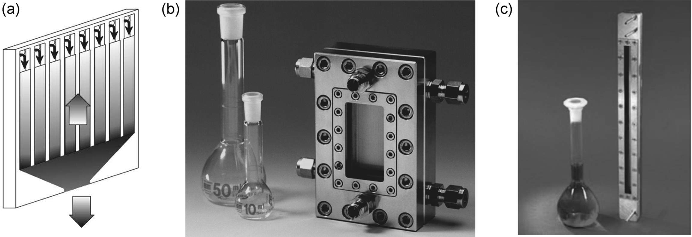
In one version realized, a flow restrictor, typically a slit, creates pressure loss to improve liquid flow distribution from the incoming stream to the channels of a microstructured plate (see Figure 9.1b) [4, 26, 41]. The liquid streams are recollected via another slit at the end of the plate. The gas flow enters a large gas chamber, positioned above the microchannels, via a diffuser. Heat exchange is realized by integration of a minichannel heat exchanger, positioned in the rear of the reaction zone. An inspection window above the gas chamber allows to check the falling films. Furthermore, this enables to carry out photochemical gas/liquid reactions [42]. The slit and the gas chamber with its two diffusers are made by micro electro discharge machining (μEDM). The microchannels are etched in the plate. The heat exchange channels are manufactured by micromilling.
Another, newer version of laboratory falling film microreactor is brazed, 25 cm long microreactor/contactor with the nomination STACK-1-FFMR-LAB (see Figure 9.1c). This falling film microreactor consists of five 1200 × 400 μm2 channels, with a 4 mm thick gas chamber, and has inspection window for easier reaction/process monitoring. Brazing technology with no seals allows for applications with higher pressure. The reaction plate is, however, durably embedded in the housing and changing the channel structures is not possible in this version. Mass transfer characteristics much different than with the FFMR-Standard are observed for this microcontactor [43].
Scaled out versions of the laboratory falling film microreactors discussed above were made, with about 10 times larger channel surface, which roughly means 10 times larger gas–liquid interface [44]. This was done in three ways. One cylindrical falling film concept relies largely on internal numbering up, with an increase in the number of microchannels as compared to the laboratory tool by more compact arrangement on a cylindrical metal block (Figure 9.2). This pilot device has outer dimensions, which hardly exceed the laboratory tool. For practical reasons, that is, to facilitate microfabrication, the length of the microchannels is slightly larger in the cylindrical device, so that this is not a pure numbering up approach. Another pilot falling film device relies on classical scale-up, with both the channel width and length being enlarged by a factor of 3.3, which gives 10 times larger surface (see Figure 9.2). While the laboratory tool has an upper flow limit of about 1 l/h, the two pilot reactors come to about 10 l/h.
Figure 9.2 (a) Numbered up, “Cylindrical,” and scaled-up, (b) “large,” (laboratory version in front), (c) open and closed “STACK-1x-FFMR-LARGE” falling film microreactors. Source: By courtesy of IMM.
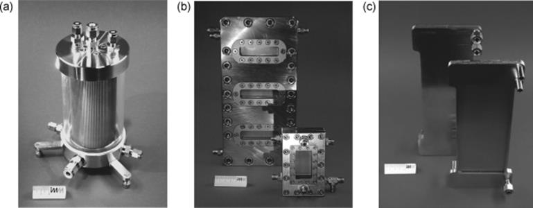
Scaled up version of brazed falling film microreactor have also been designed (Figure 9.2c). In this version, interfacial area is equal to this of STACK- 1x-FFMR-LAB, the only differences are in 10 times increased number of channels and the absence of an inspection window.
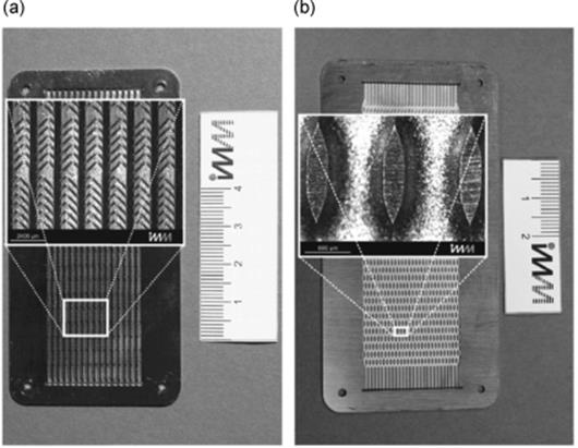
Further enhancement in falling film microreactor performance is achieved through an internal structuring [45, 46]. The investigated microreactor is equipped with structured channels to enhance the mass transfer within the liquid phase (Figure 9.3). Therewith, by properly chosen channel geometry the conversion can be increased by up to 42% compared to the falling film microreactor with straight channels. Hence, using an optimal reaction plate it is possible to more than double the flow rate, without any loss in conversion.
Figure 9.3 Photographs of the structured reaction plates. The enlargements within the pictures show the structures in detail. (a) Reaction plate with grooves. (b) Reaction plate with fins. Source: By courtesy of Elsevier.
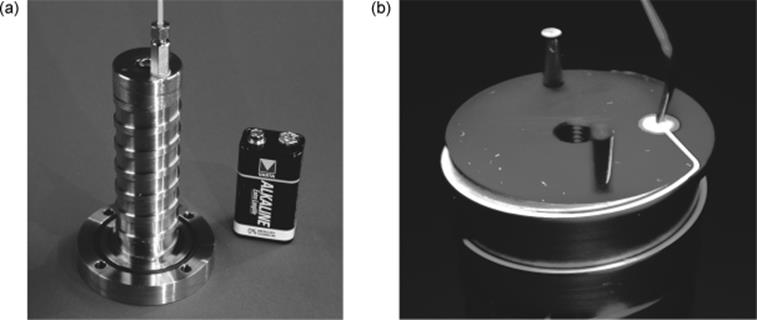
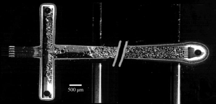
The laboratory falling film microreactor is limited in residence time [47]. About 1 min is the maximum practical time. An extension to reaction times of several minutes can only be reached by either using vertical reaction channel plates of several 10 cm length exceeding even 1 m, which on its own is neither practical nor a smart solution, or decreasing the falling angle to have less impact of gravity. A new, more compact design based on a helical guiding of the liquid film combines both approaches (Figure 9.4). Owing to the winding of the channel, a large length is realized on small footprint and the channel declines at small falling angle. This is done, however, at the expense of overall throughput so that this device is restricted to analytical investigations.
Figure 9.4 Helical falling film microreactor (a). Flow of the liquid in the helical microchannel, visualized by injection of a fluorescent tracer (b). Source: By courtesy of Elsevier and IMM [47].
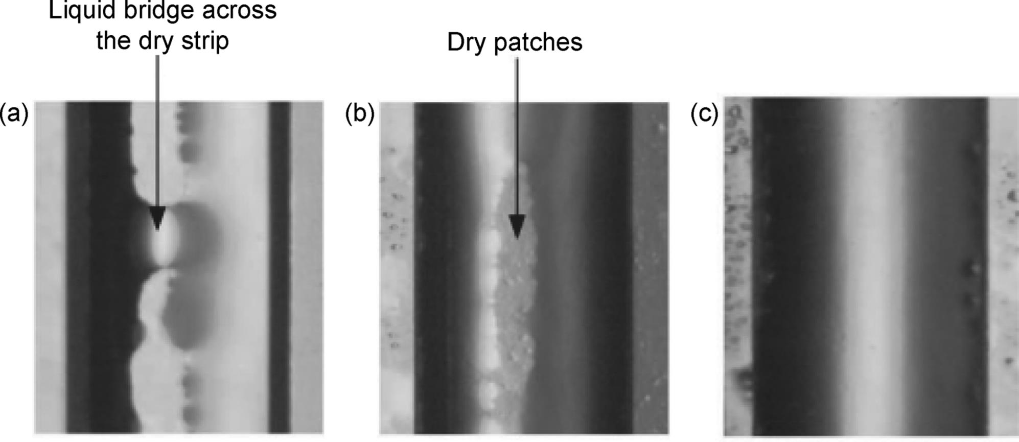
Flow pattern of liquid film of a falling film microreactor was investigated using high-speed CCD camera [48]. Three flow regimes were identified as “corner rivulet flow,” “falling film flow with dry patches,” and “complete falling film flow” when liquid flow rate increased gradually (Figure 9.5). The desirable regime to perform gas–liquid absorption is the “complete falling film flow.”
Figure 9.5 Flow pattern of a falling film in falling film microreactor (microchannel cross-section: 1000 μm × 300 μm; liquid: 110 ppm SLS solution). (a) Corner rivulet flow (QL = 2 ml/min); (b) falling film flow with dry patches (QL = 3 ml/min); (c) complete falling liquid film (QL = 3.9 ml/min) [48]. Source: Reprinted with permission from John Wiley and Sons.
Initially, taper cone-shaped devices were made from aluminum by computerized numerically controlled (CNC) turning as manufacturing technique using a lathe [47]. These devices are easily amenable to inspection of the complete fluidic path. The empty channel surface and the liquid surface of the filled channel were accessible by white light interferometry. Using n-butanol as liquid flowing in microchannels of 100 μm × 300 μm cross-section, a complete filling of the microchannels without any flooding or undesired wetting of liquid at the walls of the cylinder next to the channel was achieved.
Since cuts through the taper cone devices showed that structural quality and surface roughness of the microchannels need to be improved, the design of the helical falling film microreactor was changed and a microstructured cylinder was made of stainless steel, instead of the taper cone (see Figure 9.3a) [47]. The helical path was set to 7.5°. The channel width and depth is set to 300 and 100 μm, respectively. The diameter of the cylinder amounts to 24.3 mm. Three lengths of the helical path of 540, 1540, and 5390 mm (corresponding to a total device length of 70, 200, and 700 mm) were made to give residence times of 10, 30, and 105 min, respectively. The gas stream is guided through a cylindrical housing. The residence times of both helical devices, the microstructured taper cone and the cylinder, are about a factor of 50 higher than in the standard falling film microreactor [47]. Depending on the viscosity of the solvent, residence times from 3 min for methanol up to 22 min for octanol could be determined.
The housing consists of a capped stainless steel tube [47]. For high pressure experiments, a stainless steel housing can be used up to 50 bar at 20 °C. Additionally, the stainless steel tube can be replaced by a transparent PMMA housing. This allows a visual inspection of the microchannels in the case of low-pressure experiments (up to 5 bar).
To maximize the process intensification in the falling film microreactor, there is a need to characterize and investigate the design parameters of the reactor. In general, the major rate limiting steps occur on the liquid side. A realistic description of the liquid film is given by a so-called pseudo 3-D computational fluid dynamic (CFD) model [49]. It is shown that fabrication imprecisions of the investigated microchannels by 11% in channel width and 6% in channel depth has only a 2% impact on the reaction conversion. Moreover, a liquid flow mal distribution, in the parallel microchannels assembled on plate, with a relative standard deviation of 0.37 lowers the reaction conversion by about 2%. A reduction of gas chamber height slightly improves the conversion and gas phase mass transfer limitation can be overcome. Moreover, the material of the reactor plate has to provide sufficient wetability for the liquid falling film.
Principles of a falling film microreactor have been applied to other falling film microdevices where enhanced mass transfer is needed, such as a falling film microabsorber and a falling film micro evaporator [43, 50–52].
9.2.1.2 Continuous Contactor with Partly Overlapping Channels
Solute transfer can occur between immiscible phases each flowing in separate adjacent, but displaced microchannels, only having a small conduit at which the fluid interface is stable (partial overlap) [53, 54].
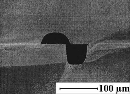
This concept of partly overlapping channels was realized by having one plate with a rectangular channel manufactured in silicon by sawing, covered by another plate with a semicircular channel made in glass by wet-chemical etching (Figure 9.6) [53, 54]. The glass/silicon plates are joined by anodic bonding. To ensure efficient mass transfer and to stabilize the interface, channel depth (i.e., the diffusion distance to the interface) should be about 100 μm and the channel opening should be about 20 μm [55]. A numbered up module was developed with 120 partly overlapping microchannels operating in parallel.
Figure 9.6 Scanning electron microscopy image through a continuous contactor with partly overlapping channels revealing reactangular and semicircular channels at adjacent, but displaced positions. Source: By courtesy of J. Shaw [53].
9.2.1.3 Mesh Microcontactor
Recent developments in the area of microengineered structures for chemical processing [24] made possible to manufacture meshes of various materials (i.e., steel, silicon nitride), by techniques such as standard mask lithography, or laser interference lithography [56, 57].
Thin meshes (50–200 μm thickness) with micron-range pore size can be obtained. These can be incorporated in the design of microdevices for processing at microscale and offer more flexibility to control the liquid film thickness and residence time as compared to falling-film microreactors where the contact between phases is direct. Microfabricated meshes combine the advantage of minimizing the resistance in the mesh with high porosity and regular patterned pore structure having at the same time good mechanical strength. Hence, they can provide improved performance as compared to membranes, particularly when the liquid wets the membrane/mesh.
A mesh microcontactor contains a microstructured plate with regular circular openings through which separate gas and liquid streams come into contact [58, 59]. Stability of the interface and prevention of breakthrough is achieved by adjusting the pressure. Gas–liquid operation requires a low gas flow through the microcontactor in order to achieve the necessary back pressure. Operation is generally possible also in stop-flow mode besides continuous flow.
The first realized mesh microcontactor was shaped to restrict dispersion of sequential samples delivered to and from the reaction zone (Figure 9.7) [58, 59]. A quadrant structure with manifold channel at outlet only and central inlet feed was chosen. Nickel is used for the mesh material because of its robustness, ease of fabrication by pattern plating, and its compatibility with a wide range of alkaline to neutral solutions. The mesh is inserted in an enclosure formed from glass and copper. The distance from the mesh to the chamber walls is 100 μm on each side. The reaction chamber volume for each phase is 100 μl. Milling was applied as manufacturing technique for the reactor parts. Nickel mesh fabrication involves photolithography and a two-stage electroplating method.
Figure 9.7 Nickel mesh. (a) Photograph of complete mesh showing frame and struts. (b) Scanning electron micrograph of mesh pores. (c) Assembled device. Source: By courtesy of the Royal Society of Chemistry [58].
Another membrane/mesh microcontactor is applied for stripping of volatile components from organic liquid solutions [60]. Membrane openings were manufactured by laser micromachining or photochemical etching. The maximum pore sizes were between 10 and 100 μm, and the open areas were in the range 8–30%. A photo of assembled device is shown in Figure 9.8.
Figure 9.8 Assembled gas–liquid contactor [60]. Source: By courtesy of Elsevier.
A polyacrylate mesh microreactor was also used for analysis of residence time distribution and phase holdup [61, 62]. Existence of hysteresis due to wetting characteristic of the mesh is observed and the liquid operating range was limited by the area of individual mesh types [61]. Uniform flow and residence time distributions are achievable through an analytical resistance network model [62].
9.2.1.4 Annular-Flow Microreactors
Annular-flow microreactors are generically similar in design to the Taylor-flow reactors, as both flow regimes can be realized in each of these devices. The (small) difference is that usually less attention is paid to the design of the mixing element for gas and liquid streams. No delicate bubble formation is needed, but rather a simple split into continuous gas and liquid streams. In the simplest version, just two holes enter in a series into a microchannel, with the liquid stream typically incoming first and the surrounding the next opening for the gas which gives a gaseous cylinder with a thin liquid shell. Further, the reaction channel is usually smaller than for Taylor-flow reactors, because annular-flow reactors are used for very fast reactions with high demands for heat transfer.
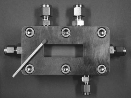
In one of the very early versions, a microreactor was composed of two plates and a block, made from a special steel, forming the conduits for gas and liquids and a single reaction microchannel, with one of the plates being transparent for visualizing the flow in the latter (Figure 9.9) [63, 64]. The reaction microchannel is cut in the bottom block and the block is highly polished to ensure gas tightness [16].
Figure 9.9 Schematic of the single-channel microreactor, used for fluorinations with elemental fluorine. Source: By courtesy of the Royal Society of Chemistry [63].
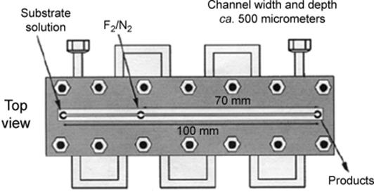
A coolant channel is guided through the metal block in a serpentine manner so that reactant and coolant flows are orthogonal [63]. A thermocouple measures the temperature at the product outlet. This microreactor was developed for the (very fast) fluorination reactions with elemental fluorine. Therefore, the surface of the microchannel was inactivated by exposure to increasing concentration of fluorine in nitrogen.
After the initial manufacture of a single-microchannel version [63], a numbered up (scale-out) three-channel microreactor followed later [64].
Another annular-flow concept was provided by the so-called dual-channel reactor with two parallel microchannels separated by a wall. In this way, four thin liquid layers in annular flow were created at once (Figure 9.10b) [65]. In front of this section, the liquid feed enters through a hole directed to the wall, while the two gas feeds point to the two reaction channels. Consequently, the liquid flow splits and a larger interface is created than given for single-channel guidance.
Figure 9.10 Schematic of the inlet section of the dual-channel microreactor (b) and SEM micrograph of a cut through the dual-channel section (a). Source: By courtesy of American Chemical Society [65].
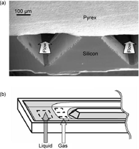
The dual-channel reactor was manufactured as silicon chip device, compressed between two plates, was made by photolithography and potassium hydroxide etching [65]. Silicon oxide was thermally grown on silicon and thin films of nickel were evaporated for passivation, because direct fluorination in this device was envisaged. Pyrex was bonded anodically to the modified microstructured silicon wafer (see Figure 9.10a).
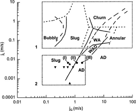
A flow-pattern map was derived for nitrogen–acetonitrile flows in the dual-channel microreactor [65]. Bubbly, slug, churn, and annular flows were found as well as wavy annular and wavy annular-dry flows with smaller region of stability (Figure 9.11).
Figure 9.11 Flow pattern map for the nitrogen–acetonitrile flow in the dual-channel microreactor. Annular flow; wavy annular flow (WA); wavy annular-dry flow, (WAD); slug flow; bubbly flow; annular-dry flow (AD). Transition lines for nitrogen–acetonitrile flows in a triangular channel (224 μm) (solid line). Transition lines for air–water flows in triangular channels (1.097 mm) (dashed lines). Region 2 presents flow conditions in the dual-channel reactor, (![]() ), with the acetonitrile–nitrogen system between the limits of channeling (I) and partially dried walls (III). Flow conditions in rectangular channels for a 32-channel reactor (150 μm) (
), with the acetonitrile–nitrogen system between the limits of channeling (I) and partially dried walls (III). Flow conditions in rectangular channels for a 32-channel reactor (150 μm) (![]() ), and single channel reactor (500 μm) (
), and single channel reactor (500 μm) (![]() ). Source: By courtesy of American Chemical Society [65].
). Source: By courtesy of American Chemical Society [65].
9.2.2 Contacting with Disperse Phases
Dispersions at micron-scale are usually made by merging gas and liquid streams in a mixing element and subsequent decay of the gas stream to a dispersion [29–40]. Mixing elements often have simple shapes such as a mixing tee (dual-feed: gas–liquid) or triple-feed (liquid–gas–liquid) arrangements. The dispersion is passed either in a microchannel (or many of these) or in a larger environment such as a chamber, which for example, provides volume to fill in porous material such as catalyst particle beds, foams, or artificial structures (microcolumn array). The mechanisms for bubble formation have not been investigated for all of the devices used for real-case applications, but according to fundamental microfluidic studies shear force or hydrodynamic instability plays a major role.
The different flow patterns largely resemble those known from flow in other continuous flow conduits as pipes, tubes, capillaries, and monoliths [29–40]. Bubbly flow, slug flow (Taylor flow), annular, and churn flow are found and a few more intermediate regimes between the ones mentioned. These comprise different gas–liquid configurations such as segmented flow (bubble-train), gas core with encompassing stable thin liquid film, which wets the channel wall, and dynamic wavy liquid films. In case of high gas contents, spray is created with small droplets in continuous gas phase [66, 67]. Most often, Taylor and annular flow were used in gas–liquid microreactor engineering, as these two patterns have stable and large known interfaces with good mixing and low axial dispersion. Similar to the falling film microreactors, inspection windows or, even better, totally transparent devices are almost a must, at least on a prototype and process development stage.
The feed of dispersive systems in many parallel microchannels is not trivial and mixed flow patterns and even drying of the channels were reported for the first-hour devices [66, 67]. Distributor design solutions for phase equipartition were proposed for some devices, for example, for mini-packed reactors [68–70].
9.2.2.1 Taylor-Flow Microreactors
Taylor-flow microreactors contain a dispersing mixing element for gas and liquid streams, typically of T- and Y-shape, followed by a reaction channel for the segmented gas–liquid flow, often of quite extended length, as the Taylor flow is dominant in typical flow-pattern maps [4, 26, 27]. In general, all Taylor-flow microreactors can induce other flow patterns as well those which were mentioned above.
In one version, Taylor flow microreactors comprised two types of mixer designs followed by a single microchannel (Figure 9.12) [71].
Figure 9.12 Design of a Taylor flow microreactor with feeds and mixing zone (left) and reaction channel and outlet (right). Please note that in the image an improved T-type mixer design is given, which differs somewhat from the one shown in Figure 9.10. Dimensions of the mixers are also given below and the reaction channel is 100 μm wide and 50 μm deep at a length of 2.2 cm length. The outer dimensions of this chip are 45 mm × 8 mm × 1.5 mm. Source: By courtesy of M. Warnier, Eindhoven University of Technology.
The gas feed is encompassed by two equal liquid inlets with differing contacting angle of the two liquid streams with respect to the gas stream and different contact region (“T-type and smooth”) (Figure 9.13) [71]. The flow was then introduced into a straight reaction channel in both mixers.
Figure 9.13 Design of two mixing units in Taylor flow microreactors used for achieving dispersed flow in a downstream channel (100 μm width × 50 μm depth, 2 cm length). L: liquid and G: gas. Source: By courtesy of Wiley-VCH Verlag GmbH [71].
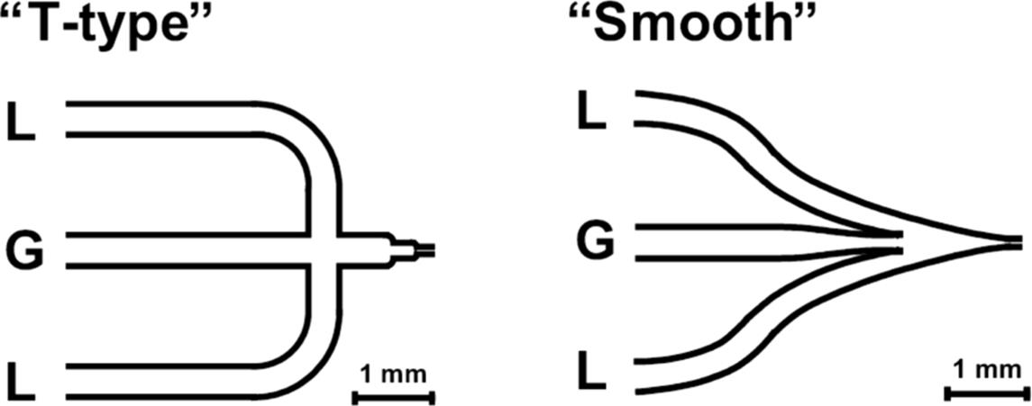
In the T-type mixer, channel width is decreased in two stages, thereby creating an intermediate bubble formation chamber, which has the function to assist in bubble rupture. The idea is to perform bubbles to a specific geometry [71]. Beside bubble rupture, another mode of bubble formation has also been observed. In the smooth mixer, the channel width reduction is performed in a continuous manner, that is, without any stages and edges. Here, gas and liquid flows enter into the reaction channel largely unchanged after initial hydrodynamic decay. The devices are constructed from two plates, which are irreversibly joined by anodic bonding. Microfabrication was achieved by means of deep reactive ion etching (DRIE) in borosilicate glass.
Using high-speed microscopy imaging, four main flow patterns were observed that are similar to those given in Figure 9.8 [71]. Slug flow, churn flow, and annular flow were found (see Figure 9.11). Bubbly flow was observed only initially at the channel entrance section, which then changed to slug flow because of pressure changes in the microchannel. As another kind of flow pattern, not shown in Figure 9.11, ring flow was observed which is similar to annular flow, but with irregularities of the inner gas core (Figure 9.14).
Figure 9.14 Flow patterns of nitrogen/water flows in microchannels of the Taylor flow microreactor given in Figure 9.9. The superficial gas (Ug) and superficial liquid velocities (Ul) are indicated. The channel has a rectangular cross-section of 100 μm × 50 μm. Source: By courtesy of Wiley-VCH Verlag GmbH [54].
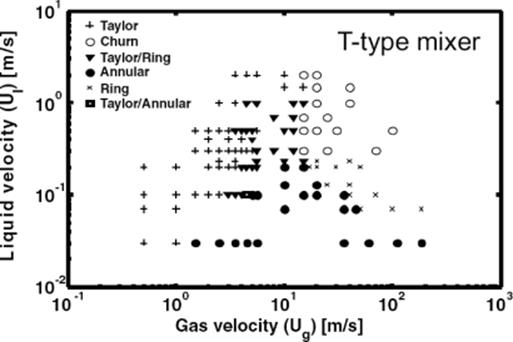
Using this information, flow-pattern maps were derived (Figure 9.15) [71]. These maps are schematically in accordance to prior findings of other groups for monoliths and resemble also the flow patterns measured for the micro bubble column as described below. A significant dependence of details of these flow patterns (e.g., for the transition from slug to churn flow and the transition from annular to ring flow) on the mixer structure was found. This comes from the high liquid and/or gas velocities used and inertia can no longer be neglected with respect to the surface tension.
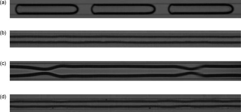
Figure 9.15 Flow patterns for the nitrogen/water system observed for the smooth mixer in the microchannel used at the TU/e. The images were recorded at the indicated superficial gas (Ug) and superficial liquid velocities (Ul). The channel has a rectangular cross-section of 100 μm × 50 μm. (a) Slug flow: (Ug = 0.5 m/s, Ul = 0.1 m/s); (b) annular flow: (Ug = 5.5 m/s, Ul = 0.07 m/s); (c) ring flow: (Ug = 20 m/s, Ul = 0.2 m/s); and (d) churn flow: (Ug = 50 m/s, Ul= 0.5 m/s). Source: By courtesy of Wiley-VCH Verlag GmbH [71].
The effect of fluid properties and wetting properties of the channel wall on the flow regime and flow pattern transition was studied [72]. For lower hydrophilicity of the channel surface, the transition boundaries of the slug flow to the slug-annular flow and the slug-annular flow to the annular flow shift to lower ReG/ReL (Figure 9.16). The effect of wettability on micro-fluidics in the surface tension-dominated zone was more apparent than that in the inertia-dominated zone. Both surface tension and viscosity of the liquid are influencing the flow pattern transitions.
Figure 9.16 Flow pattern for the nitrogen-ethanol system, for rectangular channels of 100 μm × 200 μm, transition from slug to annular and stratified (parallel) flow occurs for higher gas velocities and higher capillary number, where Ca = ULμL/σ, ReG = DHUG/γgReL = DHUL/γl [72]. Source: By courtesy of Elsevier.
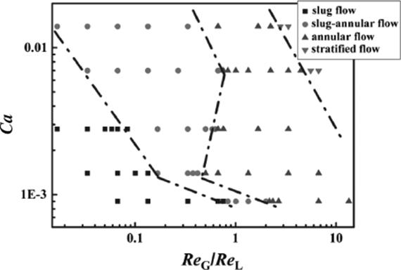
Figure 9.16 shows flow pattern for the nitrogen-ethanol system expressed as a relation of capillary number, which defines fluid properties, and Reynolds number of gas and liquid phases.
A universal transition prediction model of the transition capillary number as the functions of the Reynolds numbers of gas and liquid phases and the contact angle of the channel wall is formulated as
(9.1) ![]()
where a, b, and c are parameters, θ is the contact angle of fluid on the solid surface (degrees), ReG and ReL are Reynolds numbers for gas and liquid phase, respectively.
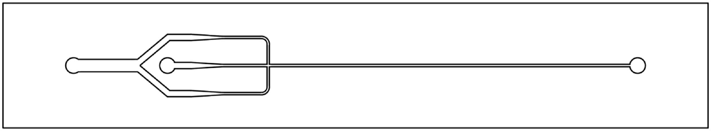
A transparent microchip reactor with triple mixing element (liquid–gas–liquid) was developed for photochemical gas–liquid synthesis [73]. The mixing element was fed from a liquid inlet port, which splits into two channels of equal passage which merge with a third channel, connected to a second port for gas feed. This triple-stream mixer is followed by a long serpentine channel passage that ends in a third outlet port. The channels were micromachined by direct laser lithography and wet-chemical etching in the bottom plate. The bottom plate was bonded thermally to a cover.
Similar to the numbered up Taylor-flow reactor, the “micro bubble column” achieved dispersion by an interdigital mixing element with many miniaturized mixing tees (Figures 9.17 and 9.18) [4, 26, 66, 67, 71, 74, 75]. This was one of the very early versions developed, which was commercialized later. The dispersion is guided in a microchannel array (for reaction) with exact positioning of each channel of the separate mixing element to the corresponding channel in the reaction array. This is similar for many other Taylor-flow microreactors, which, however, usually comprise only one mixing element with two (gas–liquid) or three (liquid–gas–liquid) feed channels connected to one reaction channel. Different from the microbubble column, made from steel and equipped with an inspection window, many other Taylor-flow microreactors are fully transparent, for example, made from glass, or with a whole transparent cover plate (silicon-glass).
Figure 9.17 Schematic of the “microbubble column,” a numbered up Taylor-flow microreactor with a mixing for each reaction channel (a) SEM micrograph of the mixing element, top view (b). L: liquid and G: gas. The small channels with the semicircular openings are the gas feed, the larger rectangular ones are for liquid feed. Source: By courtesy of VDI Verlag [66].
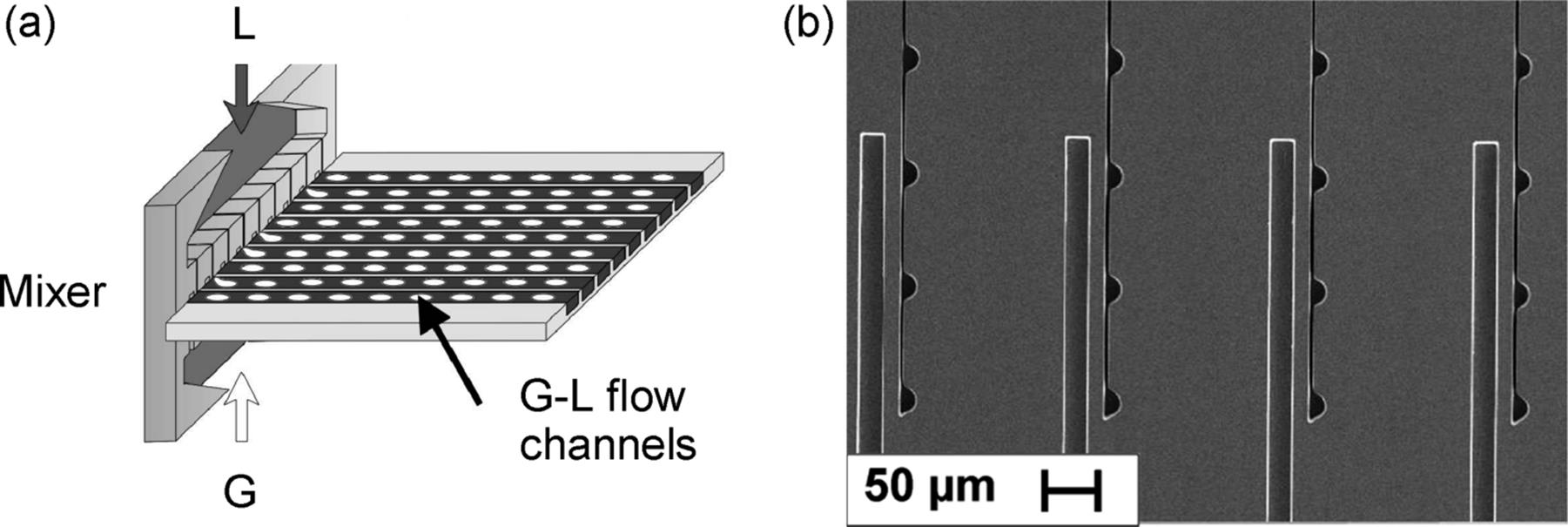
Figure 9.18 Microbubble column (redesigned version). Besides the two inlets for gas and liquid flows and the outlet for the dispersion, two further fluid connectors are there for the in- and out-coming heat exchange medium. Source: By courtesy of Wiley-VCH Verlag GmbH [71].
While the degree of numbering up of the micro bubble column is limited by the number of channels on one plate, a modular reactor was developed which contains a stack of microstructured plates. The construction encompasses five different assembly groups, a cylindrical inner housing, which encases the plate stack, two diffusers before and after, and a cylindrical outer shell with a flange [76] (see also Ref. [77]). The platelets were fabricated by thin-wire μEDM. This construction allows fast plate exchange, for example, only 15–30 min are necessary for cooling from 480 °C to ambient temperature [77]. Since no special inlet manifold was used, some degree of phase separation probably occurred, that is, some microchannels may have been filled only with liquid, while others comprise only gas.
9.2.2.2 Micromixer-Capillary/Tube Reactors
While the above mentioned Taylor-flow microreactors are integrated designs of dispersive mixing elements and attached reaction channels, the same type of arrangement can be realized more on a mesoscale by combining micromixers (as single tools) and capillaries or tubes (see Refs [78, 79] for a review on micromixers). Depending on the hydraulic diameter of the latter, the large variety in flow regimes may be lost and rather only bubbly flow and foams may be generated. Several issues are encountered while operating micromixers, for which the solution would require better understanding of the mixing inside. Some typical problems are connections and feedings, online process control, solid handling and clogging, and nature of the surfaces [24].
The most striking advantages of this concept are simplicity in approach and operation, as well as fast installation, since micromixers are commercially available at comparatively low cost, and ability to reach high productivity already with one device.
However, coalescence of the foam may occur, as surface forces are less dominant here due to the larger scale. In aqueous systems, this can be prevented by adding surfactants to lower surface tension. For organic solvents, there is no straightforward solution and only short-term contacting may be realized. In addition, the interface may be not as defined as for two-phase continuous and some of the disperse microreactors, with the exception of the foams that can be quite regular [80].
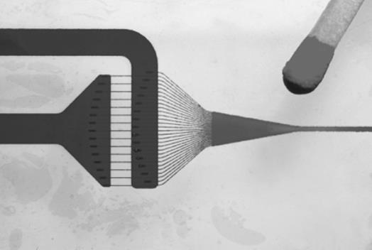
A large number of micromixers have been used, most often their design was not oriented on a special use for gas–liquid reactions, but rather on mixing of miscible liquids [78]. Interdigital micromixers comprise respective feed channel arrays that lead to an alternating arrangement of feed streams generating multilamellae flows, that is, mix by diffusion in the case of miscible liquids [81–83]. In the gas–liquid case considered here, multiple gas jets in a liquid medium are realized which decay to bubbles by hydrodynamic instability [84, 85]. Interdigital micromixers were manufactured as metal/stainless steel devices (Figure 9.19) [81] or as glass devices (Figure 9.20) [81].
Figure 9.19 High-pressure interdigital micromixer made of steel.
Figure 9.20 Flow focusing interdigital micromixer made of glass. Source: By courtesy of IMM.
Split–recombine micromixers with repeated physical separation of fluid streams by branching into separate channels and recombination of channels and streams perform also multilamination or, probably more correctly expressed, compartmentation of streams. By the reduction of diffusion distances mixing is promoted [86–88]. Owing to the low pressure loss of this mixing approach, relatively high flows can be realized. One split–recombine device was made of silicon with a series of fork-like channel segments and was tested, among other uses, also for gas–liquid contacting [75]. This plate was joined to a silicon top plate by anodic bonding.
Bas-relief micromixers induce transversal motion, when miscible liquids are considered, to mix by convection [92, 93]. In the gas–liquid case to be considered here, the mechanism for bubble formation is yet unclear, but likely related to shear forces coming from a similar liquid motion in the dispersed flow. Caterpillar mixers induce such transversal motion by ramp-like microstructures, lifted up and down, placed in one channel at the bottom and ceiling [4] (see also Ref. [86]). Caterpillar mixers were developed as family of devices with grouped capacity using smart enlargement of the internal channel and have high volume flows, for example, 100 l/h and more at moderate pressure drops, not exceeding 5 bar (Figure 9.21).
Figure 9.21 Bas-relief micromixer with microstructured ramps in the channel floor and ceiling, termed caterpillar micromixer. Source: By courtesy of IMM.
Newly developed gas–liquid micromixers are applied in several oxidation reactions, nanoparticle synthesis, and size distribution studies [89–91].
For example, the reactor system with two T-shaped micromixers: one for mixing the substrate with a catalyst solution and the other for generating slug flow by the addition of oxygen, is applied to the oxidation of ethyl lactate using an oxy-vanadium species for producing ethyl pyruvate [90]. The oxidation reaction occurs immediately after the slug flow is generated. Moreover, a high concentration of dissolved oxygen due to improved mass transfer in slug flow increases the oxidation reaction rate. With temperature lower than in conventional synthesis, a high yield of ethyl pyruvate per unit time is achieved.
Nanoparticle synthesis in a micromixer is widely researched because of the influence of segmented flow on the nanoparticle size distribution. It was shown that the slug size affects the nature of internal mixing in the reactant phase slug and hence also affects the nanoparticle size distribution [91].
9.2.2.3 Micro-packed Bed Reactors
Micro packed bed reactors have a larger flow-through channel, which contains particles brought to contact [65, 68, 69]. The flow of the gas–liquid mixture goes through the interstices and in this way a dispersive action is given, that is, continuously renewing the interfaces.
The most striking advantage of the concept is the resemblance of industrially applied principles for gas–liquid and gas–liquid–solid operation. Commercial particles may be employed and exchange is fast and flexible. As further advantage, relatively large flows are provided, even when operating with a single device. Even parallel operation of many devices has been demonstrated [69].
Flow-pattern characterization is more difficult as the particle bed is not transparent and covers most of the flow-through chamber. Owing to the size distribution of the particles and respectively the width distribution of the interstices one major advantage of microreactors, that is, the structural and flow regularity, is decreased in impact, albeit not lost. Here, the availability of regular particles with uniform size can change the situation.
Two-phase pressure drop in micropacked beds is very large, particularly, for particles with small diameter, and is significantly influenced by capillary forces, especially at higher reactor-to-particle diameter ratios [94]. The two-phase flow in micro packed bed reactors with radially nonuniform porosity distribution was simulated by solving a two-dimensional hydrodynamic model based on the volume-averaged mass and momentum conservation equations.
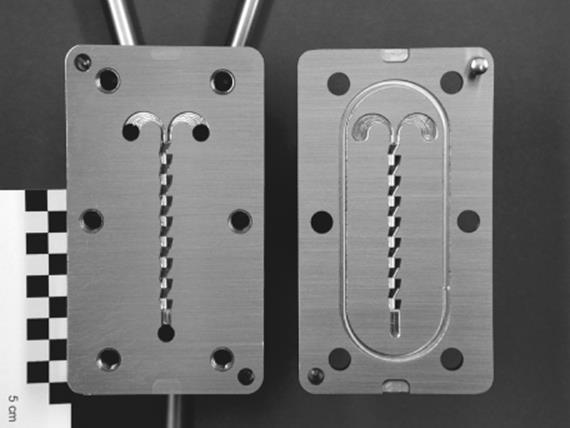
In one mini-packed bed reactor, standard porous catalyst particles were inserted in a mini-flow-through chamber (Figure 9.22) [65, 68, 69]. Filling of the catalyst slurry is achieved via inlet channels, being at both sides at the beginning of the packed bed. An inlet manifold feeds alternately gas and liquid streams into this reaction chamber thereby achieving a high degree of dispersion. An array of microstructured columns acts as filter at the outlet and retains the catalyst particles.
Figure 9.22 A mini-packed bed reactor. Source: By courtesy of the American Chemical Society [68].
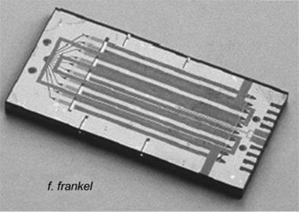
A multichannel packed bed reactor was also produced (Figure 9.23) [68, 69]. The gas flow is distributed by star-type manifolds to the 10 reaction units. However, to achieve commercial production, a complex arborescence structure is required, taking into account two phase flow distribution and a multitude of manifolds for gas and liquid inlets. Each packed bed channel is subject to a large pressure drop. Large pressure drop indicates high energy requirements and higher costs [95].
Figure 9.23 Image of a numbered up 10-channel mini-packed bed reactor microreactor. Source: By courtesy of IEEE) [69].
A cartridge heater is inserted in the cover plate of the packed bed reactor [68]. The base plate provides conduits to the microreactor. The outlets are standard high-pressure fittings. Thermocouples are inserted in the slurry feed channels.
Microfabrication uses photolithography and etching [68, 69]. A time-multiplexed inductively coupled plasma etch process was used for making the microchannels. The microstructured plate is covered with a Pyrex wafer by anodic bonding.
A flow-pattern map comprises dispersed flow, annular flow, slug-dispersed flow, and slug-annular flow [69]. The highest specific interface measured amounts to 16 000 m2/m3. A porous surface structure (100 cm2) in the reaction channel can be generated by a sulfurhexafluoride plasma etch process with silicon nitride masking [69].
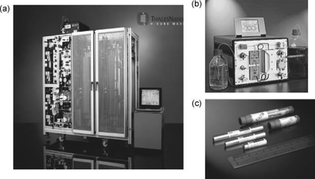
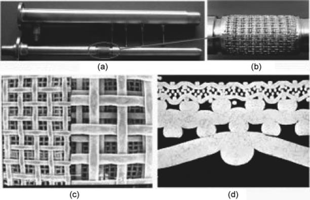
Another concept of packed bed microreactor systems are the Thales Nano continuous-flow reactors [96]. They are meant for hydrogenation (H-cube) and ozonolysis (O-cube) reactions. The catalyst is packed inside the reactor in a form of disposable cartridge (CatCart) (Figure 9.24). During a reaction, a mixture of gas and dissolved substrate enters the CatCart and adsorbs onto the catalyst bed. The reaction takes place on the catalyst, while the gas/liquid mixture passes through the cartridge. The product then flows out of the CatCart and goes to a collection vial. After thorough washing with solvent, the CatCart may be used again with another different substrate. This process can be repeated until the catalyst deactivates.
Figure 9.24 Thales nano reactors assembled: (a) H-Cube Maxi reactor. (b) H–Cube Midi. (c) CatCart catalyst.
9.2.2.4 Membrane Microreactors
Following the principles of process intensification, there has been recently a growing interest in integration of unit operations by merging a microreactor with a membrane separation unit. The concept of membrane microreactors is applied in biocatalysis [97, 98], and chemical catalysis where various catalysts can be attached to the membrane pores (zeolites [99], carbon nanofibers as support [100], metals [101]) (Figure 9.25).
Figure 9.25 (a) Modified surface obtained by functionalized microstructure fabricated from layer-by-layer nanozeolite-assembled network. (b) Membrane of cross-linking enzyme aggregate formed at microchannel surface. Source: Adopted from Ref. [98].
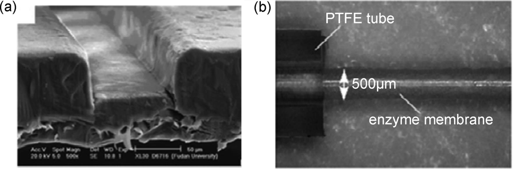
Nylon, PTFE, or ceramic membranes formed within a microchannel can be used also as a catalyst support [98]. The most of the demonstrated reactions involved two liquid phases and separated aqueous from an organic phase.
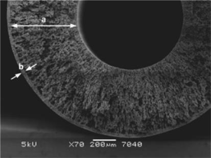
Besides, gas–liquid reactions can be performed within a membrane microreactor where membrane serves for product separation and thereby limits product inhibition [100]. In this version, the fabrication and operation of new hybrid membrane microreactors for gas–liquid–solid reactions is described. The reactors consist of porous stainless steel tubes onto which carbon nanofibers (CNFs) are grown as catalyst support (Figure 9.26). CNFs have high surface area, so they can be efficiently used as a catalyst support.
Figure 9.26 Cross-section of the porous stainless steel hollow fiber after the sintering step: (a) wall of the hollow fiber with thin macro voids and (b) outer skin of the hollow fiber with a denser structure [100]. Source: By courtesy of Elsevier.
Nitrite reduction in water is tested as a model reaction. It is shown that nitrite reduction proceeds by both catalytic reduction (with Pd and H2) and by the reactor material itself (i.e., by Fe on CNFs). Eventually, the latter effect will exhaust in time and the reaction will still proceed with the immobilized Pd-catalyst on the CNFs and the membrane-assisted supply of hydrogen. Results proved that the porous metallic membrane microreactors with carbon nanofibers are suitable materials for the reduction of nitrite and the reactor design is very promising for the multiphase microreactor technologies [100].
9.2.2.5 Tube in Tube Microreactor
A high-throughput tube-in-tube microchannel reactor was recently designed and developed as a novel gas–liquid contactor [102, 103].
Two groups described a tube-in-tube gas–liquid microreactor – a microporous tube-in-tube microchannel reactor [102] (Figure 9.27) and a reactor/saturation module based on a gas-permeable Teflon AF-2400 membrane [103].
Figure 9.27 Microporous tube-in-tube microreactor. (a) The photo of MTMCR, (b) microporous section; SEM images of the front (c) and cross (d) sections of sintering metal wire mesh [102]. Source: By courtesy of Elsevier.
Both heterogeneous and homogeneous catalytic hydrogenation reactions were efficiently carried out at elevated pressure in flow. Rapid diffusion of pressurized gas occurs through gas-permeable tubing to quickly create a gas saturated solvent stream in <10 s [103]. Liquid (usually organic solvent) is passed through a gas-permeable inner tube, which is nested inside a closed, thick-walled outer tube filled under pressure with a reactive gas. The gas is able to diffuse across the membrane into the liquid phase, but the liquid cannot move in the opposite direction. Further, the introduction of other gases such as CO, CO2, ethene, and ethyne under flow-through conditions is possible [103]. The module can be used as a reactor itself as well as for providing a solvent feed stream presaturated with gas.
An increase of the gas or liquid flow rate (over 60 times higher than that of a T-type microchannel) is observed [102]. In combination with a reduction of the micropore size and small channel width, the gas–liquid mass transfer in a microporous tube-in-tube microchannel reactor is greatly intensified.
9.2.3 Scaling Up of Microreactor Devices
The concept of scaling up of microreactor devices is widely researched. Scaling up in the form of numbering up (parallelization) or internal scaling out is evaluated. As opposed to traditional reactors, microchannel reactors keep the same reactor scale and achieve high throughput when upscaled. Most scaling up approaches refer to a single phase or two-phase liquid–liquid system [68, 104, 105]. The challenge when scaling up a gas–liquid system is to achieve equal flow distribution. Multiphase flow distribution in microchannels is most often realized via external distribution [68, 106]. Design criteria for a barrier-based gas–liquid external flow distributor for parallel microchannels are presented in Ref. [70] (Figure 9.28).
Figure 9.28 Schematic representation of barrier-based gas–liquid flow distributor for four parallel microchannels. (G: gas, L: liquid, M: manifold, B: barrier channel, T: T-mixer) [70]. Source: By courtesy of Elsevier.
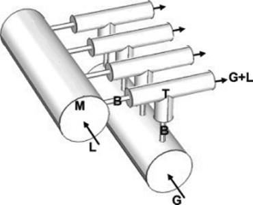
The optimal distributor design, which would prevent gas–liquid channeling, minimize nonuniformity of the gas and liquid flows, and have a minimum hydraulic resistance, is obtained via an experimental parametric approach. Five design parameters are evaluated and the following design criteria are established:
· Gas–liquid channeling is prevented when the gas and liquid manifolds have equal pressures.
· The lower and upper limits of hydraulic resistances in the barrier channels are 4 ≤ ΔPB ≤ 25.
· The optimal operational window is realized when the gas to liquid flow ratio is kept constant and the ratio of the maximum over minimum flow rates remains <20.
· The manufacturing tolerance of the barrier channels has the highest impact on the flow nonuniformity. The flow nonuniformity is proportional to four times the variation in the inner diameter of the barrier channels.
· The required hydraulic resistance in the barrier channels reduces by lowering the variation in the inner diameters of the T-mixers and microchannels.
Several companies have participated in upscaling and commercializing major gas–liquid contacting microdevices. Among them Velocys, DSM, Thalesnano, Am Technology, and Syrris own a wide range of high-throughput gas–liquid devices.