Process Technology: An Introduction - Haan A.B. 2015
12 Membrane separations
12.4 Solubility driven processes
12.4.1 Gas and vapor permeation
In gas permeation, certain components of the feed permeate a permselective membrane at a much higher rate than the others. The driving force is the pressure difference between the pressurized feed gas and the lower pressure permeate. This pressure difference can be established either by applying a high pressure on the feed side and/or maintaining a low pressure on the permeate side. Although porous membranes are also applicable, all current commercial gas separations are based on diffusion through dense polymer films. As was shown earlier, the ability of a membrane to separate two gases, called the ideal membrane separation factor SF*, is the ratio of their permeabilities:
![]()
(12.12)
The ratio of the diffusion coefficients represents the mobility selectivity, reflecting the different sizes of two molecules. In polymeric materials the diffusion coefficient decreases with increasing molecular size. Hence, the mobility selectivity always favors the passage of small molecules over large ones. The ratio of the sorption coefficients can be viewed as the solubility selectivity, reflecting the relative condensabilities of the two gases. If molecule 1 is larger than 2, the mobility selectivity will always be less than one, while the sorption selectivity will normally be greater than one. The balance between the sorption selectivity and the mobility selectivity determines whether a membrane material is selective for large or small molecules in a gas mixture.
Both hollow-fiber and spiral-wound modules are used in gas separation applications. Spiral-wound modules are favored if the gas stream contains entrained droplets, as in air or natural gas separations. The first large-scale commercial application was the recovery of hydrogen from ammonia purge gas streams. Hydrogen is a small, noncondensable gas, which is highly permeable compared to all other gases. A typical membrane system flow scheme is shown in Fig. 12.18. A two-step membrane design is used to reduce the cost of recompressing the hydrogen permeate stream to the very high pressures of ammonia reactors. Today the largest gas separation process in use is the production of nitrogen from air. The first membranes were based on polysulfone and ethylcellulose with oxygen-nitrogen selectivities of 4-5. With the second generation materials selectivities in the range 7-8 and higher fluxes are obtained, making the economics of small-scale nitrogen production very favorable. A growing application is the removal of condensable organic vapors from air and other streams. These processes fall into three main categories and use rubbery membranes that are more permeable to the organic vapor. The first category concerns small systems to recover chlorinated, fluorinated, and other high value hydrocarbons from process vent streams. The driving force for their installation is primarily economic. The second category is larger units to recover hydrocarbon vapors from petroleum transfer operations. Although these hydrocarbons have some economic value, the main driving force is environmental. The third category is the recovery and recycling of monomers in polymerization plants. Vent streams of these plants contain large amounts of monomer that can be removed by organic-vapor-permeable membranes and returned to the reactor. Fig. 12.19 shows an example for the recovery of propylene from the nitrogen used for devolatilization in a polypropylene plant. Both the clean nitrogen and the propylene are recycled within the polypropylene plant.
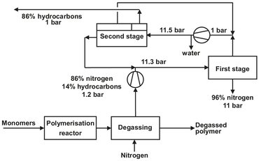
Fig. 12.19: Two stage membrane unit for propylene and nitrogen recovery in a polypropylene plant.
12.4.2 Pervaporation
In this separation process a multicomponent liquid stream is passed across a membrane that preferentially permeates one or more of the components. As the feed liquid flows across the membrane surface, the permeated components pass through the membrane as a vapor. Transport is induced by maintaining a vapor pressure on the permeate side of the membrane lower than the vapor pressure of the feed liquid. As illustrated by Fig. 12.20, the pressure difference is maintained by condensing the permeate vapor, which is removed as a concentrated permeate fraction.
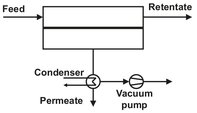
Fig. 12.20: Schematic of a pervaporation process with a downstream vacuum.
Pervaporation is a complex process in which both mass and heat transfer occurs. The separation principle in pervaporation is based on differences in solubility and diffusivity. The most convenient method to describe the separation principles of pervaporation is to divide the overall process into two steps. The first is an (imaginary) evaporation of the feed liquid to form a saturated vapor phase on the feed side of the membrane. The second is permeation of this vapor through the membrane to the low pressure permeate side of the membrane. The evaporation step produces a separation according to the partial vapor pressures of the components in equilibrium with the feed solution. The permeation of components through the membrane is largely analogous to conventional gas permeation. Separation is achieved by the combination of solubility and diffusivity in the dense membrane layer. The total separation factor is now proportional to the product of these two contributions:
![]()
(12.13)
To achieve good separations, both terms should be large. Although one might conclude that pervaporation is most suited to the removal of volatile components from relatively involatile components, membranes can be made sufficiently selective to make nonvolatile components preferentially permeate the membrane.
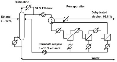
Fig. 12.21: Schematic of integrated distillation/pervaporation plant for ethanol dehydration.
The three major applications of pervaporation are solvent dehydration, recovery organics from water, and the separation of mixed organic solvents. Most developed is the separation of water from concentrated alcohol solutions such as ethanol and isopropanol. A flow scheme for an integrated distillation-pervaporation plant is shown in Fig. 12.21. The distillation column produces a concentrated ethanol stream, which is fed to the pervaporation system to break the azeotrope and obtain nearly pure ethanol. A second interesting application of dehydration membranes is the shift of chemical equilibrium in esterification reactions:
![]()
(12.14)
In these reactions the degree of conversion is limited by water buildup in the reactor. Continuous removal of water forces the equilibrium to the right, and almost complete conversion can be achieved. The second application is the separation of small amounts of organic solvents from contaminated water. This separation is relatively easy, because organic compounds and water exhibit distinct membrane permeation properties. Pervaporation for the separation of organic/organic mixtures is currently under development and could become a major application in the near future.