What Is Mathematics? An Elementary Approach to Ideas and Methods, 2nd Edition (1996)
CHAPTER III. GEOMETRICAL CONSTRUCTIONS. THE ALGEBRA OF NUMBER FIELDS
PART II. VARIOUS METHODS FOR PERFORMING CONSTRUCTIONS
§5. CONSTRUCTIONS WITH OTHER TOOLS. MASCHERONI CONSTRUCTIONS WITH COMPASS ALONE
*1. A Classical Construction for Doubling the Cube
Until now we have considered only problems of geometrical construction that use the straightedge and compass alone. When other instruments are allowed the variety of possible constructions naturally becomes more extensive. For example, the Greeks solved the problem of doubling the cube in the following way. Consider (as in Fig. 46) a rigid right angle MZN and a movable right-angled cross B, VW, PQ. Two additional edges RS and TU are allowed to slide perpendicularly to the arms of the right angle. On the cross let two fixed points E and G be chosen such that GB = aand BE = f have prescribed lengths. By placing the cross so that the points E and G lie on NZ and MZ respectively, and sliding the edges TU and RS, we can bring the entire apparatus into a position where we have a rectangle ADEZ through whose vertices A, D, E pass the arms BW, BQ, BVof the cross. Such an arrangement is always possible if f > a. We see at once that a:x = x:y = y:f, whence, if f is set equal to 2a in the apparatus, x3 = 2a3. Hence x will be the edge of a cube whose volume is double that of the cube with edge a. This is what is required for doubling the cube.
2. Restriction to the Use of the Compass Alone
While it is only natural that by permitting a greater variety of instruments we can solve a large collection of construction problems, one might expect that more restrictions on the tools allowed would narrow the class of possible constructions. Hence it was a very surprising discovery, made by the Italian Mascheroni (1750–1800), that all geometrical constructions possible by straightedge and compass can be made by the compass alone. Of course, one cannot draw the straight line joining two points without a straightedge, so that this fundamental construction is not really covered by the Mascheroni theory. Instead, one must think of a straight line as given by any two points on it. By using the compass alone, one can find the point of intersection of two lines given in this way, and likewise the intersections of a given circle with a straight line.
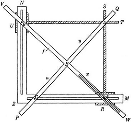
Fig. 46. An instrument for doubling the cube.
Perhaps the simplest example of a Mascheroni construction is the doubling of a given segment AB. The solution was given on page 144. On page 145 we bisected a straight segment. Now we shall solve the problem of bisecting a given arc AB of a circle with given center O. Theconstruction is as follows: from A and B as centers, swing two arcs with radius AO. From O lay off arcs OP and OQ equal to AB. Then swing two arcs with PB and QA as radii and with P and Q as centers, intersecting at R. Finally, with OR as radius, describe an arc with either P or Q as center until it intersects AB; this point of intersection is the required midpoint of the arc AB. The proof is left as an exercise for the reader.
It would be impossible to prove Mascheroni’s general theorem by actually giving a construction by compass alone for every construction possible with ruler and compass, since the number of possible constructions is not finite. But we may arrive at the same goal by proving that each of the following four fundamental constructions is possible with compass alone:
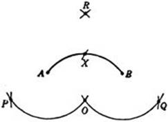
Fig. 47. Bisecting an are with the compass.
1. To draw a circle with given center and radius.
2. To find the points of intersection of two circles.
3. To find the points of intersection of a straight line and a circle.
4. To find the points of intersection of two straight lines.
Any geometrical construction in the usual sense, ruler and compass permitted, consists of a finite succession of these elementary constructions. The first two of these are clearly possible with the compass alone. The solutions of the more difficult problems 3 and 4 depend on the properties of inversion developed in the preceding section.
Let us solve problem 3, that of finding the points of intersection of a circle C and a straight line given by the two points A and B. With centers A and B and radii AO and BO, respectively, draw two arcs, intersecting again at P. Now determine the point Q inverse to P with respect to C, by the construction with compass alone given on p. 144. Draw the circle with center Q and radius QO (this circle must intersect C); the points of intersection X and X’ of this circle with the given circle C are the required points. To prove this we need only show that X and X′ are equidistant fromO and P, since A and B are so by construction. This follows from the fact that the inverse of Q is a point whose distance from X and X′ is equal to the radius of C (p. 144). Note that the circle through X, X′, and O is the inverse of the line AB, since this circle and the line AB intersect C at the same points. (Points on the circumference of a circle are their own inverses.)
The construction is invalid only if the line AB goes through the center of C. But then the points of intersection can be found, by the construction given on page 148, as the midpoints of arcs on C obtained by swinging around B an arbitrary circle which intersects C in B1 and B2.
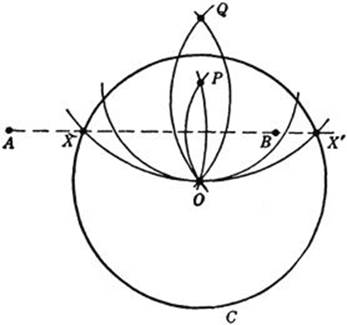
Fig. 48. Intersection of circle and line not through center.
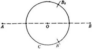
Fig. 49. Intersection of circle and line through center.
The method of determining the circle inverse to the line joining two given points permits an immediate solution of problem 4. Let the lines be given by AB and A′B′ (Fig. 50). Draw any circle C in the plane, and by the preceding method find the circles inverse to AB and A′B′. These circles intersect at O and at a point Y. The point X inverse to Y is the required point of intersection, and can be constructed by the process already used. That X is the required point is evident from the fact that Y is the only point that is inverse to a point of both AB and A′B′; hence the point X inverse to Y must lie on both AB and A′B′.
With these two constructions we have completed the proof of the equivalence between Mascheroni constructions using only the compass and the conventional geometrical constructions with ruler and compass. We have taken no pains to provide elegant solutions for individual problems, since our aim was rather to give some insight into the general scope of the Mascheroni constructions. We shall, however, give as an example the construction of the regular pentagon. More precisely, we shall find five points on a circle which will be the vertices of a regular inscribed pentagon.
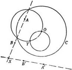
Fig. 50. Intersection of two lines.
Let A be any point on the given circle K. The side of a regular inscribed hexagon is equal to the radius of K. Hence we can find points B, C, D on K such that ![]() (Fig. 51). With A and D as centers and A C as radius we draw arcs meeting at X. Then if O is the center of K, an arc about A of radius OX will meet K at the midpoint F of
(Fig. 51). With A and D as centers and A C as radius we draw arcs meeting at X. Then if O is the center of K, an arc about A of radius OX will meet K at the midpoint F of ![]() (see p. 148). Now with the radius of K we draw arcs about F meeting K at G and H. Let Y be a point whose distance from G and H is OX, and which is separated from X by O. Then A Y will be equal to a side of the required pentagon. The proof is left as an exercise for the reader. Note that only three different radii were used in the construction.
(see p. 148). Now with the radius of K we draw arcs about F meeting K at G and H. Let Y be a point whose distance from G and H is OX, and which is separated from X by O. Then A Y will be equal to a side of the required pentagon. The proof is left as an exercise for the reader. Note that only three different radii were used in the construction.
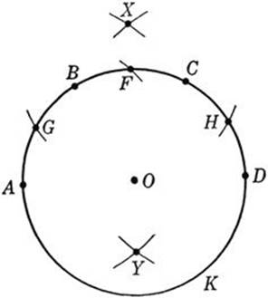
Fig. 51. Construction of the regular pentagon.
In 1928 the Danish mathematician Hjelmslev found in a Copenhagen bookstore a copy of a book, Euclides Danicus, published in 1672 by an obscure author G. Mohr. From the title one might infer that this work was simply a version of, or a commentary on Euclid’s Elements. But when Hjelmslev examined the book, he found to his surprise that it contained essentially the Mascheroni problem and its complete solution, found long before Mascheroni.
Exercises: The following is a description of Mohr’s constructions. Check their validity. Why do they solve the Mascheroni problem?
1) On a segment AB of length p erect a perpendicular segment BC. (Hint: Extend AB by a point D such that AB = BD. Draw arbitrary circles around A and D and thus determine C.)
2) Two segments of length p and q with p > q are given somewhere in the plane. Find a segment of the length ![]() by making use of 1).
by making use of 1).
3) From a given segment a construct the segment a![]() . (Hint: Observe that
. (Hint: Observe that ![]()
4) With given segments p and q find a segment ![]() . (Hint: Use the relation x2 = 2p2 − (p2 − q2). Find other similar constructions.
. (Hint: Use the relation x2 = 2p2 − (p2 − q2). Find other similar constructions.
5) Using the previous results, find segments of length p + q and p − q if segments of length p and q are given somewhere in the plane.
6) Check and prove the following construction for the midpoint M of a given segment AB of length a. On the extension of AB find C and D such that CA = AB = BD. Construct the isosceles triangle ECD with EC = ED = 2a, and find M as the intersection of the circles with diameters ECand ED.
7) Find the orthogonal projection of a point A on a line BC.
8) Find x such that x:a = p:q, if a, p, and q are given segments.
9) Find x = ab, if a and b are given segments.
Inspired by Mascheroni, Jacob Steiner (1796–1863) tried to single out as a tool the straightedge instead of the compass. Of course, the straightedge alone does not lead out of a given number field, and hence cannot suffice for all geometrical constructions in the classical sense. It is all the more remarkable that Steiner was able to restrict the use of the compass to a single application. He proved that all constructions in the plane which are possible with straightedge and compass are possible with the straightedge alone, provided that a single fixed circle and its center are given. These constructions require projective methods and will be indicated later (see page 197).
* This circle and its center cannot be dispensed with. For example, if a circle, but not its center, is given,’ it is impossible to construct the latter by the use of the straightedge alone. To prove this we shall make use of a fact that will be discussed later (p. 220): There exists a transformation of the plane into itself which has the following properties: (a) the given circle is fixed under the transformation. (b) Any straight line is carried into a straight line. (c) The center of the circle is carried into some other point. The mere existence of such a transformation shows the impossibility of constructing with the straightedge alone the center of the given circle. For, whatever the construction might be, it would consist in drawing a certain number of straight lines and finding their intersections with one another and with the given circle. Now if the whole figure, consisting of the given circle together with all points and lines of the construction, is subjected to the transformation whose existence we have assumed, the transformed figure will satisfy all the requirements of the construction, but will yield as result a point other than the center of the given circle. Hence such a construction is impossible.
3. Drawing with Mechanical Instruments. Mechanical Curves. Cycloids
By devising mechanisms to draw curves other than the circle and the straight line we may greatly enlarge the domain of constructible figures. For example, if we have an instrument for drawing the hyperbolas xy = k, and another for drawing parabolas y = ax2 + bx + c, then any problem leading to a cubic equation,
(1) ax3 + bx2 + cx = k,
may be solved by construction, using only these instruments. For if we set
(2) xy = k, y = ax2 + bx + c,
then solving equation (1) amounts to solving the simultaneous equations (2) by eliminating y; i.e. the roots of (1) are the x-coordinates of the points of intersection of the hyperbola and parabola in (2). Thus the solutions of (1) can be constructed if we have instruments with which to draw the hyperbola and parabola of equations (2).
Since antiquity mathematicians have known that many interesting curves can be defined and drawn by simple mechanical instruments. Of these “mechanical curves” the cycloids are among the most remarkable. Ptolemy (circa 200 A.D.) used them in a very ingenious way to describe the movements of the planets in the heavens.

Fig. 52. Graphical solution of a cubic equation.
The simplest cycloid is the curve described by a fixed point on the circumference of a circle which rolls without slipping along a straight line. Figure 53 shows four positions of the point P on the rolling circle. The general appearance of the cycloid is that of a series of arches resting on the line.
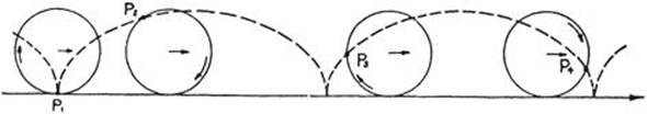
Fig. 53. The cycloid.
Variations of this curve may be obtained by choosing the point P either inside the circle (as on a spoke of a wheel) or on an extension of its radius (as on the flange of a train wheel). Figure 54 illustrates these two curves.
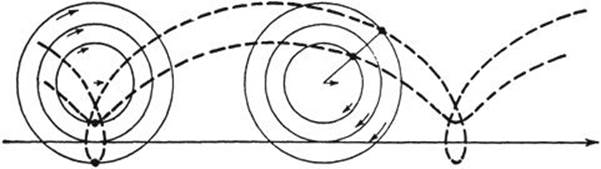
Fig. 54. General cycloids.
A further variation of the cycloid is obtained by allowing a circle to roll, not along a straight line, but on another circle. If the rolling circle c of radius r remains internally tangent to the larger circle C of radius R, the locus generated by a point fixed on the circumference of c is called ahypocycloid.
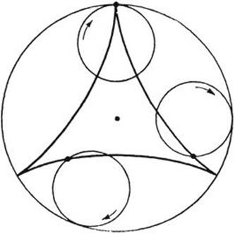
Fig. 55. Three-cusped hypocycloid.
If the circle c describes the whole circumference of C just once, the point P will return to its original position only if the radius of C is an integral multiple of that of c. Figure 55 shows the case where R = 3r. More generally, if the radius of C is m/n times that of c, the hypocycloid will close up after n circuits around C, and will consist of m arches. An interesting special case occurs if R= 2r. Any point P of the inner circle will then describe a diameter of the larger circle (Fig. 56). We propose the proof of this fact as a problem for the reader.
Still another type of cycloid can be generated by means of a rolling circle remaining externally tangent to a fixed circle. Such a curve is called an epicycloid.
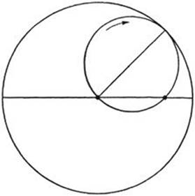
Fig. 56. Straight motion by points on a circle rolling in a circle of double radius.
*4. Linkages. Peaucellier’s and Hart’s Inversors
We leave for the present the subject of cycloids (they will appear again in an unexpected place) to consider other methods of generating curves. The simplest mechanical instruments for tracing curves are the linkages. A linkage consists of a set of rigid rods, connected in some manner at movable joints, in such a way that the whole system has just enough freedom to allow a point on it to describe a certain curve. The compass is really a simple linkage, consisting in principle of a single rod which is fastened at one point.
Linkages have long been used in machine construction. One of the historically famous examples, the “Watt parallelogram,” was invented by James Watt to solve the problem of linking the piston of his steam engine to a point on the flywheel in such a way that the rotation of the flywheel would move the piston along a straight line. Watt’s solution was only approximate, and despite the efforts of many distinguished mathematicians, the problem of constructing a linkage to move a point precisely on a straight line remained unsolved. At one time, when proofs for the impossibility of solutions to certain problems were attracting wide attention, the conjecture was made that the construction of such a linkage was impossible. It was a great surprise when, in 1864, a French naval officer. Peaucellier, invented a simple linkage that solved the problem. With the introduction of efficient lubricants the technical problem for steam engines had by then lost its significance.
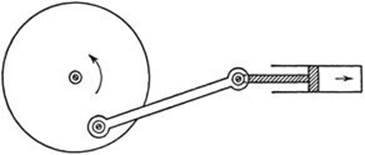
Fig. 57. Rectilinear motion transformed into rotation.
The purpose of Peaucellier’s linkage is to convert circular into rectilinear motion. It is based on the theory of inversion discussed in §4. As shown in Figure 58, the linkage consists of seven rigid rods; two of length t, four of length s, and a seventh of arbitrary length. O and R are two fixed points, placed so that OR = PR. The entire apparatus is free to move, subject to the given conditions. We shall prove that, as P describes an arc about R with radius PR, Q describes a segment of a straight line. Denoting the foot of the perpendicular from S to OQ by T, we observe that
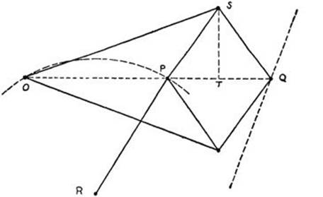
Fig. 58. Peaucellier’s transformation of rotation into true rectilinear motion.
OP·OQ = (OT – PT)(OT + PT) = OT2 – PT2
= (OT2 + ST2) – (PT2 + ST2)
= t2 – s2.
The quantity t2 – s2 is a constant which we call r2. Since OP·OQ = r2, P and Q are inverse points with respect to a circle with radius r and center O. As P describes its circular path (which passes through O), Q describes the curve inverse to the circle. This curve must be a straight line, for we have proved that the inverse of a circle passing through O is a straight line. Thus the path of Q is a straight line, drawn without using a straightedge.
Another linkage that solves the same problem is Hart’s inversor. This consists of five rods connected as in Figure 59. Here AB = CD,
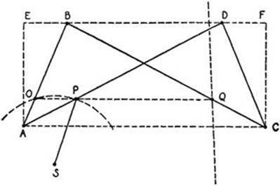
Fig. 59. Hart’s inversor.
BC = AD. O, P and Q are points fixed on the rods AB, AD, CB, respectively, such that AO/OB = AP/PD = CQ/QB = m/n. Points O and S are fixed in the plane so that OS = PS, while the rest of the linkage is free to move. Evidently, AC is always parallel to BD. Hence, O, P and Q are collinear, and OP is parallel to AC. Draw AE and CF perpendicular to BD. We have
AC·BD = EF·BD = (ED + EB) (ED – EB) = ED2 – EB2. But ED2 + AE2 = AD2, and EB2 + AE2 = AB2. Hence ED2 – EB2 = AD2 – AB2. Now
OP/BD = AO/AB = m/(m + n) and OQ/AC = OB/AB = n/(m + n). Thus
OP·OQ = [mn/(m + n)2]BD·AC = [mn/(m + n)2](AD2 – AB2).
This quantity is the same for all possible positions of the linkage. Therefore P and Q are inverse points with respect to some circle about O. When the linkage is moved, P describes a circle about S which passes through O, while its inverse Q describes a straight line.
Other linkages can be constructed (at least in principle) which will draw ellipses, hyperbolas, and indeed any curve given by an algebraic equation f(x, y)= 0 of any degree.