AP Physics C Exam
Part IV
Content Review for the AP Physics C Exam
Chapter 8
Rotational Motion
INTRODUCTION
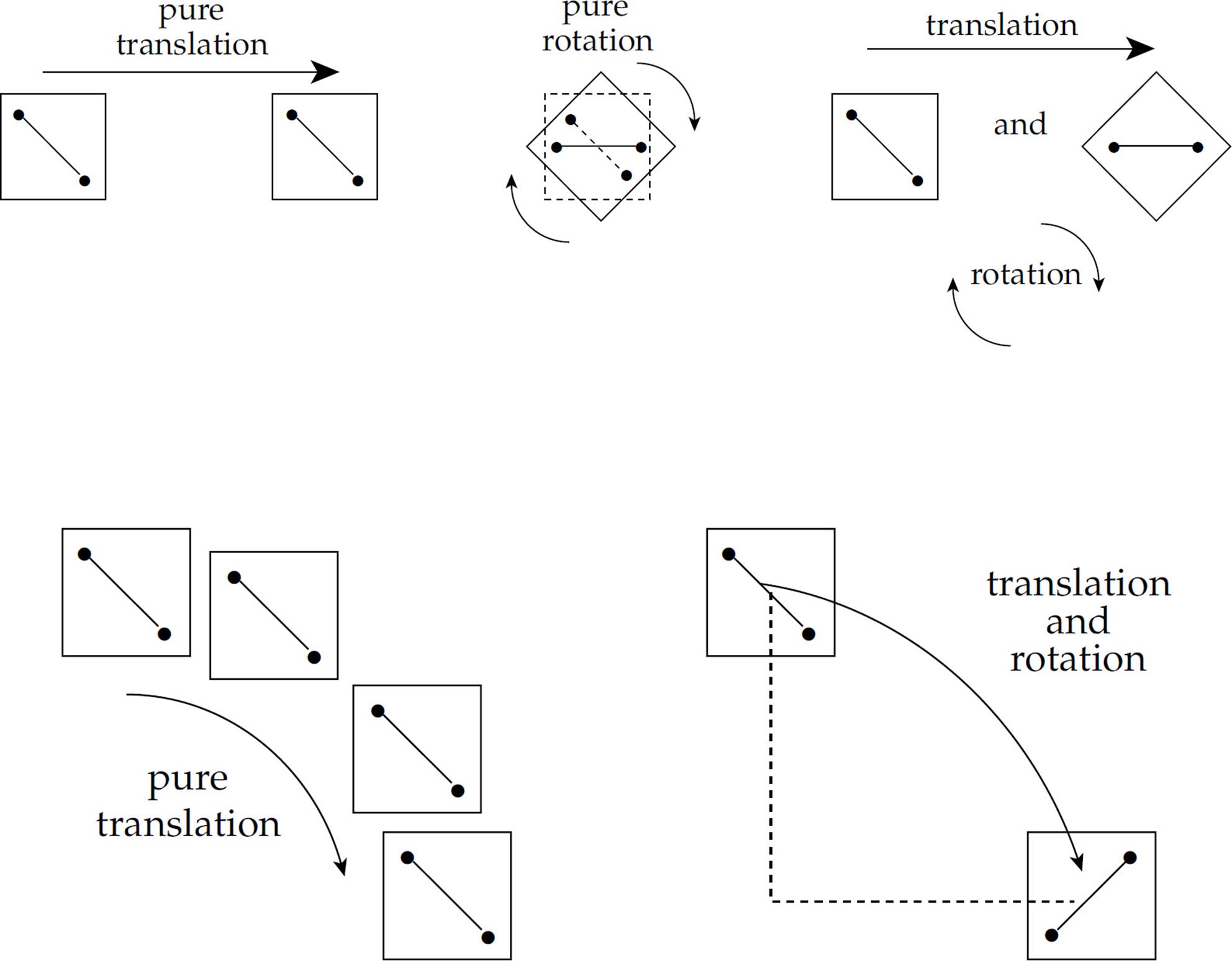
So far we’ve studied only translational motion: objects sliding, falling, or rising, but in none of our examples have we considered spinning objects. We will now look at rotation, which will complete our study of motion. All motion is some combination of translation and rotation, which are illustrated in the figures below. Consider any two points in the object under study (on the left) and imagine connecting them by a straight line. If this line does not turn while the object moves, then the object is translating only. However, if this line does not always remain parallel to itself while the object moves, then the object is rotating.
ROTATIONAL KINEMATICS
Mark several dots along a radius on a disk, and call this radius the reference line. If the disk rotates about its center, we can use the movement of these dots to talk about angular displacement, angular velocity, and angular acceleration.
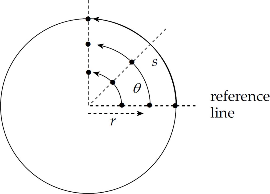
If the disk rotates as a rigid body, then all three dots shown have the same angular displacement,  θ. In fact, this is the definition of a rigid body: All points along a radial line always have the same angular displacement.
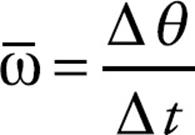
Just as the time rate-of-change of displacement gives velocity, the time rate-of-change of angular displacement gives angular velocity, denoted by ω (omega). The definition of the average angular velocity is:
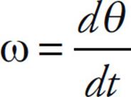
Note that if we let the time interval t approach 0, then the equation above leads to the definition of the instantaneous angular velocity:
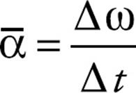
And, finally, just as the time rate-of-change of velocity gives acceleration, the time rate-of-change of angular velocity gives angular acceleration, or α (alpha). The definition of the average angular acceleration is:
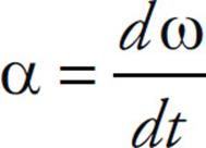
If we let the time interval  t approach 0, then the equation above leads to the definition of the instantaneous angular velocity:
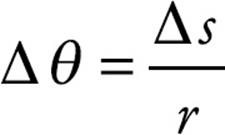
On the rotating disk illustrated on the previous page, we said that all points undergo the same angular displacement in any given time interval; this means that all points on the disk have the same angular velocity, ω, but not all points have the same linear velocity, v. This follows from the definition of radian measure. Expressed in radians, the angular displacement, θ, is related to the arc length,  s, by the equation
Rearranging this equation and dividing by t, we find that
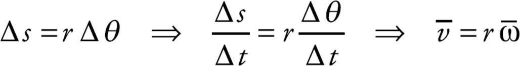
Or, using the equations v = ds/dt and ω = dθ/dt,
![]()
Therefore, the greater the value of r, the greater the value of v. Points on the rotating body farther from the rotation axis move more quickly than those closer to the rotation axis.
From the equation v = rω, we can derive the relationship that connects angular acceleration and linear acceleration. Differentiating both sides with respect to t (holding r constant), gives us
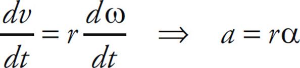
(It’s important to realize that the acceleration a in this equation is not centripetal acceleration; it’s tangential acceleration, which arises from a change in speed caused by an angular acceleration. By contrast, centripetal acceleration does not produce a change in speed.) Often, tangential acceleration is written as at to distinguish it from centripetal acceleration (ac).
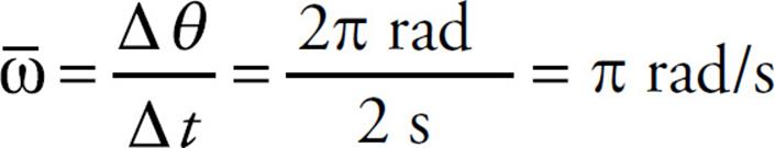
Example 1 A rotating, rigid body makes one complete revolution in 2 s. What is its average angular velocity?
Solution. One complete revolution is equal to an angular displacement of 2π radians, so the body’s average angular velocity is
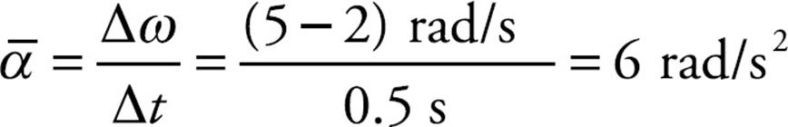
Example 2 The angular velocity of a rotating disk increases from 2 rad/s to 5 rad/s in 0.5 s. What’s the disk’s average angular acceleration?
Solution. By definition,
Example 3 A disk of radius 20 cm rotates at a constant angular velocity of 6 rad/s. How fast does a point on the rim of this disk travel (in m/s)?
Solution. The linear speed, v, is related to the angular speed, ω, by the equation v = rω. Therefore,
v = rω = (0.20 m)(6 rad/s) = 1.2 m/s
Note that although we typically write the abbreviation rad when writing angular measurements, the radian is actually a dimensionless quantity, since, by definition, θ = s/r. So θ = 6 means the same thing as θ = 6 rad.
Example 4 The angular velocity of a rotating disk of radius 50 cm increases from 2 rad/s to 5 rad/s in 0.5 s. What is the linear tangential acceleration of a point on the rim of the disk during this time interval?
Solution. The linear acceleration a is related to the angular acceleration α by the equation a = rα. Since α = 6 rad/s2 (as calculated in Example 2), we find that
a = rα = (0.50 m)(6 rad/s2) = 3 m/s2
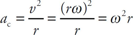
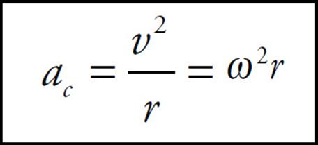
Example 5 Derive an expression for centripetal acceleration in terms of angular speed.
Solution. For an object revolving with linear speed v at a distance r from the center of rotation, the centripetal acceleration is given by the equation ac = v2/r. Using the fundamental equation v = rω, we find that
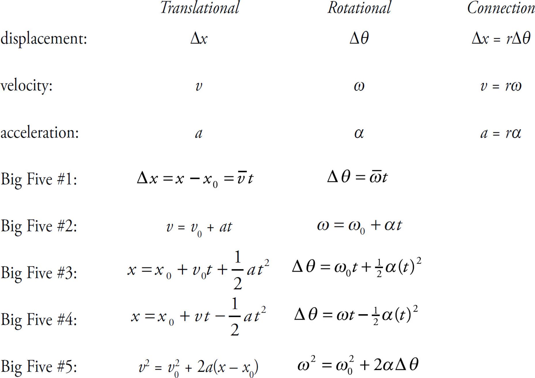
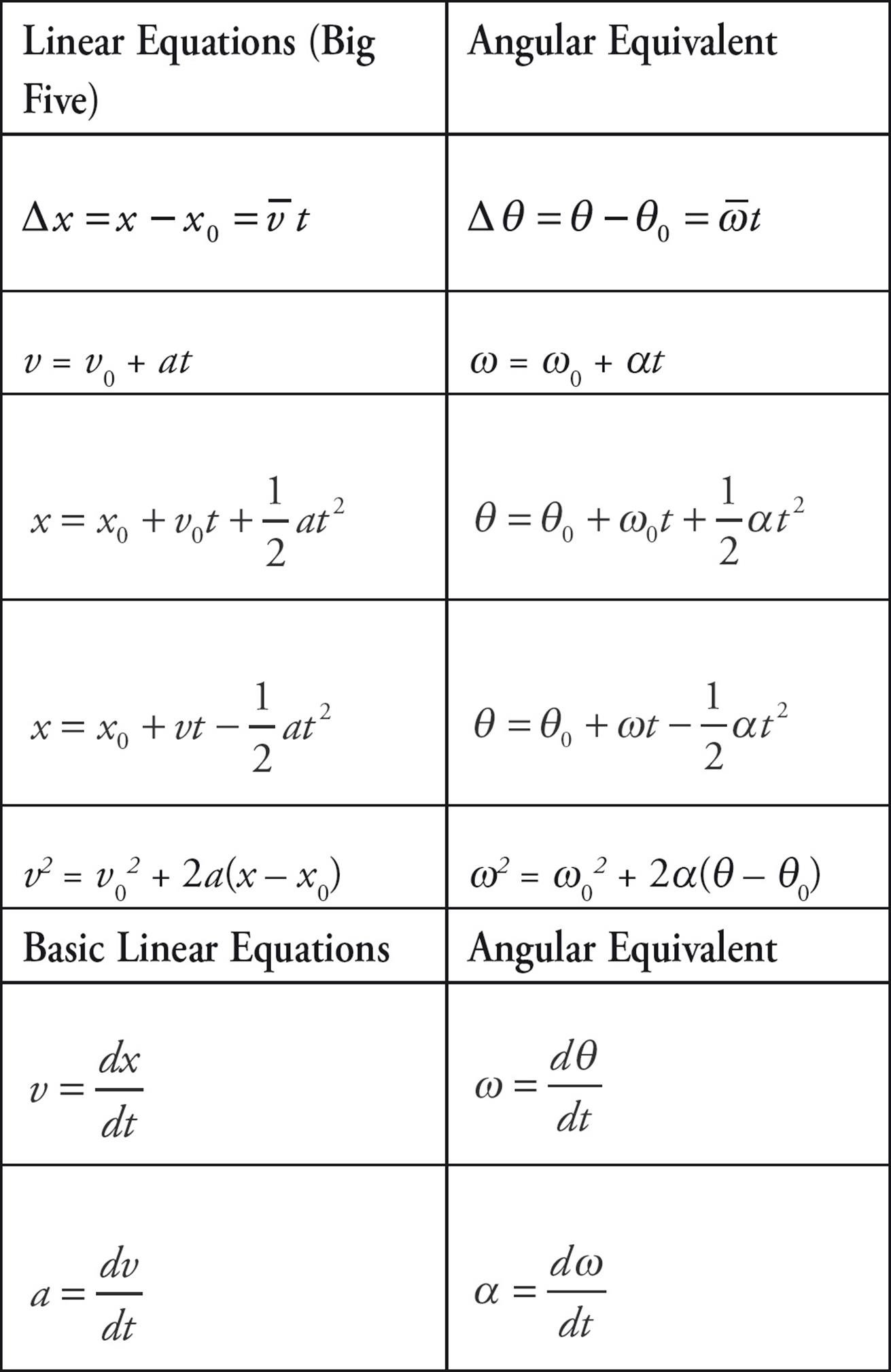
On the equation sheet for the free-response section, this information will be represented as follows:
THE BIG FIVE FOR ROTATIONAL MOTION
The simplest type of rotational motion to analyze is motion in which the angular acceleration is constant (possibly equal to zero). Another restriction that will make our analysis easier (and which doesn’t diminish the power and applicability of our results too much) is to consider rotational motion around a fixed axis of rotation. In this case, there are only two possible directions for motion. One direction, counterclockwise, is called positive (+), and the opposite direction, clockwise, is called negative (–).
Let’s review the quantities we’ve seen so far. The fundamental quantities for rotational motion are angular displacement (θ), angular velocity (ω), and angular acceleration (α). Because we’re dealing with angular acceleration, we know about changes in angular velocity, from initial velocity (ωi or ω0) to final velocity (ωf or simply ω—with no subscript). And, finally, the motion takes place during some elapsed time interval, t. Therefore, we have five kinematics quantities: θ, ω0, ω, α, and t.
These five quantities are interrelated by a group of five equations which we call the Big Five. They work in cases in which the angular acceleration is uniform. These equations are identical to the Big Five we studied in Chapter 4 but, in these cases, the translational variables (s, v, or a) are replaced by the corresponding rotational variables (θ, ω, or α, respectively).
In Big Five #1, because angular acceleration is constant, the average angular velocity is simply the average of the initial angular velocity and the final angular velocity: 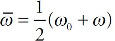 . Also, if we decide that ti = 0, then t = tf – ti = t – 0 = t, so we can just write “t” instead of “t” in the first four equations. This simplification in notation makes the equations a little easier to memorize.
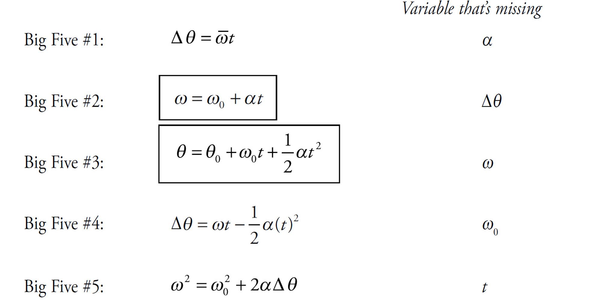
Each of the Big Five equations is missing exactly one of the five kinematics quantities and, as with the other Big Five you learned, the way you decide which equation to use is to determine which of the kinematics quantities is missing from the problem, and use the equation that’s also missing that quantity. For example, if the problem never mentions the final angular velocity—ω is neither given nor asked for—then the equation that will work is the one that’s missing ω; that’s Big Five #3.
Notice that Big Five #1 and #2 are simply the definitions of ![]() and
and ![]() written in forms that don’t involve fractions.
written in forms that don’t involve fractions.
Example 6 An object with an initial angular velocity of 1 rad/s rotates with constant angular acceleration. Three seconds later, its angular velocity is 5 rad/s. Calculate its angular displacement during this time interval.
Solution. We’re given ω0, t, and ω, and asked for θ. So α is missing, and we use Big Five #1:

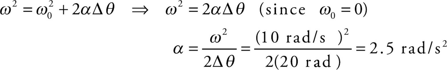
Example 7 Starting with zero initial angular velocity, a sphere begins to spin with constant angular acceleration about an axis through its center, achieving an angular velocity of 10 rad/s when its angular displacement is 20 rad. What is the value of the sphere’s angular acceleration?
Solution. We’re given ω0, θ, and ω, and asked for α. Since t is missing, we use Big Five #5:
To summarize, here’s a comparison of the fundamental quantities of translational and rotational motion and of the Big Five (assuming constant acceleration and a fixed axis of rotation):
ROTATIONAL DYNAMICS
The dynamics of translational motion involve describing the acceleration of an object in terms of its mass (inertia) and the forces that act on it; Fnet = ma. By analogy, the dynamics of rotational motion involve describing the angular (rotational) acceleration of an object in terms of itsrotational inertia and the torques that act on it.
TORQUE
Intuitively, torque describes the effectiveness of a force in producing rotational acceleration. Consider a uniform rod that pivots around one of its ends, which is fixed. For simplicity, let’s assume that the rod is at rest. What effect, if any, would each of the four forces in the figure below have on the potential rotation of the rod?
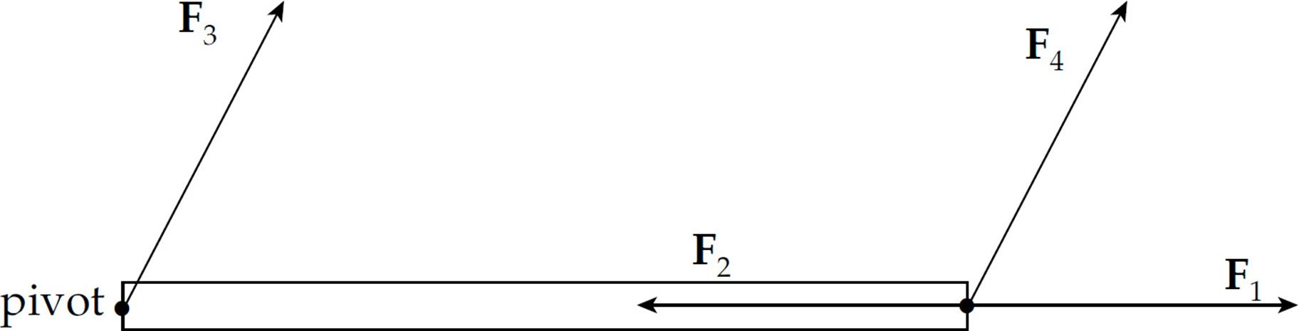
Our intuition tells us that F1, F2, and F3 would not cause the rod to rotate, but F4 would. What’s different about F4? It has torque. Clearly, torque has something to do with rotation. Just like a force is a vector quantity that produces linear acceleration, a torque is a vector quantity that produces angular acceleration. Note that, just like for linear acceleration, an angular acceleration is something that either changes the direction of the angular velocity or changes the angular speed. A torque can be thought of as being positive if it produces counterclockwise rotation, or negative if it produces clockwise rotation.
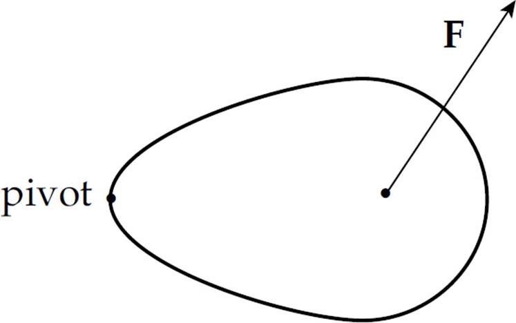
The torque of a force can be defined as follows. Let r be the distance from the pivot (axis of rotation) to the point of application of the force F, and let θ be the angle between vectors r and F.
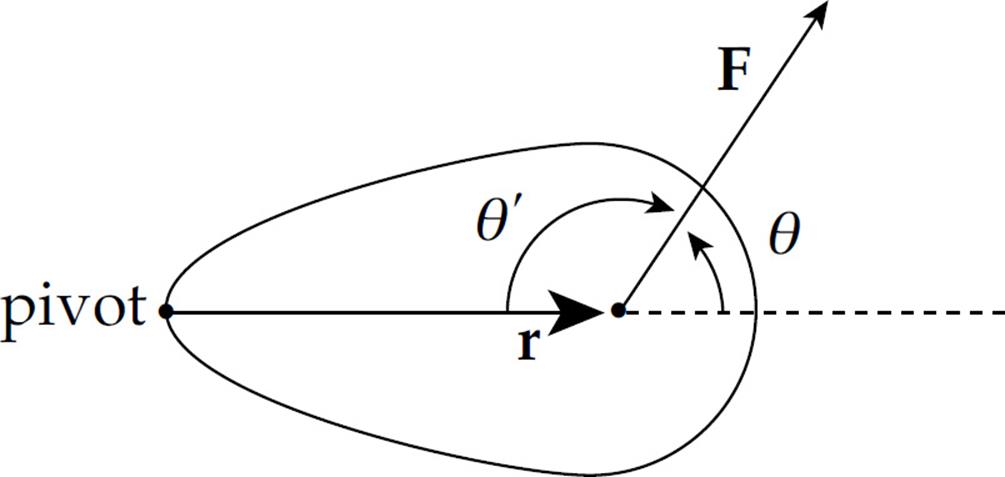
Then the torque of F, denoted by τ (tau), is defined as:
τ = rF sin θ
In the figure above, the angle between the vectors r and F is θ. Imagine sliding r over so that its initial point is the same as that of F. The angle between two vectors is the angle between them when they start at the same point. However, the supplementary angle θ’ can be used in place of θin the definition of torque. This is because torque depends on sin θ, and the sine of an angle and the sine of its supplement are always equal. Therefore, when figuring out torque, use whichever of these angles is more convenient.
We will now see if this mathematical definition of torque supports our intuition about forces F1, F2, F3, and F4.
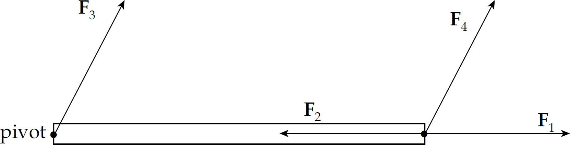
The angle between r and F1 is 0, and θ = 0 implies sin θ = 0, so by the definition of torque, τ = 0 as well. The angle between r and F2 is 180°, and θ = 180° gives us sin θ = 0, so τ = 0. For F3, r = 0 (because F3 acts at the pivot, so the distance from the pivot to the point of application of F3is zero); since r = 0, the torque is 0 as well. However, for F4, neither r nor sin θ is zero, so F4 has a nonzero torque. Of the four forces shown in that figure, only F4 has torque and would produce rotational acceleration.
There’s another way to determine the value of the torque. Of course, it gives the same result as the method given above, but this method is often easier to use. Look at the same object and force:
Instead of determining the distance from the pivot point to the point of application of the force, we will now determine the (perpendicular) distance from the pivot point to what’s called the line of action of the force. This distance is the lever arm (or moment arm) of the force F relative to the pivot, and is denoted by l.
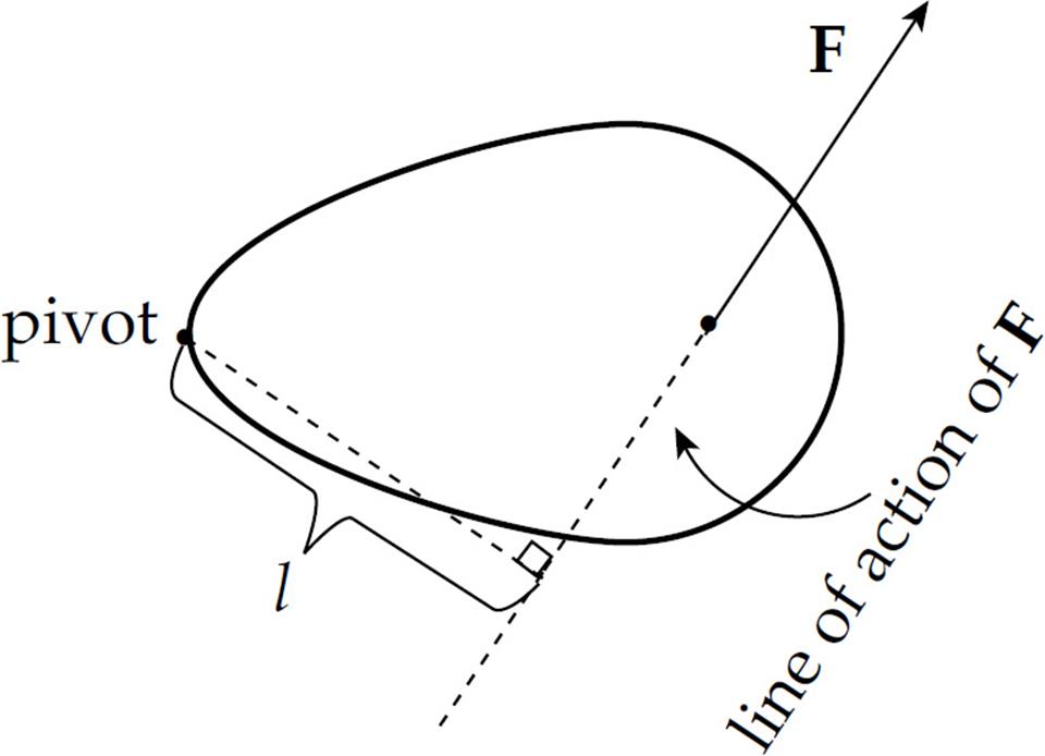
The torque of F is defined as the product
τ = lF
Just as the lever arm is often called the moment arm, the torque is called the moment of the force. That these two definitions of torque, τ = rF sin θ and τ = lF are equivalent follows immediately from the fact that l = r sin θ:
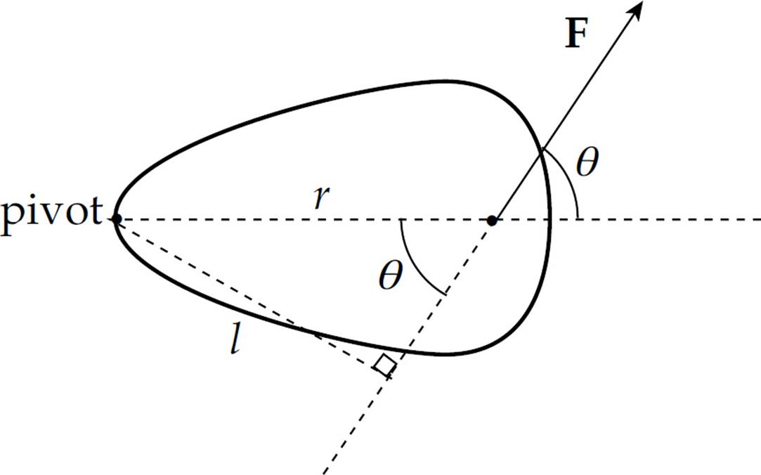
Since l is the component of r that’s perpendicular to F, it is also denoted by r⊥ (“r perp”). So the definition of torque can be written as τ = r⊥F.
These two equivalent definitions of torque make it clear that only the component of F that’s perpendicular to r produces torque. The component of F that’s parallel to r does not produce torque. Notice that τ = rF sin θ = rF⊥, where F⊥ (“F perp”) is the component of F that’s perpendicular to r:
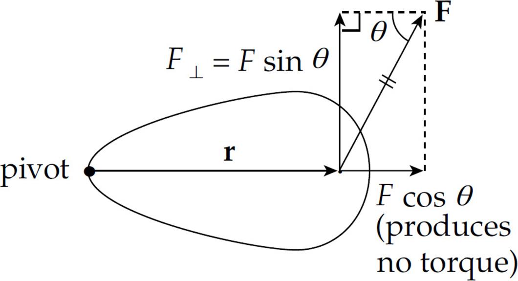
So the definition of torque can also be written as τ = rF⊥.
Also, since only the component of F (perpendicular to r) produces torque, the torque can be written as the cross product of r and F, and this is how it appears on the free-response equation sheet:
![]()
Example 8 A student pulls down with a force of 40 N on a rope that winds around a pulley of radius 5 cm.
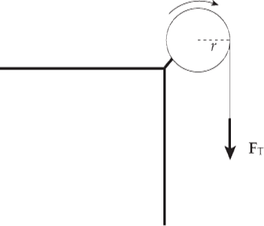
What’s the torque of this force?
Solution. Since the tension force, FT, is tangent to the pulley, it is perpendicular to the radius vector r at the point of contact:
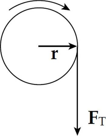
Therefore, the torque produced by this tension force is simply
τ = rFT = (0.05 m)(40 N) = 2 N·m
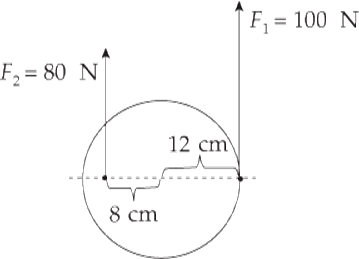
Example 9 What is the net torque on the cylinder shown below? The cylinder is pinned at its center.
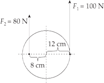
Solution. Each of the two forces produces a torque, but these torques oppose each other. The torque of F1 is counterclockwise, and the torque of F2 is clockwise. This can be visualized either by imagining the effect of each force, assuming that the other was absent, or by using the vector definition of torque, τ = r × F. In the case of F1, we have, by the right-hand rule,
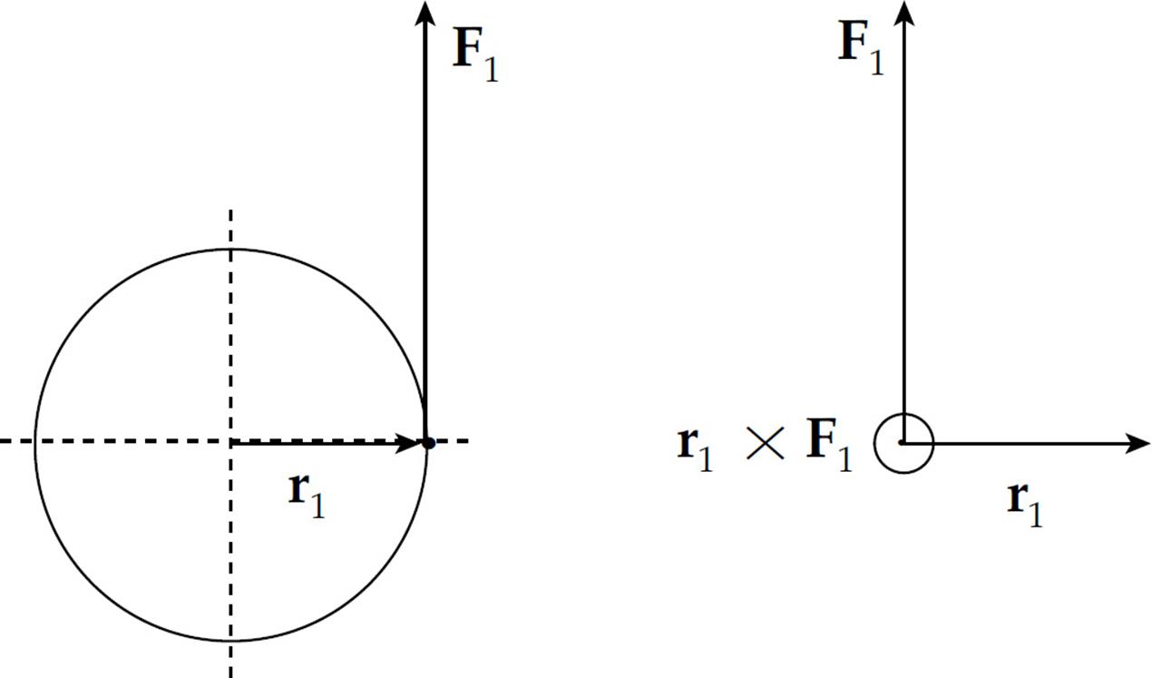
τ1 = r1 × F1 points out of the plane of the page:  , while
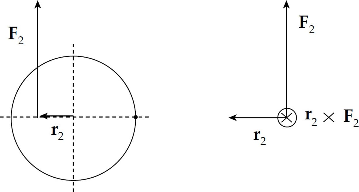
τ2 = r2 × F2 points into the plane of the page: 
These symbols are easy to remember if you think of a dart: is the point of the dart coming at you and is the pattern of feathers at the back of the dart you see as it flies away from you toward the dartboard.
If the torque vector points out of the plane of the page, this indicates a tendency to produce counterclockwise rotation and, if it points into the plane of the page, this indicates a tendency to produce clockwise rotation.
The net torque is the sum of all the torques. Counting a counterclockwise torque as positive and a clockwise torque as negative, we have
τ1 = +r1F1 = +(0.12 m)(100 N) = +12 N•m
and
τ2 = –r2F2 = –(0.08 m)(80 N) = –6.4 N•m
so
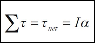
τnet = Στ = τ1 + τ2 = (+12 N·m) + (–6.4 N·m) = +5.6 N•m
ROTATIONAL INERTIA
Our goal is to develop a rotational analog of Newton’s Second Law, Fnet = ma. We’re almost there; torque is the rotational analog of force and, therefore, τnet is the rotational analog of Fnet. The rotational analog of translational acceleration, a, is rotational (or angular) acceleration, α. We will now look at the rotational analog of inertial mass, m.
Consider a small point mass m at a distance r from the axis of rotation, being acted upon by a tangential force F.
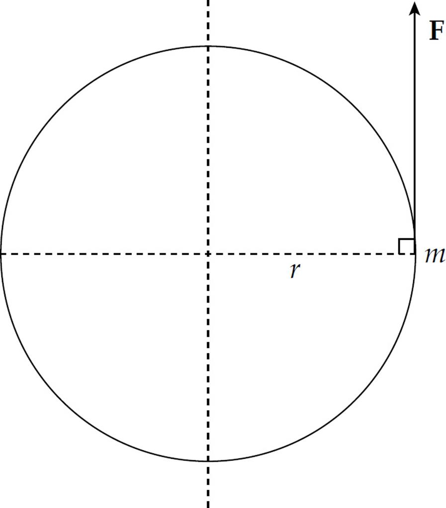
From Newton’s Second Law, we have F = ma. Substituting a = rα, this equation becomes F = mrα. Now multiply both sides of this last equation by r to yield
rF = mr2α
or, since rF = τ,
τ = mr2α
In the equation F = ma, the quantity m is multiplied by the acceleration produced by the force F, while in the equation τ = mr2α, the quantity mr2 is multiplied by the rotational acceleration produced by the torque τ.
So for a point mass at a distance r from the axis of rotation, its rotational inertia (also called moment of inertia) is defined as mr2. If we now take into account all the point masses that comprise the object under study, we can get the total rotational inertia, I, of the body by adding them:
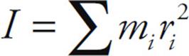
For a continuous solid body, this sum becomes the integral
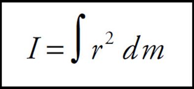
This formula can be used to calculate expressions for the rotational inertia of cylinders (disks), spheres, slender rods, and hoops. Notice that the rotational inertia depends not only on m, but also on r; both the mass and how it’s distributed about the axis of rotation determine I. By summing over all point masses and all external torques, the equation τ = mr2α becomes
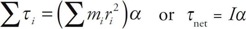
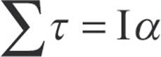
On the equation sheet for the free-response section, this information will be represented as follows:
We’ve reached our goal:
|
Translational motion |
Rotational motion |
|
force, F |
torque, τ |
|
acceleration, a |
rotational acceleration, α |
|
mass, m |
rotational inertia, I |
|
Fnet = ma |
τnet = Iα |
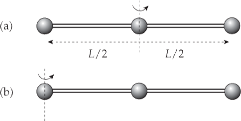
Example 10 Three beads, each of mass m, are arranged along a rod of negligible mass and length L. Figure out the rotational inertia of the assembly when the axis of rotation is through the center bead and when the axis of rotation is through one of the beads on the ends.
Solution.
(a) In the first case, both the left bead and the right bead are at a distance of L/2 from the axis of rotation, while the center bead is at distance zero from the axis of rotation. Therefore,

(b) In the second case, the left bead is at distance zero from the rotation axis, the center bead is at distance L/2, and the right bead is at distance L. Therefore,

Note that, although both assemblies have the same mass (namely, 3m), their rotational inertias are different, because of the different distribution of mass relative to the axis of rotation.
If the rotational inertia of a body is known relative to an axis that passes through the body’s center of mass, then the rotational inertia, I’, relative to any other rotation axis (parallel to the first one) can be calculated as follows. Let Icm be the rotational inertia of a body relative to a rotation axis that passes through the body’s center of mass, let the mass of the body be M, and let x be the distance from the axis through the center of mass to the rotation axis. Then
I = Icm + md2
This is called the parallel-axis theorem. Let’s use this result to calculate the rotational inertia of the three-bead assembly in part (b) from the value obtained in part (a), which is Icm. Since M = 3m and x = L/2, we have

which agrees with the value calculated above.
Example 11 Show that the rotational inertia of a homogeneous cylinder of radius R and mass M, rotating about its central axis, is given by the equation I = ![]() MR2.
MR2.
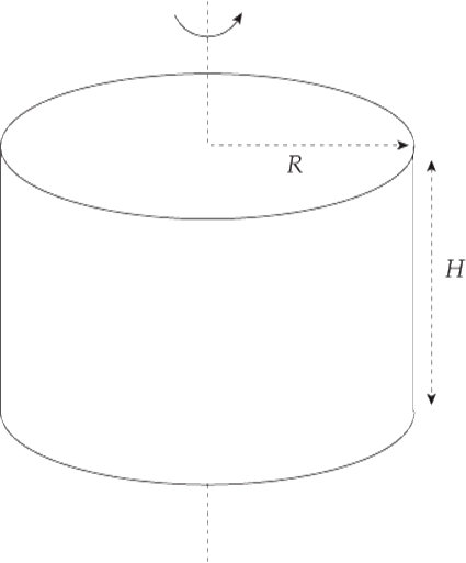
Solution. A solid is homogeneous if its density is constant throughout. Let ρ be the density of the cylinder. In order to compute I using the formula I = ![]() r2 dm we choose our mass element to be an infinitesimally thin cylindrical ring of radius r:
r2 dm we choose our mass element to be an infinitesimally thin cylindrical ring of radius r:
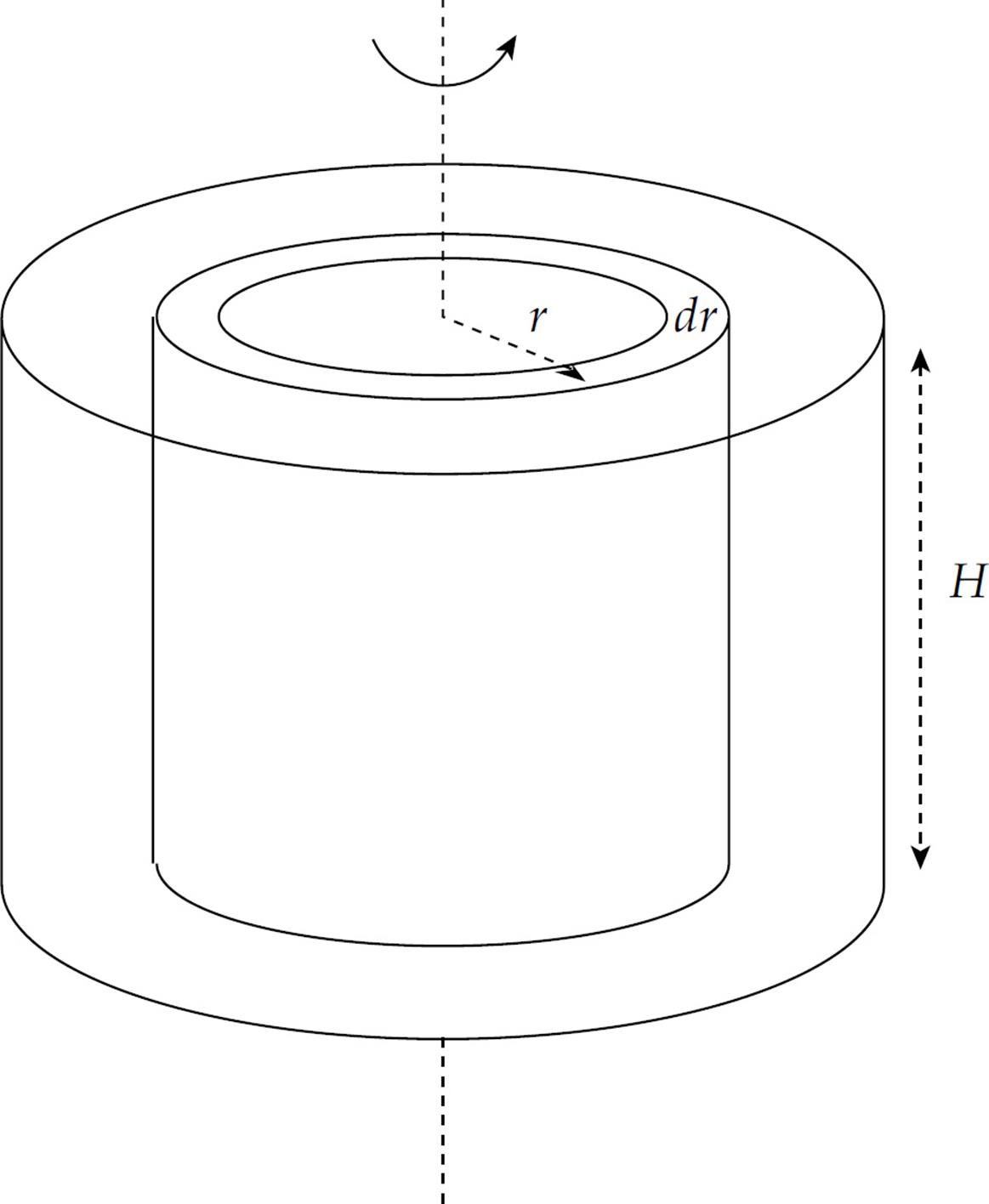
The mass of this ring is equal to its volume, 2πr dr × H, times the density; that is,
dm = ρ × 2πrH dr
Therefore,
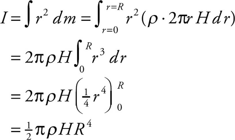
To eliminate ρ, use the fact that the total mass of the cylinder is
M = ρV = ρ · πR2H
Putting this into the expression derived for I, we find that

The height of the cylinder (the dimension parallel to the axis of rotation) is irrelevant. Therefore, the formula I = ![]() MR2 gives the rotational inertia of any homogeneous solid cylinder revolving around its central axis. This includes a disk (which is just a really short cylinder).
MR2 gives the rotational inertia of any homogeneous solid cylinder revolving around its central axis. This includes a disk (which is just a really short cylinder).
Example 12 Again, consider the system of Example 9:
Assume that the mass of the cylinder is 50 kg. Given that the rotational inertia of a cylinder of radius R and mass M rotating about its central axis is given by the equation I = ![]() MR2, determine the rotational acceleration produced by the two forces shown.
MR2, determine the rotational acceleration produced by the two forces shown.
Solution. In Example 9, we figured out that τnet = +5.6 N·m. The rotational inertia of the cylinder is
I = ![]() MR2 =
MR2 = ![]() (50 kg)(0.12 m)2 = 0.36 kg·m2
(50 kg)(0.12 m)2 = 0.36 kg·m2
Therefore, from the equation τnet = Iα, we find that
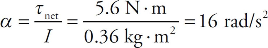
This angular acceleration will be counterclockwise, because τnet is counterclockwise.
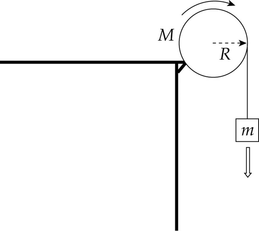
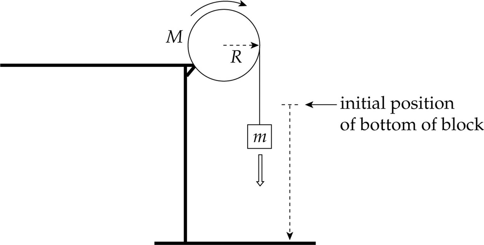
Example 13 A block of mass m is hung from a pulley of radius R and mass M and allowed to fall. What is the acceleration of the block?
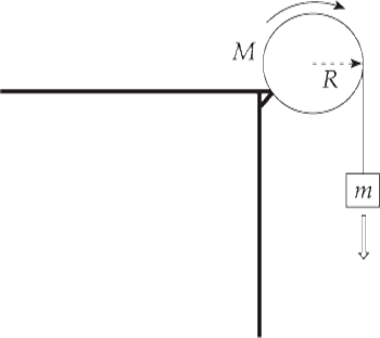
Solution. Remember that earlier, we treated pulleys as if they were massless, and no force was required to make them rotate. Now, however, we know how to take the mass of a pulley into account, by including its rotational inertia in our analysis. The pulley is a disk, so its rotational inertia is given by the formula I = ![]() MR2.
MR2.
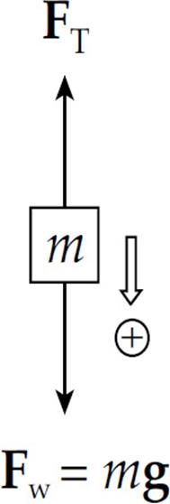
First we draw a free-body diagram for the falling block:
and apply Newton’s Second Law:
mg – FT = ma (1)
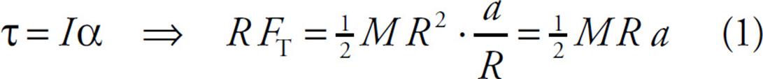
Now the tension FT in the cord produces a torque, τ = RFT, on the pulley:
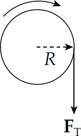
Since this is the only torque on the pulley, the equation τnet = Iα becomes RFT = Iα. But I = ![]() MR2 and α = a/R. Therefore,
MR2 and α = a/R. Therefore,
which tells us that
FT = ![]() Ma (2)
Ma (2)
Substituting Equation (2) into Equation (1), we find that

This last equation says that
the cord doesn’t slip as it
slides over the pulley; the
linear acceleration of a
point on the rim, a = Rα, is
equal to the acceleration
of the connected block.
KINETIC ENERGY OF ROTATION
A rotating object has rotational kinetic energy, just as a translating object has translational kinetic energy. The formula for kinetic energy is, of course, K = ![]() mv2, but this can’t be directly used to calculate the kinetic energy of rotation because each point mass that makes up the body can have a different v. For this reason, we need a definition of Krotational that involves ω instead of v.
mv2, but this can’t be directly used to calculate the kinetic energy of rotation because each point mass that makes up the body can have a different v. For this reason, we need a definition of Krotational that involves ω instead of v.

In short, then:
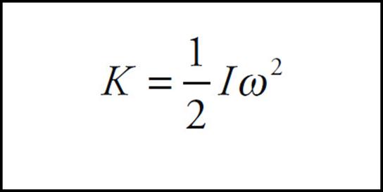
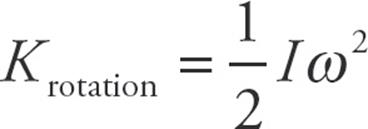
Note that this expression for rotational kinetic energy follows the general pattern displayed by our previous results: I is the rotational analog of m and ω is the rotational analog of v. Therefore, the rotational analog of ![]() mv2 should be
mv2 should be ![]() Iω2.
Iω2.
Rolling Motion
One of the main types of motion associated with rotational motion is rolling motion. We will primarily deal with rolling without slipping.
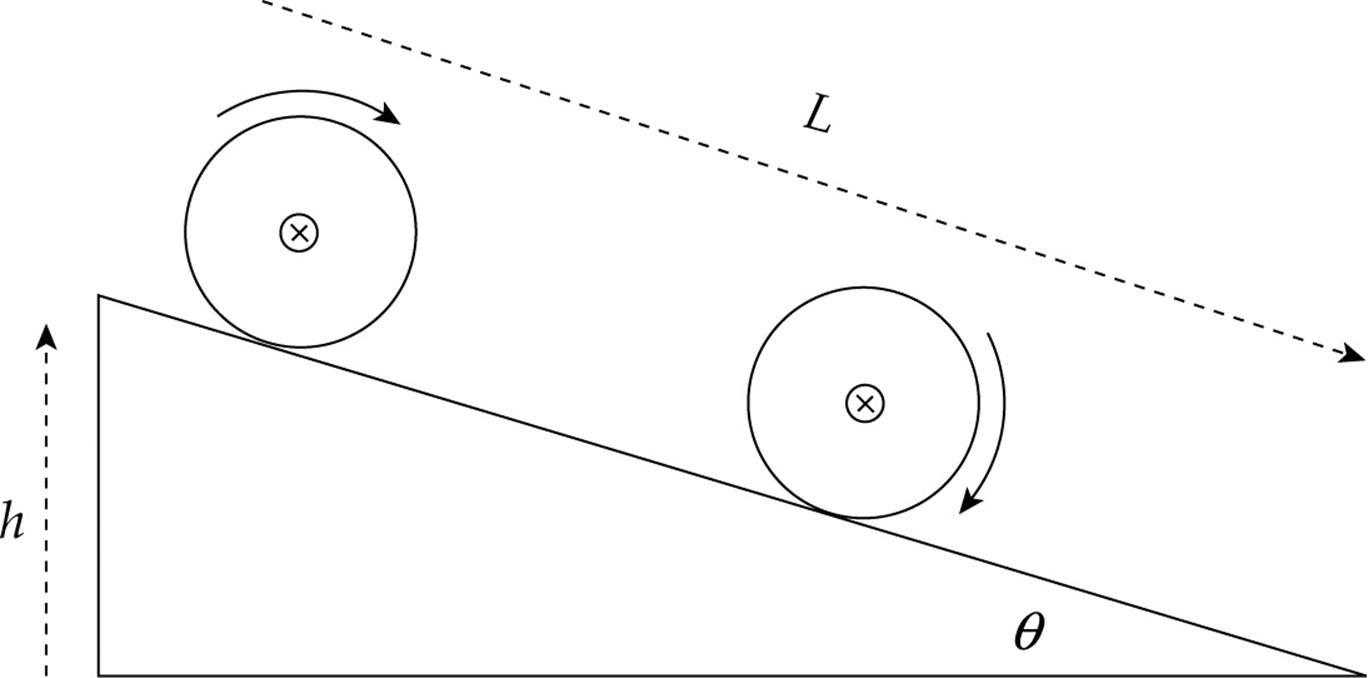
Consider a disk rolling down an incline without slipping.
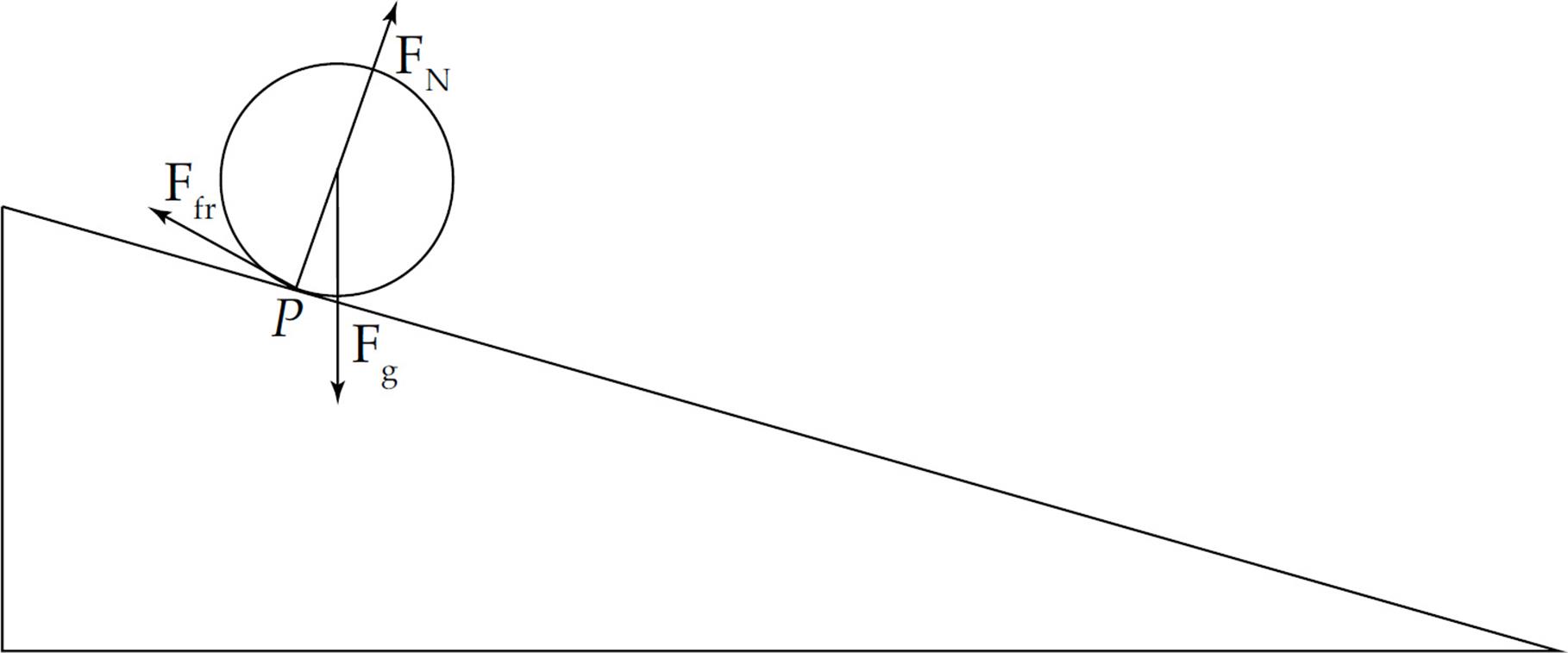
The point of contact of the object with the surface P is instantaneously at rest. If this were not the case then the disk would be slipping down the incline, so the contact point must not be moving relative to the surface. In this case, the velocity of the center of mass of the disk is equal to the radius times the angular velocity of the disk.
You can take the torque around any point to determine the acceleration of the disk. It is often easiest to take it around the contact point P because then only gravity provides a torque about this point, and if you know the mass of the object, then you know the force of gravity. Make sure to use the parallel-axis theorem in this case since you are considering the rotational inertia about point P, not the center of mass. This will allow you to calculate the acceleration of the disk. Once you know the acceleration, you can calculate the necessary coefficient of friction to produce rolling without slipping using Newton’s Second Law.
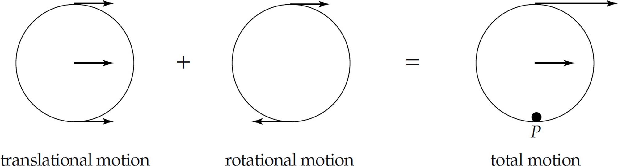
The total motion for an object that is rolling without slipping is the combined motion of the entire object translating with the velocity of the center of mass, and the object rotating about its center of mass, as shown below. This shows the object is instantaneously rotating about the contact point P.
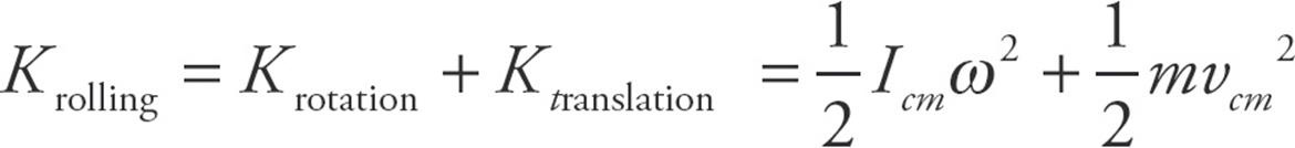
For rolling motion the total kinetic energy is the translational kinetic energy and the rotational kinetic energy.
Example 14 A cylinder of mass M and radius R rolls (without slipping) down an inclined plane whose incline angle with the horizontal is θ. Determine the acceleration of the cylinder’s center of mass, and the minimum coefficient of friction that will allow the cylinder to roll without slipping on this incline.
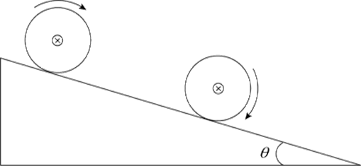
Solution. First we draw a free-body diagram for the cylinder:
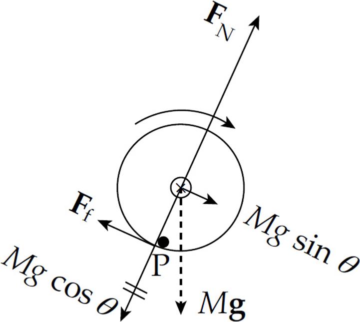
We know that the cylinder rolls without slipping, so the force of friction is not kinetic friction. Since the speed of the point on the cylinder in contact with the ramp is zero with respect to the ramp, static friction supplies the torque that allows the cylinder to roll smoothly.
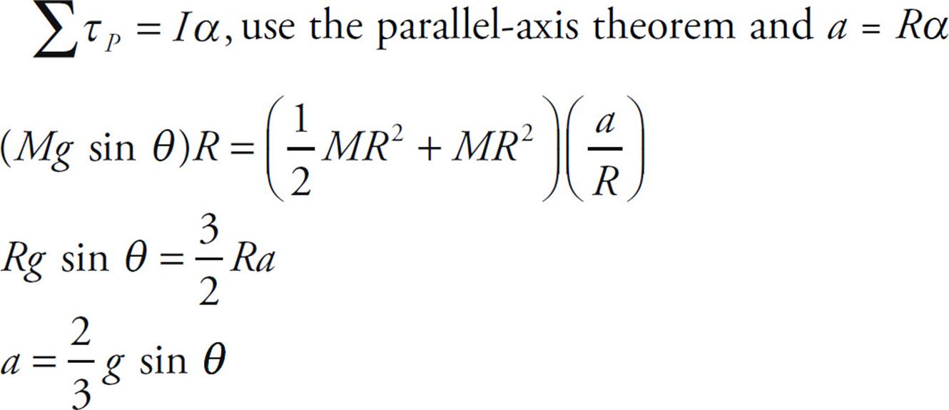
Take the torque about the contact point to solve for the acceleration because the frictional force will not be part of the equation and we do not know it yet.
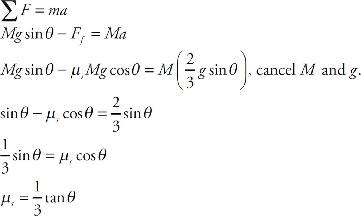
Now we will use Newton’s Second Law to solve for µs since we know the acceleration.
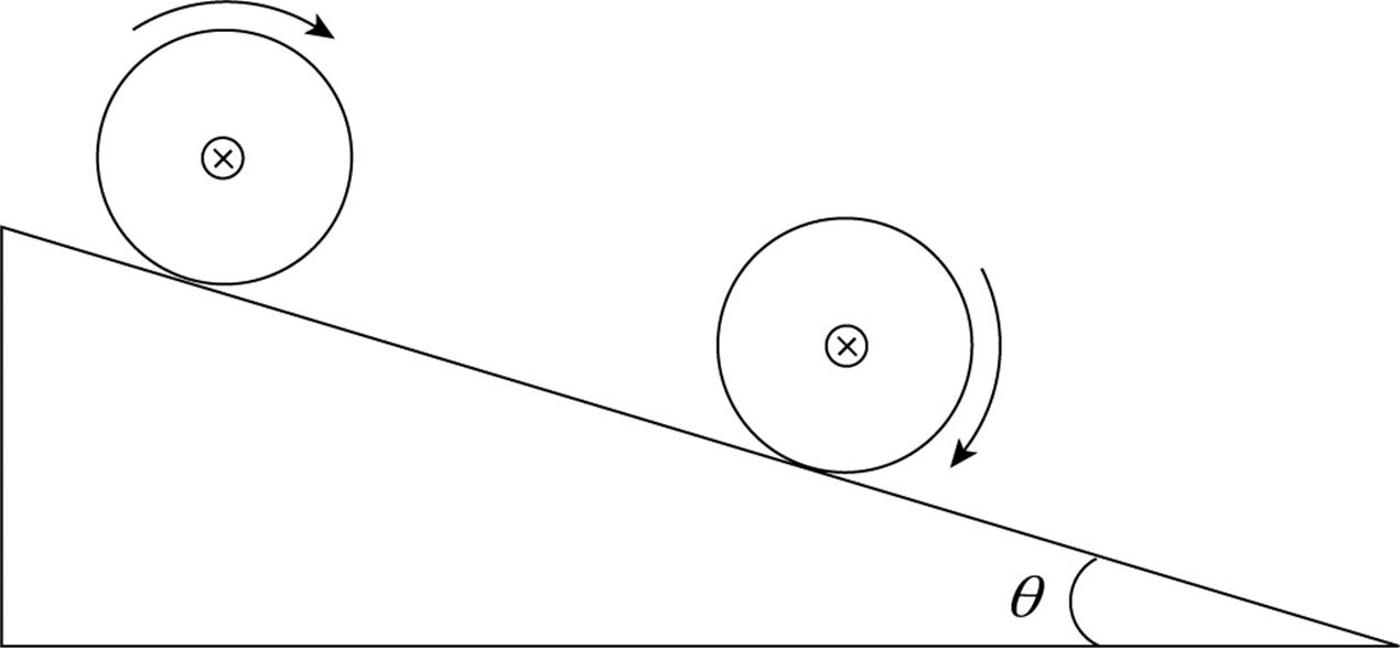
Example 15 A cylinder of mass M and radius R rolls (without slipping) down an inclined plane (of height h and length L) whose incline angle with the horizontal is θ. Determine the linear speed of the cylinder’s center of mass when it reaches the bottom of the incline (assuming that it started from rest at the top).
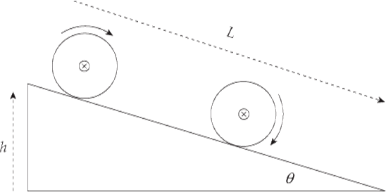
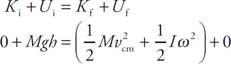
Solution. We will attack this problem using Conservation of Mechanical Energy. As the cylinder rolls down the ramp, its initial gravitational potential energy is converted into kinetic energy, which is a combination of translational kinetic energy (since the cylinder’s center of mass is translating down the ramp) and rotational kinetic energy:
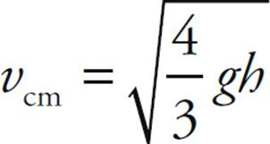
Since I = ![]() MR2 and ω = vcm/R, this equation becomes
MR2 and ω = vcm/R, this equation becomes

Therefore,
We can verify this result using the result of the previous example. There we found that the acceleration of the cylinder’s center of mass as it rolled down the ramp was a = ![]() g sin θ. Applying Big Five #5 gives us:
g sin θ. Applying Big Five #5 gives us:

WORK AND POWER
Consider a small point mass m at distance r from the axis of rotation, acted upon by a tangential force F.
As it rotates through an angular displacement of θ, the force does work on the point mass: W = Fs, where s = rθ. Therefore,
W = Fr θ = τ θ
If the force is not purely tangential to the object’s path, then only the tangential component of the force does work; the radial component does not (since it’s perpendicular to the object’s displacement). Therefore, for a general constant force F, the equation above would read W = Ftrθ = τ θ, where Ft denotes the tangential component of F.
If we want to allow for a varying F—and a varying τ—then the work done is equal to the definite integral:
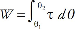
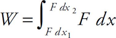
Again, notice the analogy between this equation and the one that defines work by F:
The work–energy theorem (W = K) also holds in the rotational case, where W is the work done by net torque and K is the resulting change in the rotational kinetic energy.
The rate at which work is done, or the power (P), is defined by the equation
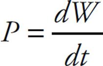
Over an infinitesimal angular displacement dθ, the torque τ does an amount of work dW given by dW = τ dθ. This implies that
Once again, notice the parallel to P = Fv, the translation version of this equation.
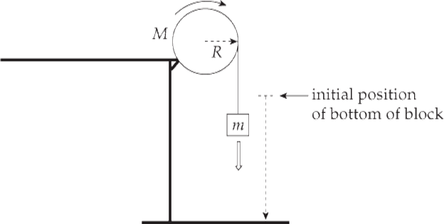
Example 16 A block of mass m = 5 kg is hung from a pulley of radius R = 15 cm and mass M = 8 kg and then released from rest.
(a) What is the speed of the block as it strikes the floor, 2 m below its initial position?
(b) What is the rotational kinetic energy of the pulley just before the block strikes the floor?
(c) At what rate was work done on the pulley?
Solution.
(a) Apply Conservation of Mechanical Energy. The initial gravitational potential energy of the block is transformed into the purely rotational kinetic energy of the pulley and translational kinetic energy of the falling block:
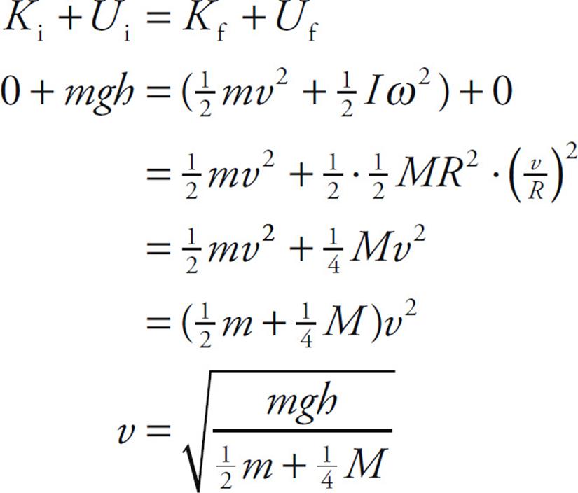
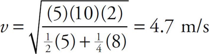
Substituting in the given numerical values, we get
(b) The rotational kinetic energy of the pulley as the block strikes the floor is

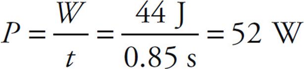
(c) The rate at which work is done on the pulley is the power produced by the torque. One way to compute this is to first use the work–energy theorem to determine the work done by the torque and then divide this by the time during which the block fell. So,
W = K = Kfi − K = Kf = 44 J
The time during which this work was done is the time required for the block to drop to the ground. Using Big Five #1 and the result of part (a), we find that

Therefore,
ANGULAR MOMENTUM
So far we’ve developed rotational analogs for displacement, velocity, acceleration, force, mass, and kinetic energy. We will finish by developing a rotational analog for linear momentum; it’s called angular momentum.
Consider a small point mass m at distance r from the axis of rotation, moving with velocity v and acted upon by a tangential force F.
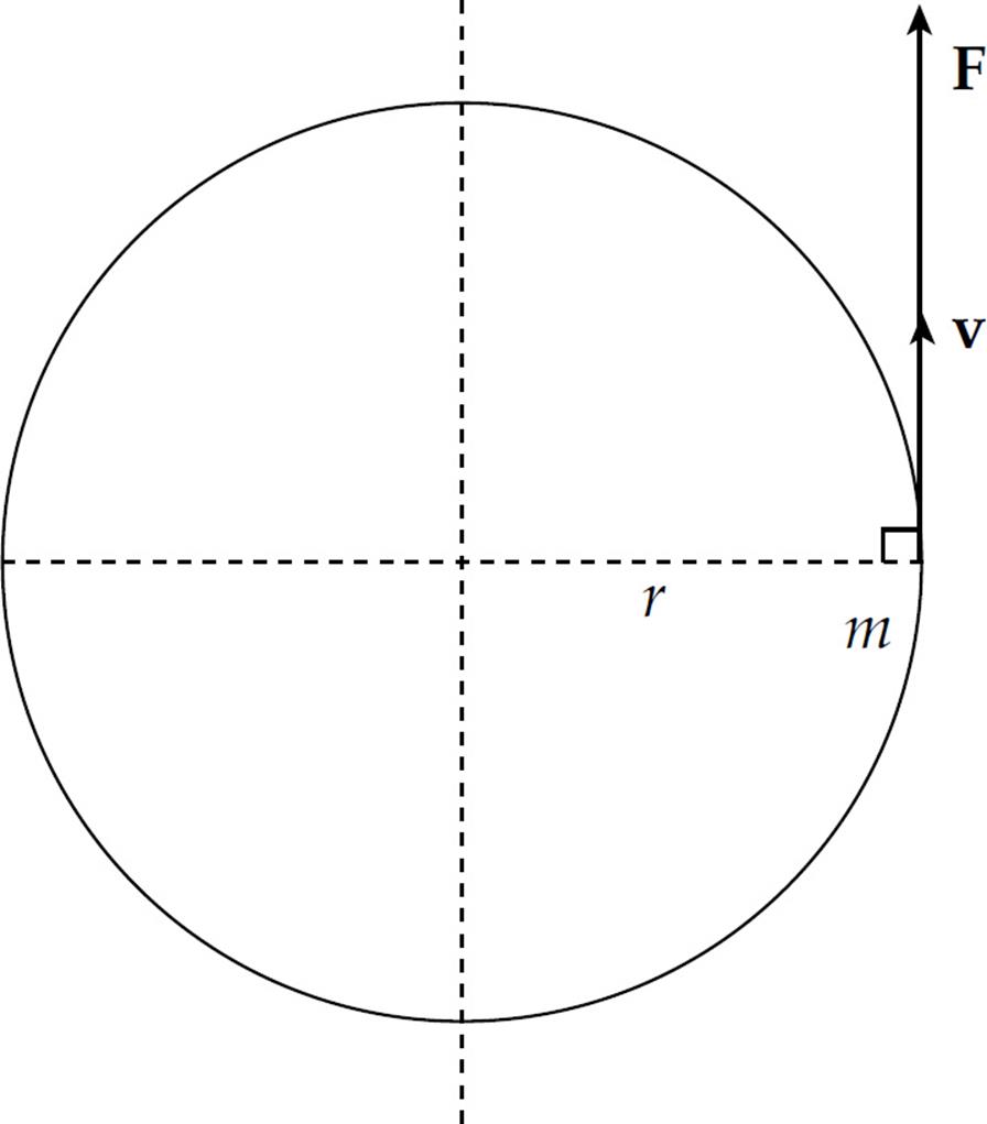
Then, by Newton’s Second Law,
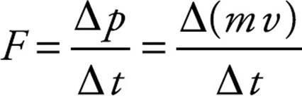
If we multiply both sides of this equation by r and notice that rF = τ, we get
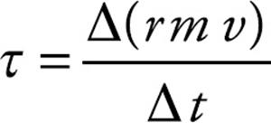
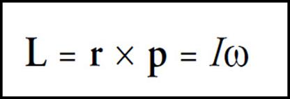
Therefore, to form the analog of the law F = p/t (force equals the rate-of-change of linear momentum), we say that torque equals the rate-of-change of angular momentum, and the angular momentum (denoted by L) of the point mass m is defined by the equation
L = rmv
If we now take into account all the point masses that comprise the object under study, we can get the angular momentum of the body by adding up all the individual contributions. This gives
L = Iω
Note that this expression for angular momentum follows the general pattern we saw previously: I is the rotational analog of m, and ω is the rotational analog of v. Therefore, the rotational analog of mv should be Iω.
If the point mass m does not move in a circular path, we can still define its angular momentum relative to any reference point.
If r is the vector from the reference point to the mass, then the angular momentum is
L = rmv⊥
where v⊥ is the component of the velocity that’s perpendicular to r. This is the perpendicular component of v relative to r that’s important for figuring out angular momentum, and this fact leads to the general vector definition with the cross product. The equation L = (r)(mv⊥) = (r)(p⊥) becomes
Example 17 A solid uniform sphere of mass M = 8 kg and radius R = 50 cm is revolving around an axis through its center at an angular speed of 10 rad/s. Given that the rotational inertia of the sphere is equal to ![]() MR2, what is the spinning sphere’s angular momentum?
MR2, what is the spinning sphere’s angular momentum?
Solution. Apply the definition:
L = Iω = ![]() MR2ω =
MR2ω = ![]() (8 kg)(0.50 m)2(10 rad / s) = 8 kg · m2 / s
(8 kg)(0.50 m)2(10 rad / s) = 8 kg · m2 / s
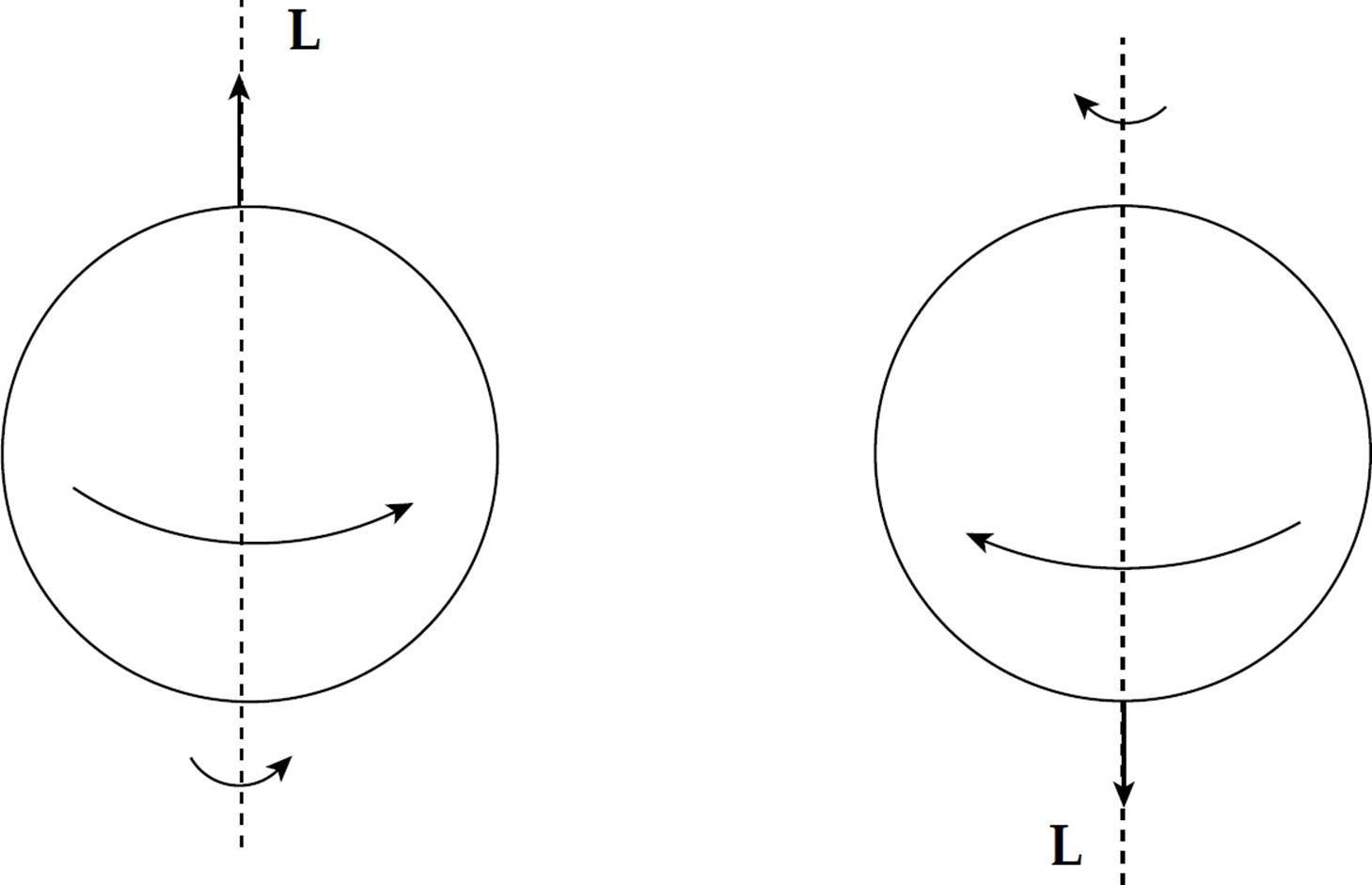
If you want to specify the direction of the angular momentum vector, L, use the right-hand rule. Let the fingers of your right hand curl in the direction of rotation of the body. Your thumb gives the direction of L, pointing along the rotation axis:
CONSERVATION OF ANGULAR MOMENTUM
Newton’s Second Law says that
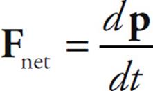
so if Fnet = 0, then p is constant. This is Conservation of Linear Momentum.
The rotational analog of this is:
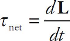
So if τnet = 0, then L is constant. This is Conservation of Angular Momentum. Basically, this says that if the torques on a body balance so that the net torque is zero, then the body’s angular momentum can’t change.
An often cited example of this phenomenon is the spinning of a figure skater. As she pulls her arms inward, she moves more of her mass closer to the rotation axis and decreases her rotational inertia. Since the external torque on her is negligible, her angular momentum must be conserved. Since L = Iω, a decrease in I causes an increase in ω, and she spins faster.
Example 18 A child of mass m = 30 kg stands at the edge of a small merry-go-round that’s rotating at a rate of 1 rad/s. The merry-go-round is a disk of radius R = 2.5 m and mass M = 100 kg. If the child walks in toward the center of the disk and stops 0.5 m from the center, what will happen to the angular velocity of the merry-go-round (if friction can be ignored)?
Solution. The child walking toward the center of the merry-go-round does not provide an external torque to the child + disk system, so angular momentum is conserved. Let’s denote the child as a point mass, and consider the following two views of the merry-go-round (looking down from above):
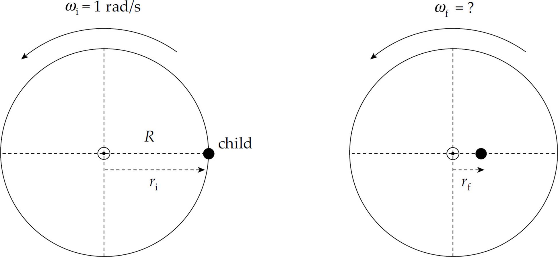
In the first picture, the total rotational inertia, Ii, is equal to the sum of the rotational inertia of the merry-go-round (MGR) and the child:

In the second picture, the total rotational inertia has decreased to

So, by Conservation of Angular Momentum, we have
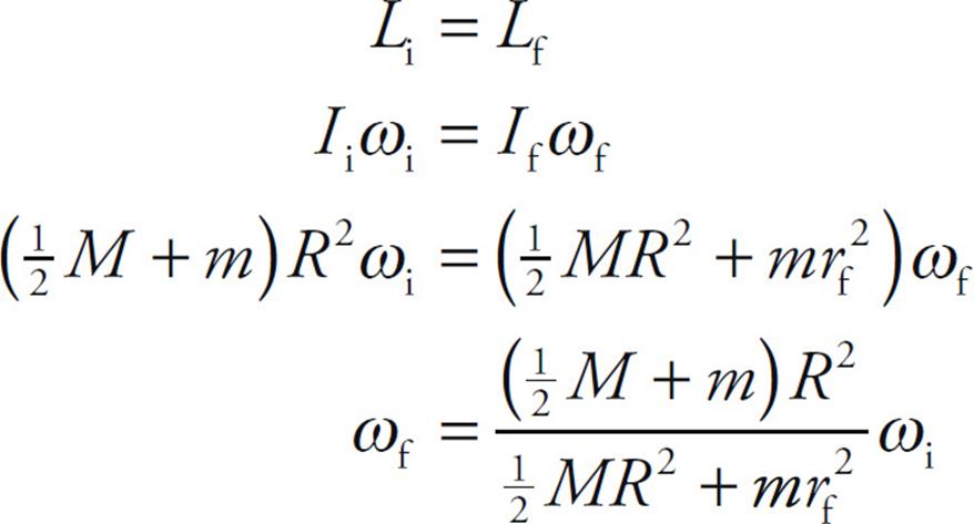
and substituting the given numerical values gives us
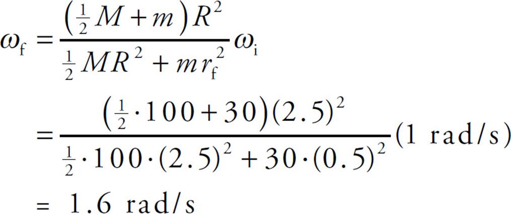
Notice that ω increased as I decreased, just as Conservation of Angular Momentum predicts.
EQUILIBRIUM
An object is said to be in translational equilibrium if the sum of the forces acting on it is zero; that is, if Fnet = 0. Similarly, an object is said to be in rotational equilibrium if the sum of the torques acting on it is zero; that is, if τnet = 0. The term equilibrium by itself means both translational and rotational equilibrium. A body in equilibrium may be in motion; Fnet = 0 does not mean that the velocity is zero; it only means that the velocity is constant. Similarly, τnet = 0 does not mean that the angular velocity is zero; it only means that it’s constant. If an object is at rest, then it is said to be in static equilibrium.
Example 19 A uniform bar of mass m and length L extends horizontally from a wall. A supporting wire connects the wall to the bar’s midpoint, making an angle of 55° with the bar. A sign of mass M hangs from the end of the bar.
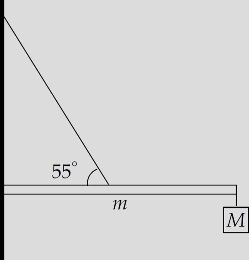
If the system is in static equilibrium, determine the tension in the wire and the strength of the force exerted on the bar by the wall if m = 8 kg and M = 12 kg.
Solution. Let FC denote the (contact) force exerted by the wall on the bar. In order to simplify our work, we can write FC in terms of its horizontal component, FCx, and its vertical component, FCy. Also, if FT is the tension in the wire, then FTx = FT cos 55° and FTy = FT sin 55° are its components. This gives us the following force diagram:
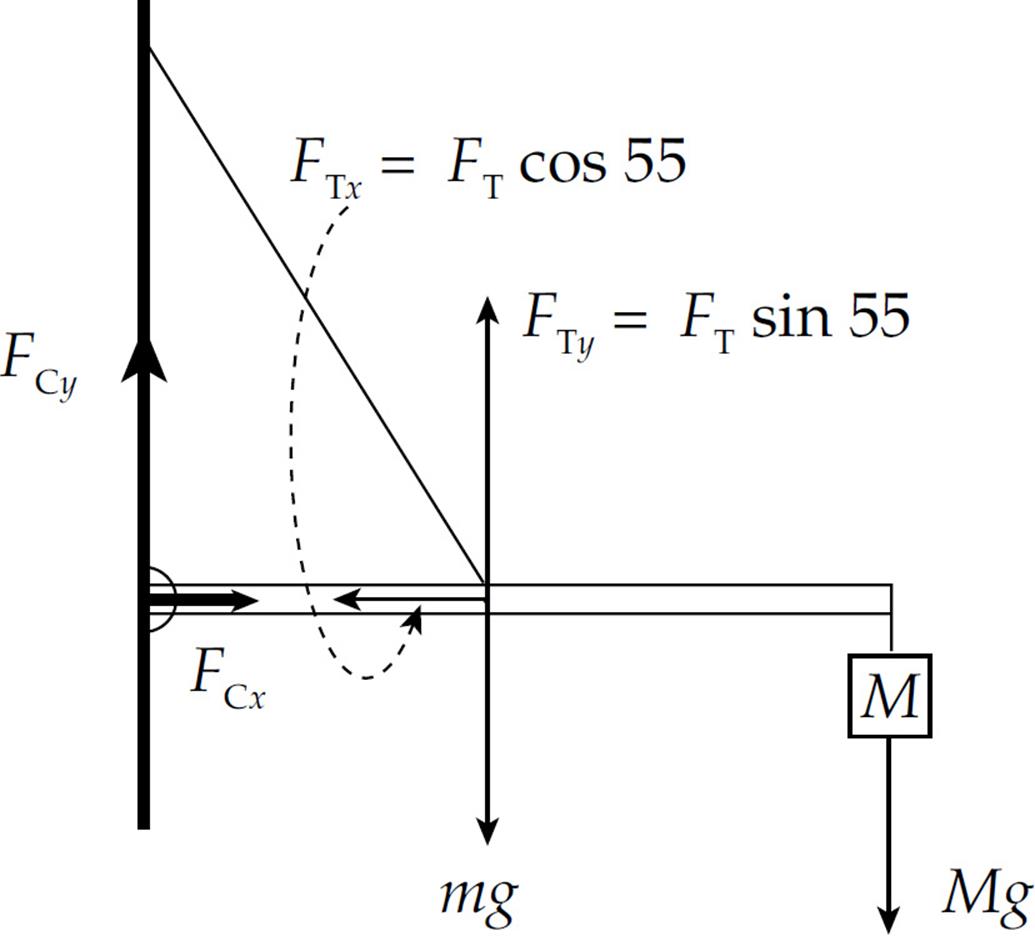
The first condition for equilibrium requires that the sum of the horizontal forces is zero and the sum of the vertical forces is zero:
ΣFx = 0: FCx – FT cos 55° = 0 (1)
ΣFy = 0: FCy + FT sin 55° – mg – Mg = 0 (2)
We notice immediately that we have more unknowns (FCx, FCy, FT) than equations, so this system cannot be solved as is. The second condition for equilibrium requires that the sum of the torques about any point is equal to zero. Choosing the contact point between the bar and the wall as our pivot, only three of the forces in the diagram above produce torque. FTy produces a counterclockwise torque, and both mg and Mg produce clockwise torques, which must balance. From the definition τ = lF, and taking counterclockwise torque as positive and clockwise torque as negative, we have
Στ = 0: (L/2)FTy – (L/2)(mg) – LMg = 0 (3)
This equation contains only one unknown and can be solved immediately:
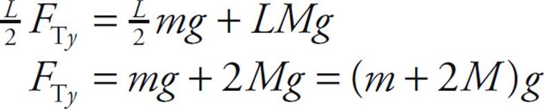
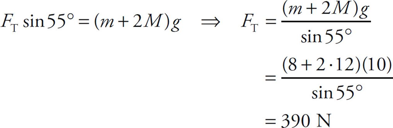
Since FTy = FT sin 55°, we can find that
Substituting this result into Equation (1) gives us FCx:

And finally, from Equation (2), we get
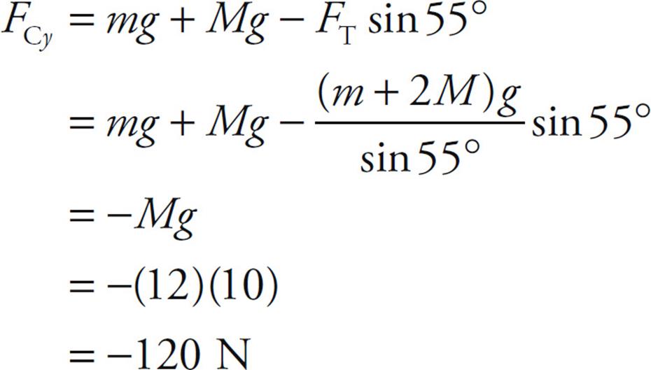
The fact that FCy turned out to be negative simply means that in our original force diagram, the vector FCy points in the direction opposite to how we drew it. That is, FCy points downward. Therefore, the magnitude of the total force exerted by the wall on the bar is

CHAPTER 8 REVIEW QUESTIONS
The answers and explanations can be found in Chapter 16.
Section I: Multiple Choice
1. A compact disc has a radius of 6 cm. If the disc rotates about its central axis at an angular speed of 5 rev/s, what is the linear speed of a point on the rim of the disc?
(A) 0.3 m/s
(B) 1.9 m/s
(C) 7.4 m/s
(D) 52 m/s
(E) 83 m/s
2. A compact disc has a radius of 6 cm. If the disc rotates about its central axis at a constant angular speed of 5 rev/s, what is the total distance traveled by a point on the rim of the disc in 40 min?
(A) 180 m
(B) 360 m
(C) 540 m
(D) 720 m
(E) 4.5 km
3. An object of mass 0.5 kg, moving in a circular path of radius 0.25 m, experiences a centripetal acceleration of constant magnitude 9 m/s2. What is the object’s angular speed?
(A) 2.3 rad/s
(B) 4.5 rad/s
(C) 6 rad/s
(D) 12 rad/s
(E) Cannot be determined from the information given
4. An object, originally at rest, begins spinning under uniform angular acceleration. In 10 s, it completes an angular displacement of 60 rad. What is the numerical value of the angular acceleration?
(A) 0.3 rad/s2
(B) 0.6 rad/s2
(C) 1.2 rad/s2
(D) 2.4 rad/s2
(E) 3.6 rad/s2
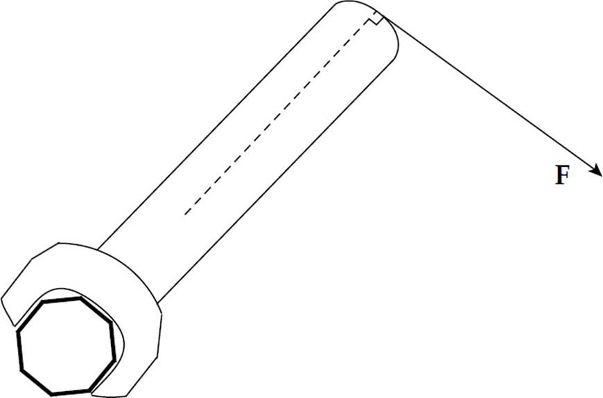
5. In an effort to tighten a bolt, a force F is applied as shown in the figure above. If the distance from the end of the wrench to the center of the bolt is 20 cm and F = 20 N, what is the magnitude of the torque produced by F?
(A) 0 N•m
(B) 1 N•m
(C) 2 N•m
(D) 4 N•m
(E) 10 N•m
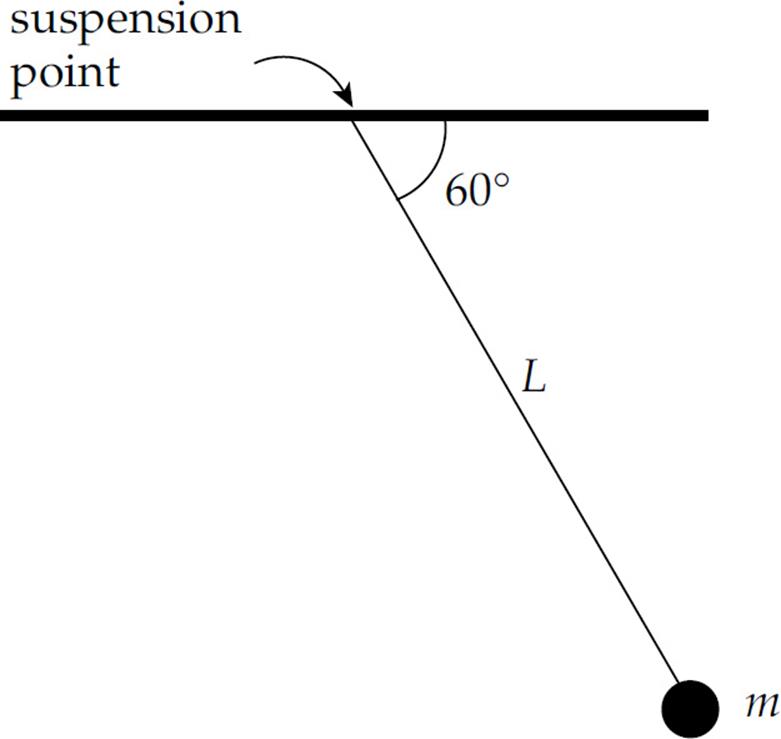
6. In the figure above, what is the torque about the pendulum’s suspension point produced by the weight of the bob, given that the length of the pendulum, L, is 80 cm and m = 0.50 kg?
(A) 0.5 N•m
(B) 1.0 N•m
(C) 1.7 N•m
(D) 2.0 N•m
(E) 3.4 N•m
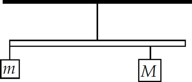
7. A uniform meter stick of mass 1 kg is hanging from a thread attached at the stick’s midpoint. One block of mass m = 3 kg hangs from the left end of the stick, and another block, of unknown mass M, hangs below the 80 cm mark on the meter stick. If the stick remains at rest in the horizontal position shown above, what is M?
(A) 4 kg
(B) 5 kg
(C) 6 kg
(D) 8 kg
(E) 9 kg
8. What is the rotational inertia of the following body about the indicated rotation axis? (The masses of the connecting rods are negligible.)
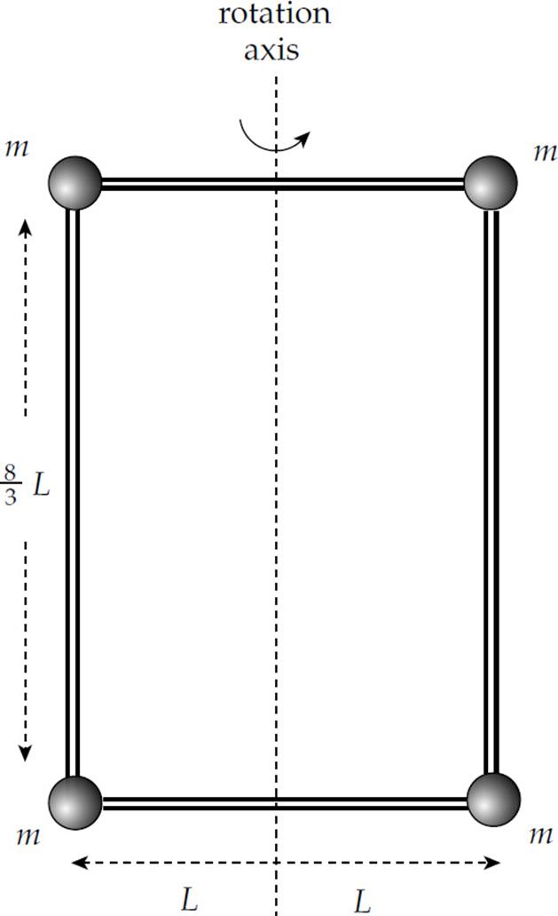
(A) 4mL2
(B)  mL2
mL2
(C)  mL2
mL2
(D)  mL2
mL2
(E)  mL2
mL2
9. The moment of inertia of a solid uniform sphere of mass M and radius R is given by the equation I = ![]() MR2. Such a sphere is released from rest at the top of an inclined plane of height h, length L, and incline angle θ. If the sphere rolls without slipping, find its speed at the bottom of the incline.
MR2. Such a sphere is released from rest at the top of an inclined plane of height h, length L, and incline angle θ. If the sphere rolls without slipping, find its speed at the bottom of the incline.
(A) 
(B) 
(C) 
(D) 
(E) 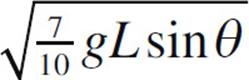
10. An object spins with angular velocity ω. If the object’s moment of inertia increases by a factor of 2 without the application of an external torque, what will be the object’s new angular velocity?
(A) ω/4
(B) ω/2
(C) ω/
(D) ω
(E) 2ω
Section II: Free Response
1. In the figure below, the pulley is a solid disk of mass M and radius R, with rotational inertia MR2/2. Two blocks, one of mass m1 and one of mass m2, hang from either side of the pulley by a light cord. Initially the system is at rest, with Block 1 on the floor and Block 2 held at height h above the floor. Block 2 is then released and allowed to fall. Give your answers in terms of m1, m2, M, R, h, and g.
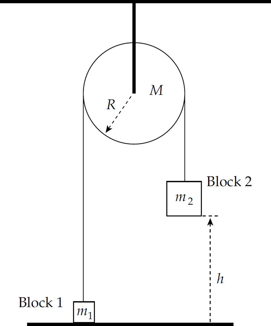
(a) What is the speed of Block 2 just before it strikes the ground?
(b) What is the angular speed of the pulley at this moment?
(c) What’s the angular displacement of the pulley?
(d) How long does it take for Block 2 to fall to the floor?
2. The diagram below shows a solid uniform cylinder of radius R and mass M rolling (without slipping) down an inclined plane of incline angle θ. A thread wraps around the cylinder as it rolls down the plane and pulls upward on a block of mass m. Ignore the rotational inertia of the pulley.
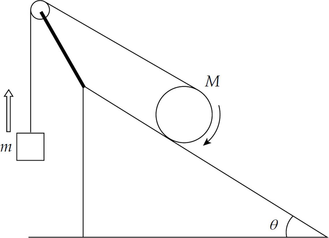
(a) Show that “rolling without slipping” means that the speed of the cylinder’s center of mass, vcm, is equal to Rω, where ω is its angular speed.
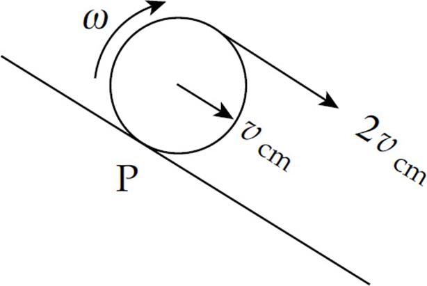
(b) Show that, relative to P (the point of contact of the cylinder with the ramp), the speed of the top of the cylinder is 2vcm.
(c) What is the relationship between the magnitude of the acceleration of the block and the linear acceleration of the cylinder?
(d) What is the acceleration of the cylinder?
(e) What is the acceleration of the block?
3. Two slender uniform bars, each of mass M and length 2L, meet at right angles at their midpoints to form a rigid assembly that’s able to rotate freely about an axis through the intersection point, perpendicular to the page. Attached to each end of each rod is a solid ball of clay of mass m. A bullet of mass mb is shot with velocity v as shown in the figure (which is a view from above of the assembly) and becomes embedded in the targeted clay ball.
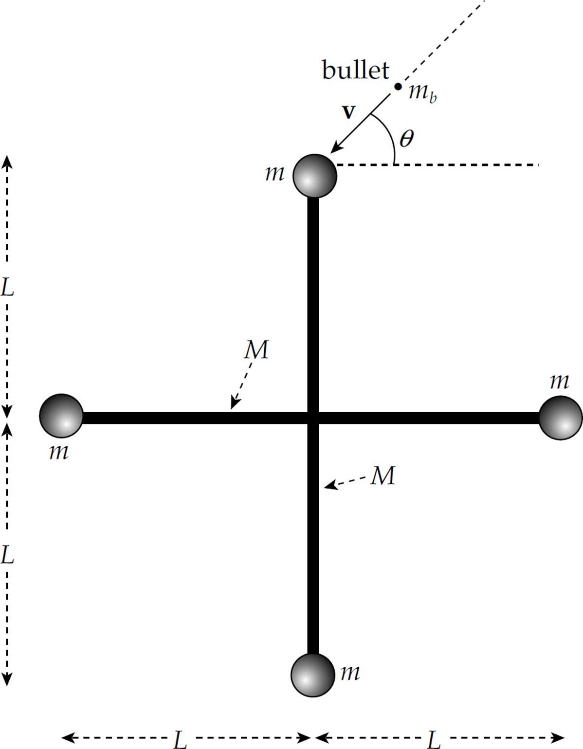
(a) Show that the moment of inertia of each slender rod about the given rotation axis, not including the clay balls, is ML2/3.
(b) Determine the angular velocity of the assembly after the bullet has become lodged in the targeted clay ball.
(c) What is the resulting linear speed of each clay ball?
(d) Determine the ratio of the final kinetic energy of the assembly to the kinetic energy of the bullet before impact.
Summary
Relating Linear and Angular Quantities
s = rθ
v = rω
atan = rα
Linear Equations and Angular Equivalents
Basic Rotation Information
- Rotational inertia is the rotational analog of inertia, essentially a measure of how difficult it is to change an object’s rotational motion.
For point masses, I = mr2
For distributed mass, I = ![]() r2 d m
r2 d m
Parallel Axis Theorem: I = Icm + md2
- Torque is a force’s ability to cause an object to rotate. The equation for torque is τ = r × F
- Newton’s Second Law for rotation:
- Rotating objects have rotational kinetic energy although the object does not necessarily translate. The equation for rotational kinetic energy is
If the object is rolling, the rotational kinetic energy is
Angular Momentum
- Angular momentum for a point particle is given by the equation L = Iω.
- Angular momentum for a rigid object is given by the equation
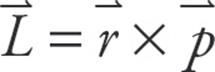 .
. - Angular momentum is conserved unless a net torque acts on the object. This is expressed by the equation Sτ = dL/dt.
- For an object to be in static equilibrium the net force and the net torque must be zero: ΣF = 0, Στ = 0.