AP Physics C Exam
Part IV
Content Review for the AP Physics C Exam
Chapter 12
Electric Potential and Capacitance
INTRODUCTION
When an object moves in a gravitational field, it usually experiences a change in kinetic energy and in gravitational potential energy due to the work done on the object by gravity. Similarly, when a charge moves in an electric field, it generally experiences a change in kinetic energy, and in electrical potential energy, due to the work done on it by the electric field. By exploring the idea of electric potential, we can simplify our calculations of work and energy changes within electric fields.
ELECTRICAL POTENTIAL ENERGY
When a charge moves in an electric field, unless its displacement is always perpendicular to the field, the electric force does work on the charge. If WE is the work done by the electric force, then the change in the charge’s electrical potential energy is defined by
ΔUE = –WE
Notice that this is the same equation that defined the change in the gravitational potential energy of an object of mass m undergoing a displacement in a gravitational field (ΔUG = –WG).
Example 1 A positive charge +q moves from position A to position B in a uniform electric field E:

What is its change in electrical potential energy?
Solution. Since the field is uniform, the electric force that the charge feels, FE = qE, is constant. Since q is positive, FE points in the same direction as E, and, as the figure shows, they point in the same direction as the displacement, r. This makes the work done by the electric field equal toWE = FEr = qEr, so the change in the electrical potential energy is
ΔUE = –qEr
Note that the change in potential energy is negative, which means that potential energy has decreased; this always happens when the field does positive work. It’s just like when you drop a rock to the ground: Gravity does positive work, and the rock loses gravitational potential energy.
Example 2 Do the previous problem, but consider the case of a negative charge, –q.
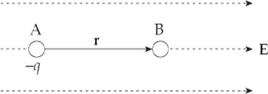
Solution. In this case, an outside agent must be pushing the charge to make it move, because the electric force naturally pushes negative charges against field lines. Therefore, we expect that the work done by the electric field is negative. The electric force, FE = (–q)E, points in the direction opposite to the displacement, so the work it does is WE = –FEr = –qEr, and the change in electrical potential energy is positive: ΔUE = –WE = –(–qEr) = qEr. Since the change in potential energy is positive, the potential energy increased; this always happens when the field does negative work. It’s like when you lift a rock off the ground: Gravity does negative work, and the rock gains gravitational potential energy.
Example 3 A positive charge +q moves from position A to position B in a uniform electric field E:
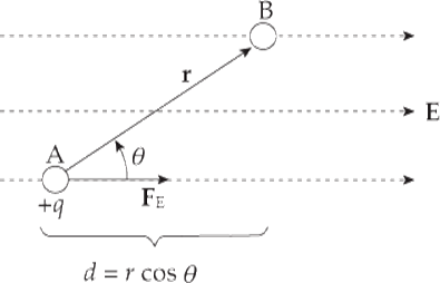
What is its change in electrical potential energy?
Solution. The electric force felt by the charge q is FE = qE and this force is parallel to E, because q is positive. In this case, because FE is not parallel to r (as it was in Example 1), we will use the more general definition of work:
WE = FE · r = FE r cos θ = qEr cos θ
But r cos θ = d, so
WE = qEd
and
ΔUE = –WE = –qEd
Because the electric force is a conservative force, which means that the work done does not depend on the path that connects the positions A and B, the work calculated above could have been figured out by considering the path from A to B composed of the segments r1 and r2:
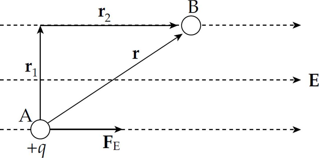
Along r1, the electric force does no work since this displacement is perpendicular to the force. Thus, the work done by the electric field as q moves from A to B is simply equal to the work it does along r2. And since the length of r2 is d = r cos θ, we have WE = FEd = qEd, just as before.
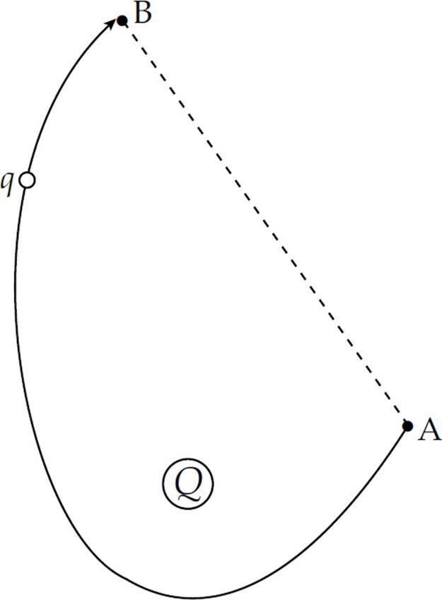
Example 4 A positive charge +q moves from position A to B in the electric field, E, created by the source charge +Q (only a portion of the electric field is drawn):
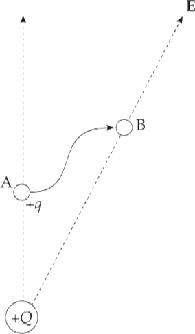
What is its change in electrical potential energy?
Solution. As you know, movement that’s perpendicular to the field lines causes the electric field to do no work. So replace the path pictured by another path, composed of r1 and r2:
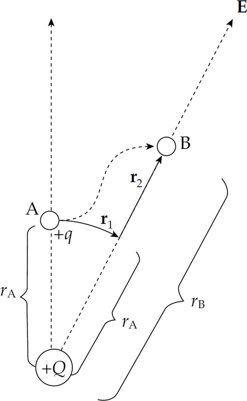
At every point along the arc r1, the electric force is radial and thus perpendicular to the displacement, so FE does no work on the charge as it moves along r1. But along radial line r2, the electric force is parallel to the displacement. The work done by the electric force is
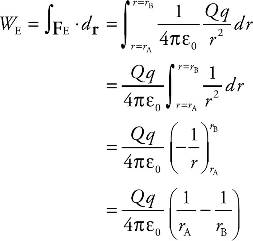
and the change in electrical potential energy is
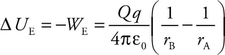
The equation above holds true regardless of the signs of Q and q. Our illustration had both Q and q positive, but this procedure can be used with any combination of signs and the result will be the same. Since the equation can be written in the form
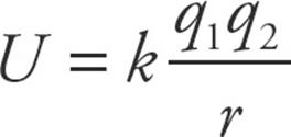
we can define the potential energy of two charges (let’s just call them q1 and q2), separated by a distance r to be
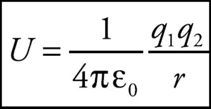
This definition says that when the charges are infinitely far apart, their potential energy is zero.
Example 5 A positive charge q1 = +2 × 10⁻⁶ C is held stationary, while a negative charge, q2 = –1 × 10⁻⁸ C, is released from rest at a distance of 10 cm from q1. Find the kinetic energy of charge q2 when it’s 1 cm from q1.
Solution. The gain in kinetic energy is equal to the loss in potential energy; you know this from Conservation of Energy. The change in electrical potential energy is
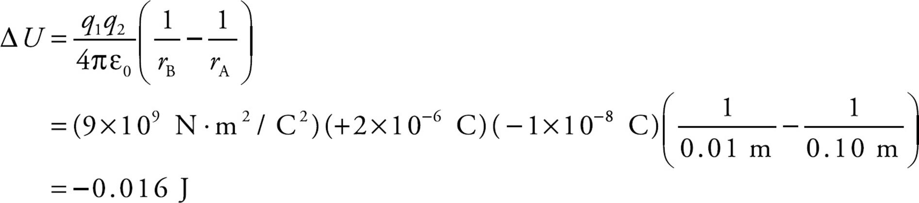
So the gain in kinetic energy is +0.016 J. Since q2 started from rest (with no kinetic energy), this is the kinetic energy of q2 when it’s 1 cm from q1.
Example 6 Two positive charges, q1 and q2, are held in the positions shown below. How much work would be required to bring (from infinity) a third positive charge, q3, and place it so that the three charges form the corners of an equilateral triangle of side length s?
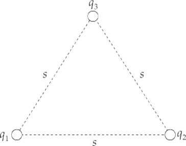
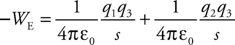
Solution. An external agent would need to do positive work, equal in magnitude to the negative work done by the electric force on q3 as it is brought into place, so let’s first compute this quantity. Let’s first compute the work done by the electric force as q3 is brought in. Since q3 is fighting against both q1’s and q2’s electric fields, the total work done on q3 by the electric force, WE, is equal to the work done on q3 by q1 (W1-3) plus the work done on q3 by q2 (W2-3). Using the equation WE = – ΔUE and the one we derived above for ΔUE, we have
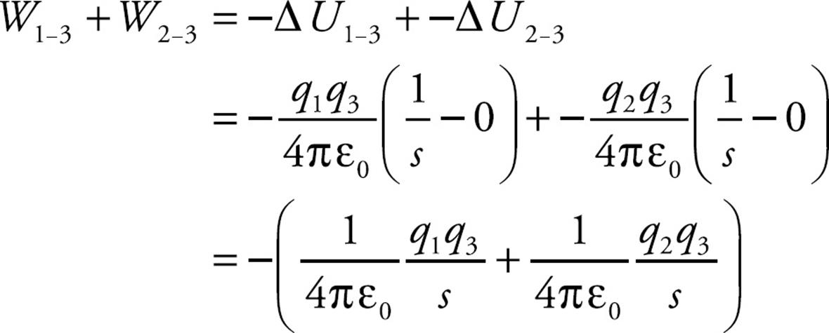
Therefore, the work that an external agent must do to bring q3 into position is
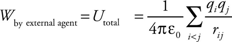
In general, the work required by an external agent to assemble a collection of point charges q1, q2, … , qn (bringing each one from infinity), such that the final fixed distance between qi and qj is rij, is equal to the total electrical potential energy of the arrangement:
Electric Potential
Let WE be the work done by the electric field on a charge q as it undergoes a displacement. If another charge, say 2q, were to undergo the same displacement, the electric force would be twice as great on this second charge, and the work done by the electric field would be twice as much, 2WE. Since the work would be twice as much in the second case, the change in electrical potential energy would be twice as great as well, but the ratio of the change in potential energy to the charge would be the same: UE/q = 2UE/2q. This ratio says something about the field and thedisplacement, but not the charge that made the move. The change in electric potential, ΔV, is defined as this ratio:
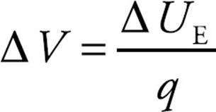
On the equation sheet for the free-response section, this information will be represented as follows:
Electric potential is electrical potential energy per unit charge; the units of electric potential are joules per coulomb. One joule per coulomb is called one volt (abbreviated V); so 1 J/C = 1 V.
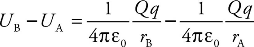
Consider the electric field that’s created by a point source charge Q. If a charge q moves from a distance rA to a distance rB from Q, then the change in the potential energy is
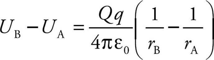
The difference in electric potential between positions A and B in the field created by Q is
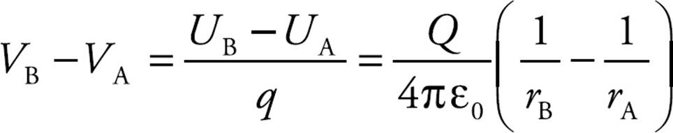
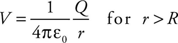
If we designate VA → 0 as rA → ∞ (an assumption that’s stated on the AP Physics Exam), then the electric potential at a distance r from Q is
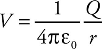
Note that the potential depends on the source charge making the field and the distance from it.
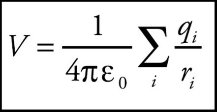
Since electric potential is a scalar, if there is more than one charge, the electric potential at a given location is the sum of the potentials due to each of the charges:
Example 7 Let Q = 2 × 10⁻⁹ C. What is the potential at a Point P that is 2 cm from Q?
Solution. Relative to V = 0 at infinity, we have
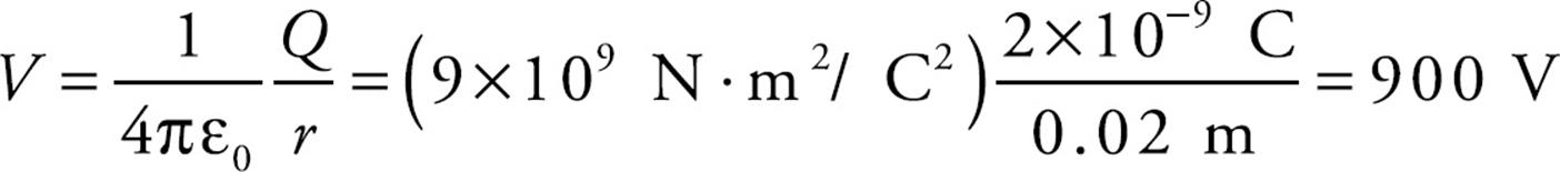
This means that the work done by the electric field on a charge of q coulombs brought from infinity to a point 2 cm from Q would be –900q joules.
Note that, like potential energy, potential is a scalar. In the preceding example, we didn’t have to specify the direction of the vector from the position of Q to the Point P, because it didn’t matter. At any point on a sphere that’s 2 cm from Q, the potential will be 900 V. These spheres around Q are called equipotential surfaces, and they’re surfaces of constant potential. Their cross sections in any plane are circles and are (therefore) perpendicular to the electric field lines. The equipotentials are always perpendicular to the electric field lines.
Example 8 How much work is done by the electric field as a charge moves along an equipotential surface?
Solution. If the charge always remains on a single equipotential, then, by definition, the potential, V, never changes. Therefore, ΔV = 0, so ΔUE = 0. Since WE = – ΔUE, the work done by the electric field is zero.
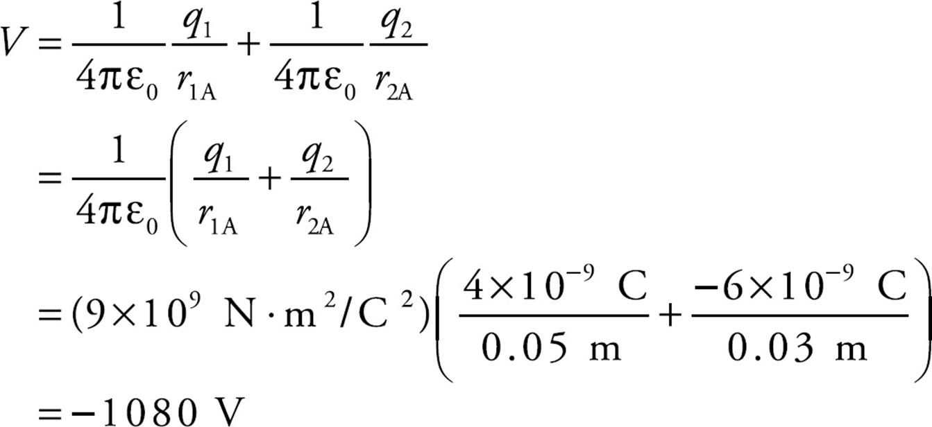
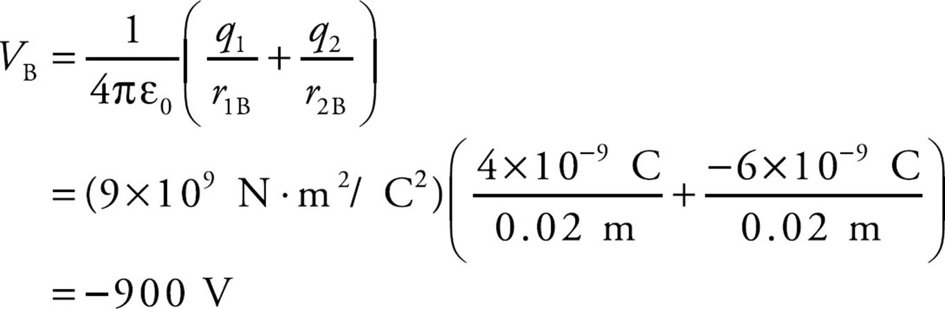
Example 9 If charges q1 = 4 × 10⁻⁹ C and q2 = –6 × 10⁻⁹ C are stationary, calculate the potential at Point A in the figure below:
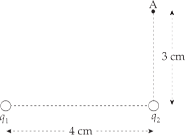
Solution. Potentials add like ordinary numbers. Therefore, the potential at A is just the sum of the potentials at A due to q1 and q2. Note that the distance from q1 to A is 5 cm.
Example 10 How much work would it take to move a charge q = +1 × 10⁻² C from Point A to Point B (the point midway between q1 and q2)?
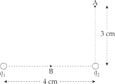
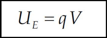
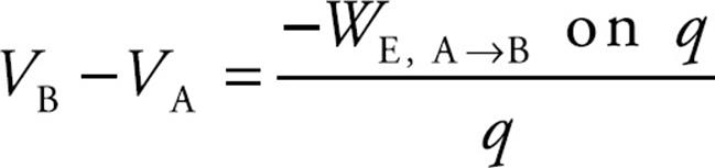
Solution. ΔUE = qΔV, so if we calculate the potential difference between Points A and B and multiply by q, we will have found the change in the electrical potential energy: ΔUA→B = qΔVA→B. Then, since the work by the electric field is –ΔU, the work required by an external agent is ΔU. In this case, the potential at Point B is
In the preceding example, we calculated the potential at Point A: VA = –1,080 V, so ΔVA→B = VB – VA = (–900 V) – (–1,080 V) = +180 V. This means that the change in electrical potential energy as q moves from A to B is
ΔUA→B = qVA→B = (+1 × 10⁻² C)(+180 V) = 1.8 J
This is the work required by an external agent to move q from A to B.
The Potential in a Uniform Field
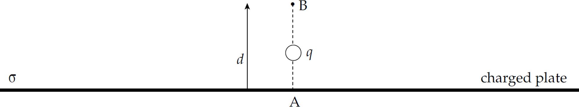
Example 11 Consider a very large, flat plate that contains a uniform surface charge density σ. At points that are not too far from the plate, the electric field is uniform and given by the equation

What is the potential at a point which is a distance d from the sheet, relative to the potential of the sheet itself?
Solution. Let A be a point on the plate and let B be a point a distance d from the sheet. Then
Since the field is constant, the force that a charge q would feel is also constant, and is equal to
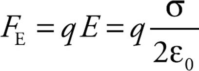
Therefore,
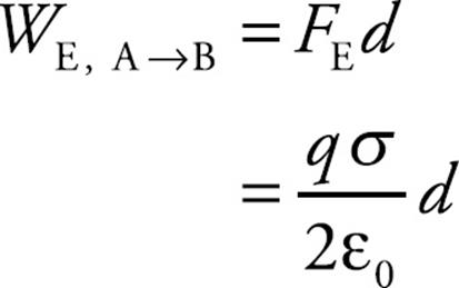
so applying the definition gives us
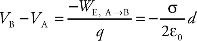
This says that for a positive s, the potential decreases linearly as we move away from the plate.
Example 12 Two large flat plates—one carrying a charge of +Q, the other –Q—are separated by a distance d. The electric field between the plates, E, is uniform. Determine the potential difference between the plates.
Solution. Imagine a positive charge q moving from the positive plate to the negative plate:
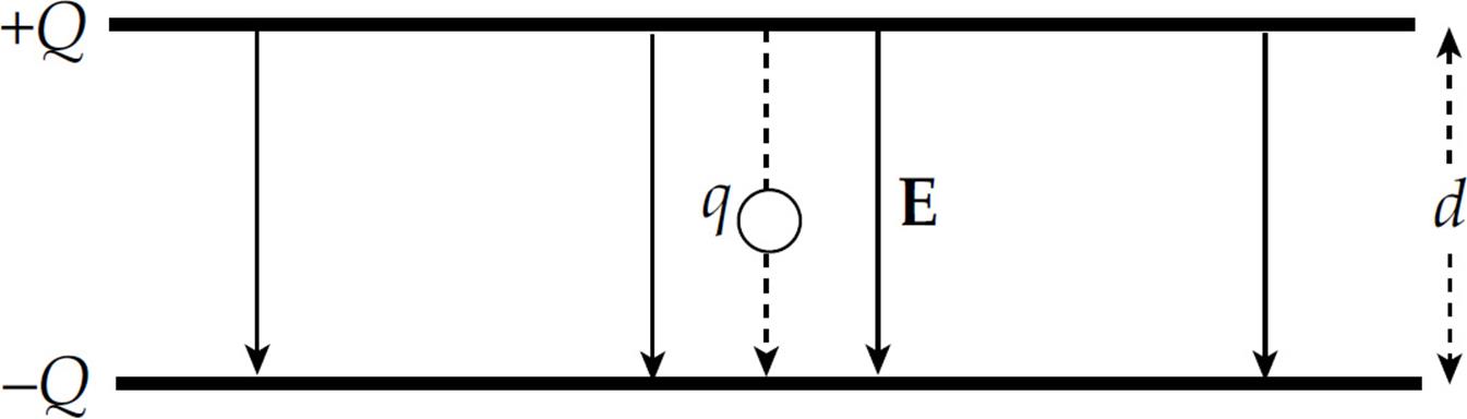
Since the work done by the electric field is
WE,+ → – = FE d = qEd
the potential difference between the plates is
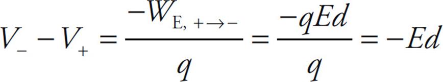
This tells us that the potential of the positive plate is greater than the potential of the negative plate, by the amount Ed. This equation can also be written as
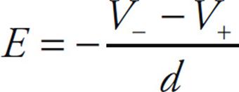
Therefore, if the potential difference and the distance between the plates are known, then the magnitude of the electric field can be determined quickly.
THE POTENTIAL OF A SPHERE
Think about a conducting spherical shell of radius R. If the shell carries an excess charge Q, we know that this excess charge will be found on the outer surface and that the electric field inside the sphere will be zero. What is the potential due to the shell? At points outside the shell, the field exists as if all of the charge of the sphere were concentrated at the center. That is, for points outside the shell, the potential is the same as it would be due to a single point charge Q:
What about at points inside the shell? Since E = 0 everywhere inside, there would be no electric force and no work done on a charge moving inside the shell. The potential is constant within the sphere. So if we moved a charge q from the surface of the spherical shell to its inside, the potential wouldn’t change. The potential everywhere inside the shell is equal to the potential on the surface, which is (1/4πε0)(Q/R). Therefore,

The same is also true for a solid conducting sphere of charge Q.
Example 13 The figure below shows two concentric, conducting, thin spherical shells. The inner shell has a radius of a and carries a charge of q. The outer shell has a radius of b and carries a charge of Q. The inner shell is supported on an insulating stand.
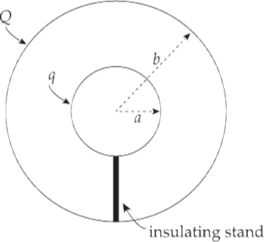
(a) What would the potential of the inner shell be if the outer shell were absent?
(b) What is the potential of the inner shell with the outer shell present?
(c) Show that the potential difference between the inner shell and the outer shell, Va – Vb, does not depend on the charge on the outer shell.
Solution.
(a) The potential on (and within) a sphere of radius a containing a charge q is given by the equation Va = (1/4πε0)(q/a).
(b) The potential inside the outer sphere (if the inner sphere were absent) is equal to (1/4πε0)(Q/b). The potential of the inner sphere if the outer sphere were absent is (1/4πε0)(q/a). So the potential of the inner sphere with the outer sphere present is the sum: (1/4πε0)(Q/b) + (1/4πε0)(q/a).
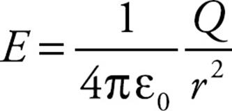
Here’s another way to arrive at this result: Outside (and on) the outer sphere, the potential is the same as if the total charge were concentrated at the center, (1/4πε0)(q + Q)/r. So at a point on the outer sphere, the potential is found by substituting b for r in this expression; this gives Vb = (1/4πε0)(q + Q)/b. Now, the electric field between the spheres is, by Gauss’s Law, simply equal to (1/4πε0)(q/r2). Therefore, the work required by an external agent to move a charge (let’s call it q0) from infinity to the inner sphere is equal to:
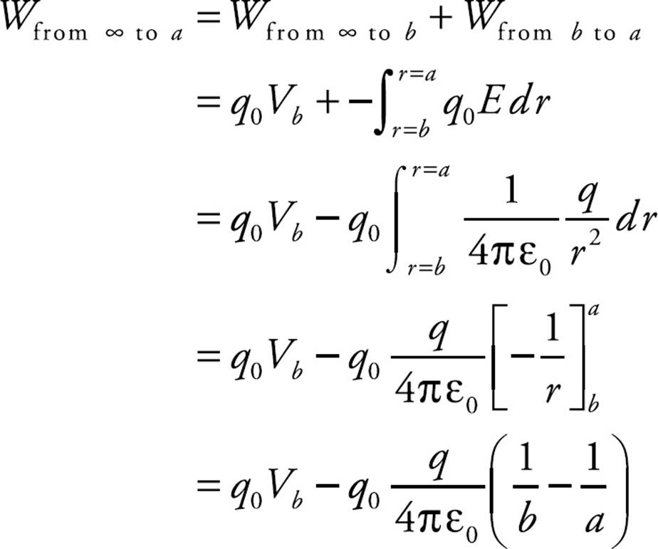
Therefore,
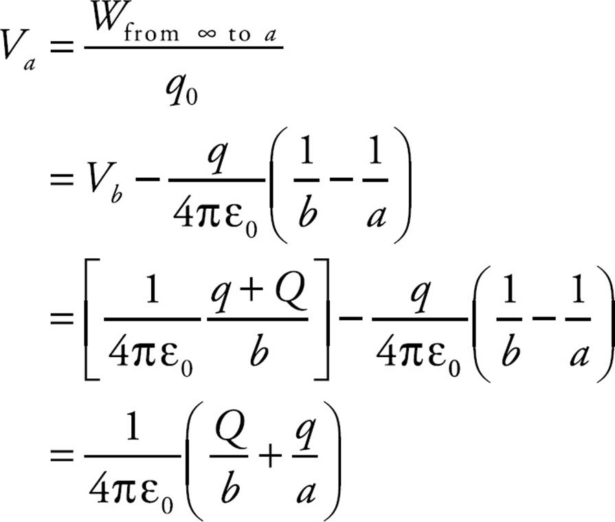
(c) At points outside the outer sphere, the two spheres behave as if all their charge was concentrated at the center. So at points outside the sphere (r > b) the potential is equal to (1/4πε0)(q + Q)/r. This must also give the potential at the surface of the outer sphere when r = b. Therefore, the potential difference between the inner sphere and the outer sphere is
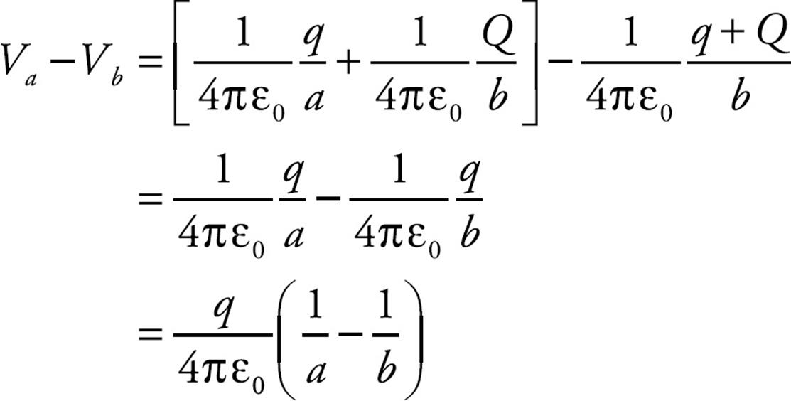
This expression does not depend on Q, which is what we were asked to show.
Example 14 A nonconducting sphere of radius R has an excess charge of Q distributed uniformly throughout its volume (that is, the volume charge density, ρ, is a constant). The electric field at a distance r < R from the center is given by the equation

What is the potential inside the sphere? That is, what is the potential at a distance r from the sphere’s center?
Solution. The potential at some distance, let’s call it r0, from the center is equal to the negative of the work done by the electric field as a charge q is brought to r0 from infinity, divided by q. (By definition, V = UE/q = –WE/q, where we take V = 0 at infinity.) So our first step (the big one) is to figure out the work done by the electric field in bringing a charge q in from infinity. At points outside the sphere, the electric field is simply (1/4πε0)(Q/r2), since the sphere behaves as if all of its charge were concentrated at its center. Once we get inside, however, the electric field is given by the formula in the question. Therefore,
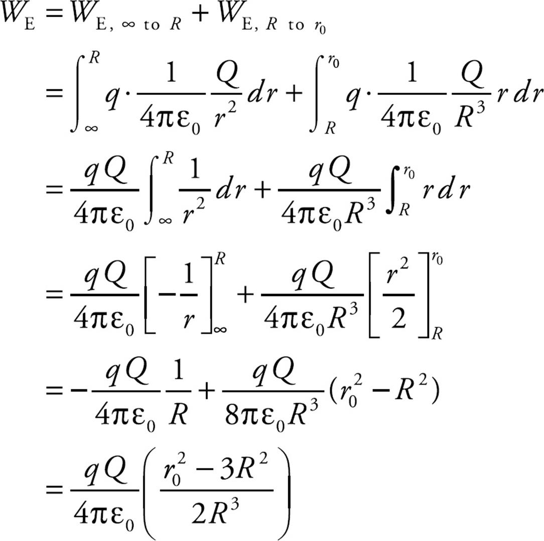
Taking the negative of this result, dividing by q, and replacing r0 with r gives us our answer:
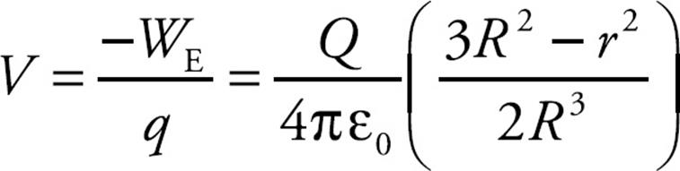
Note how this result differs from the potential of a conducting sphere. In that case, the potential was constant throughout the interior of the sphere (and was equal to the value of the potential on the surface). In this case the potential is not constant; it depends on r.
THE POTENTIAL OF A CYLINDER
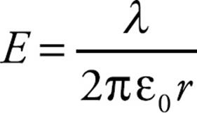
Example 15 Consider a very long conducting cylinder of radius R, which carries a uniform linear charge density λ. The electric field at a distance r, where r > R, from the center of the cylinder is given by the equation
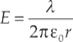
Determine a formula for the potential at a point outside the cylinder, relative to the potential on the cylinder.
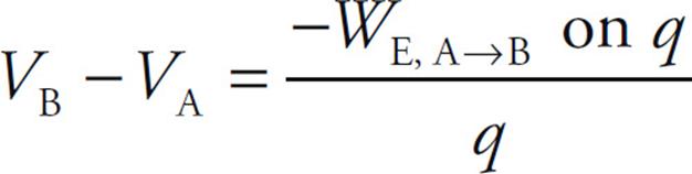
Solution. Let A be a point on the cylinder (at r = R) and let B be a point outside the cylinder (at r = r0 > R). Then, by definition,
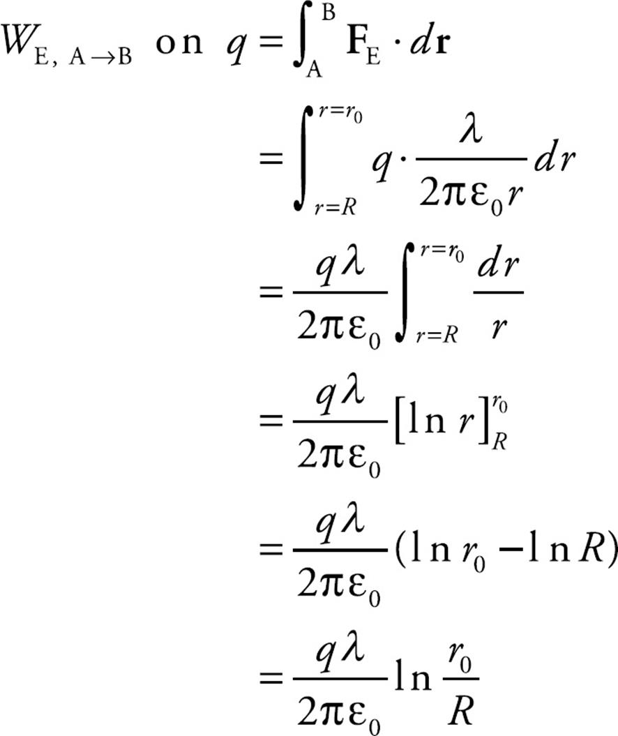
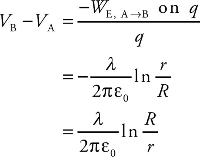
So we figure out the work done by the electric field as a charge q moves from A to B:
Replacing r0 with r, we get
Deriving the Field from the Potential
From the definition of potential,
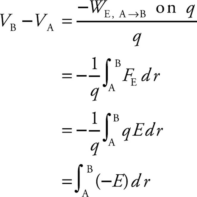
If A and B are separated by an infinitesimal distance dr, then
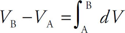
and this gives us
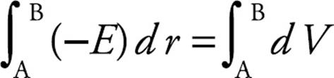
from which we can conclude that
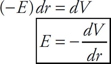
So, if we know how the potential varies as a function of r, we can determine the electric field variation with r.
Example 16 If the potential at a distance r from a source point charge Q is given by the equation V(r) = (1/4πε0)(Q/r), determine a formula for the electric field.
Solution. Using the relationship derived above,
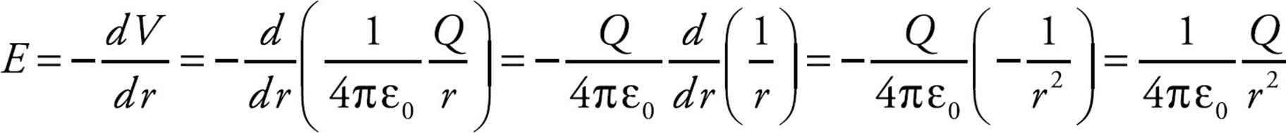
a result we know well.
Capacitance
Consider two conductors, separated by some distance, that carry equal but opposite charges, +Q and –Q. Such a pair of conductors comprise a system called a capacitor. Work must be done to create this separation of charge, and, as a result, potential energy is stored. Capacitors are basically storage devices for electrical potential energy.
The conductors may have any shape, but the most common conductors are parallel metal plates or sheets. These types of capacitors are called parallel-plate capacitors. We’ll assume that the distance d between the plates is small compared to the dimensions of the plates since, in this case, the electric field between the plates is uniform. The electric field due to one such plate, if its surface charge density is σ = Q/A, is given by the equation E = σ/(2ε0), with E pointing away from the sheet if σ is positive and toward the plate if σ is negative.
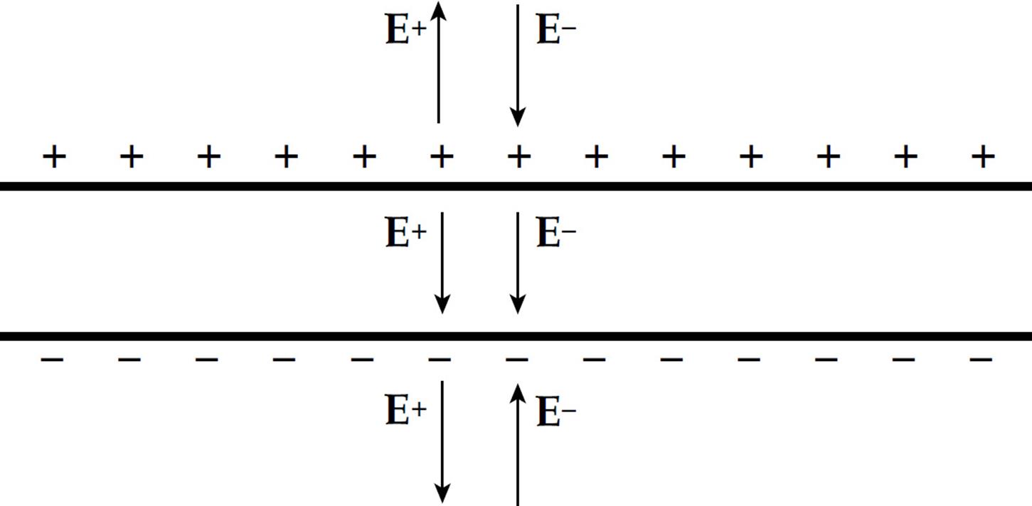
Therefore, with two plates, one with surface charge density +σ and the other, –σ, the electric fields combine to give a field that’s zero outside the plates and that has the magnitude
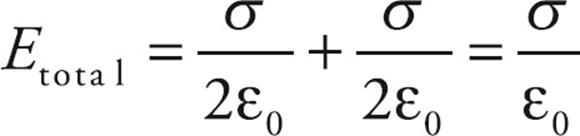
in between. In Example 12, we learned that the magnitude of the potential difference, ΔV, between the plates satisfies the relationship ΔV = Ed, so combining this with the previous equation, we get
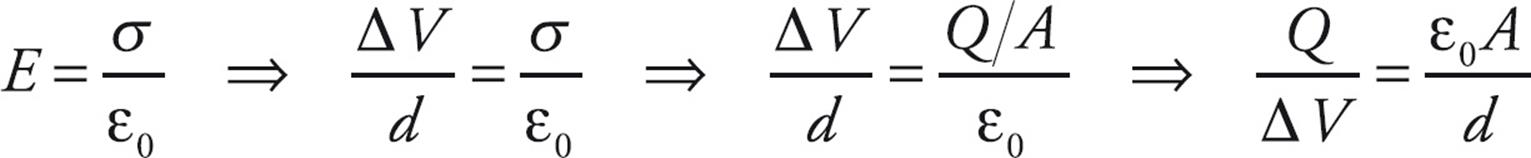
The ratio of Q to V, for any capacitor, is called its capacitance (C),
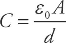
so for a parallel-plate capacitor, we get
The capacitance measures the capacity for holding charge. The greater the capacitance, the more charge can be stored on the plates at a given potential difference. The capacitance of any capacitor depends only on the size, shape, and separation of the conductors. From the definition, C =Q/ΔV, the units of C are coulombs per volt. One coulomb per volt is renamed one farad (abbreviated F): 1 C/V = 1 F.
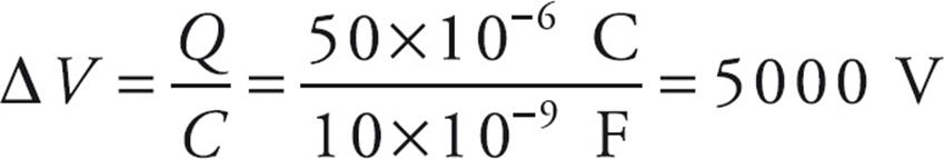
Example 17 A 10-nanofarad parallel-plate capacitor holds a charge of magnitude 50 µC on each plate.
(a) What is the potential difference between the plates?
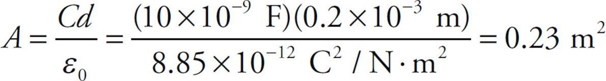
(b) If the plates are separated by a distance of 0.2 mm, what is the area of each plate?
Solution.
(a) From the definition, C = Q/ΔV, we find that
(b) From the equation C = ε0A/d, we can calculate the area, A, of each plate:
Capacitors of Other Geometries
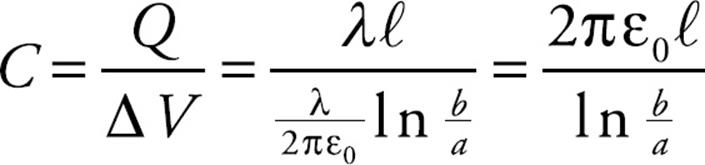
Example 18 A long cable consists of a solid conducting cylinder of radius a, which carries a linear charge density of +λ, concentric with an outer cylindrical shell of radius b, which carries a linear charge density of –λ. This is a coaxial cable. Determine the capacitance of the cable.
Solution. We first apply the definition, C = Q/ΔV. In Chapter 11, Example 13, we saw that the electric field outside of a conducting cylinder is given by the equation
Therefore, we can get the potential difference between the inner cylinder and the outer cylindrical shell by integrating the electric field. Since

we have
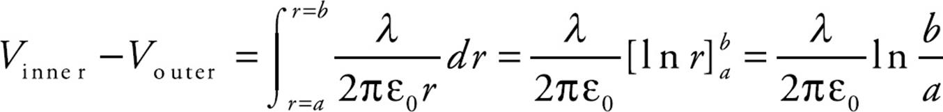
Therefore, over a length ℓ of cable, the magnitude of the charge Q on each cylinder is λℓ, so by the definition of capacitance, we get
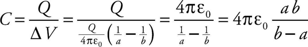
Example 19 A spherical conducting shell of radius a, which carries a charge of +Q, is concentric with an outer spherical shell of radius b, which carries a charge of –Q. What is the capacitance of this spherical capacitor?
Solution. We first apply the definition, C = Q/ΔV. We know that, in the region between the shells, the field is due to the inner shell alone:
Therefore, the potential difference between the inner sphere and the outer sphere shell is obtained by integrating the electric field as follows. Since

we have

So, by definition of capacitance, we get
The capacitance of a single, isolated conductor can also be defined; we can just think of the other conductor as being infinitely far away. In this case, if a conductor holds a charge Q at a potential of V, then its capacitance is defined as C = Q/V. For a single sphere of radius a, we determined earlier in this chapter that the potential at its surface is V = (1/4πε0)Q/a, so its capacitance is
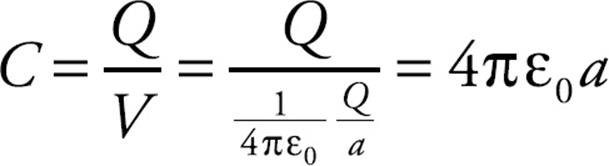
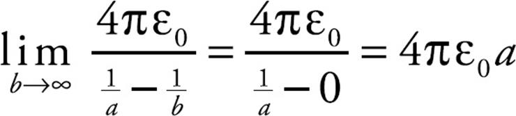
which says that C is proportional to the radius of the sphere. This makes sense; a larger sphere would have the capacity to hold more charge and should therefore have a greater capacitance. This same result for the capacitance of a single sphere can be obtained from the equation we derived above for the spherical shell capacitor simply by letting the radius b of the outer sphere go to infinity:
Combinations of Capacitors
Capacitors are often arranged in combination in electric circuits. Here we’ll look at two types of arrangements, the parallel combination and the series combination.
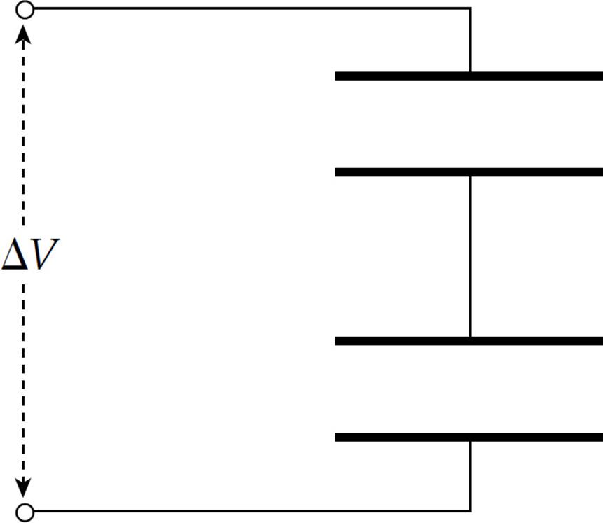
A collection of capacitors are said to be in parallel if they all share the same potential difference. The following diagram shows two capacitors wired in parallel:
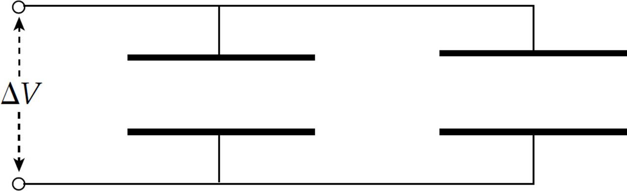
The top plates are connected by a wire and form a single equipotential; the same is true for the bottom plates. Therefore, the potential difference across one capacitor is the same as the potential difference across the other capacitor.
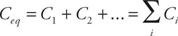
We want to find the capacitance of a single capacitor that would perform the same function as this combination. If the capacitances are C1 and C2, then the charge on the first capacitor is Q1 = C1ΔV and the charge on the second capacitor is Q2 = C2ΔV. The total charge on the combination is Q1 + Q2, so the equivalent capacitance, CP, must be
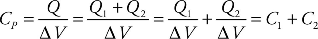
On the equation sheet for the free-response section, this information will be represented as follows:
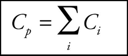
So the equivalent capacitance of a collection of capacitors in parallel is found by adding the individual capacitances.
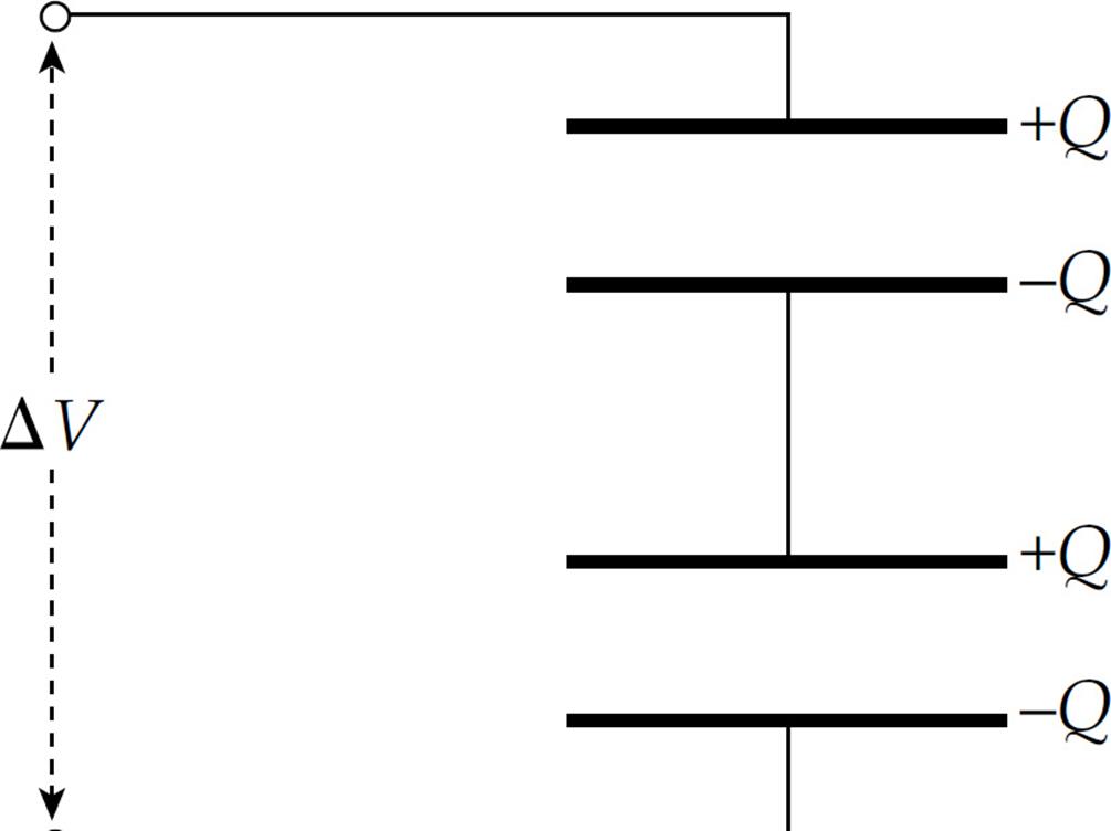
A collection of capacitors are said to be in series if they all share the same charge magnitude. The following diagram shows two capacitors wired in series:
When a potential difference is applied, as shown, negative charge will be deposited on the bottom plate of the bottom capacitor; this will push an equal amount of negative charge away from the top plate of the bottom capacitor toward the bottom plate of the top capacitor. When the system has reached equilibrium, the charges on all the plates will have the same magnitude:
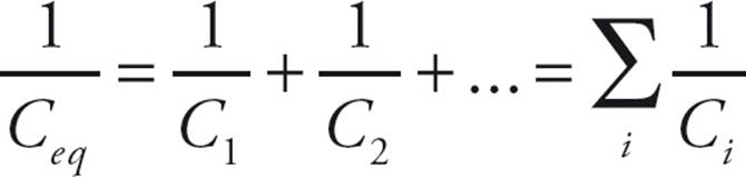
If the top and bottom capacitors have capacitances of C1 and C2, respectively, then the potential difference across the top capacitor is ΔV1 = Q/C1, and the potential difference across the bottom capacitor is ΔV2 = Q/C2. The total potential difference across the combination is ΔV1 + ΔV2, which must equal ΔV. Therefore, the equivalent capacitance, CS, must be
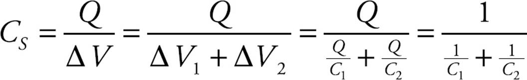
We can write this in another form:
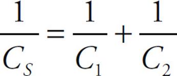
On the equation sheet for the free-response section, this information will be represented as follows:
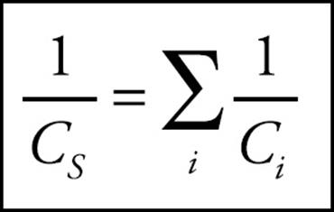
In words, the reciprocal of the capacitance of a collection of capacitors in series is found by adding the reciprocals of the individual capacitances.
Example 20 Given that C1 = 2 µF, C2 = 4 µF, an C3 = 6 µF, calculate the equivalent capacitance for the following combination:
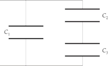
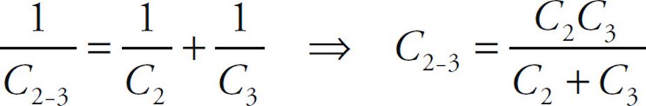
Solution. Notice that C2 and C3 are in series, and they are in parallel with C1. That is, the capacitor equivalent to the series combination of C2 and C3 (which we’ll call C2-3) is in parallel with C1. We can represent this as follows:
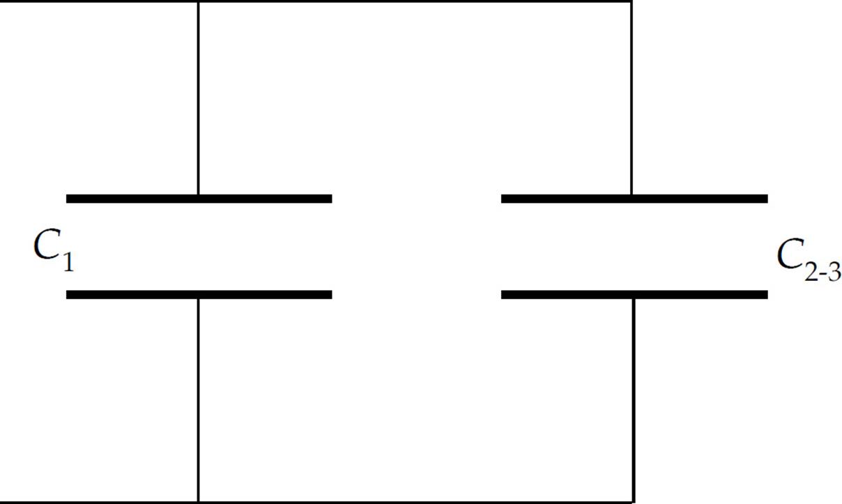
So, the first step is to find C2-3:
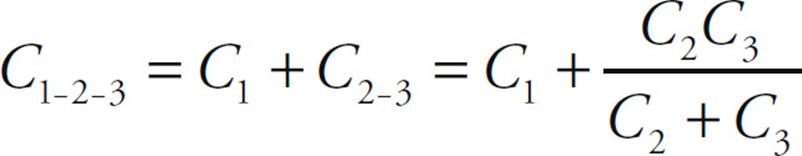
Now this is in parallel with C1, so the overall equivalent capacitance (C1-2-3) is
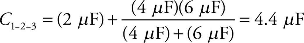
Substituting in the given numerical values, we get
The Energy Stored in a Capacitor
To figure out the electrical potential energy stored in a capacitor, imagine taking a small amount of negative charge off the positive plate and transferring it to the negative plate. This requires that positive work is done by an external agent, and this is the reason that the capacitor stores energy. If the final charge on the capacitor is Q, then we transferred an amount of charge equal to Q, fighting against the prevailing voltage at each stage. If the final voltage is ΔV, then the average voltage during the charging process is ![]() ΔV; so, because ΔUE is equal to charge times voltage, we can write ΔUE = Q ·
ΔV; so, because ΔUE is equal to charge times voltage, we can write ΔUE = Q · ![]() ΔV =
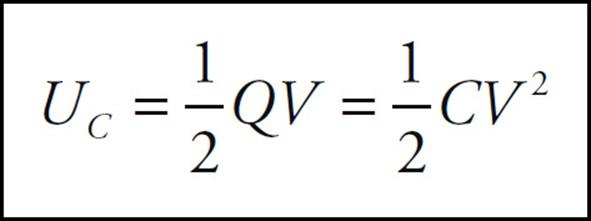
ΔV = ![]() QΔV. At the beginning of the charging process, when there was no charge on the capacitor, we had Ui = 0, so ΔUE = Uf – Ui = Uf – 0 = Uf; therefore, we have
QΔV. At the beginning of the charging process, when there was no charge on the capacitor, we had Ui = 0, so ΔUE = Uf – Ui = Uf – 0 = Uf; therefore, we have

This is the electrical potential energy stored in a capacitor. Because of the definition C = Q/ΔV, the equation for the stored potential energy can be written in two other forms:

On the equation sheet for the free-response section, this information will be represented as follows:
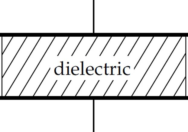
Dielectrics
One method of keeping the plates of a capacitor apart, which is necessary to maintain charge separation and store potential energy, is to insert an insulator (called a dielectric) between the plates.
A dielectric always increases the capacitance of a capacitor. Let’s see why this happens. Imagine charging a capacitor to a potential difference of V with charge +Q on one plate and –Q on the other. Now disconnect the capacitor from the charging source and insert a dielectric. What happens? Although the dielectric is not a conductor, the electric field that existed between the plates causes the molecules within the dielectric material to polarize; there is more electron density on the side of the molecule near the positive plate.
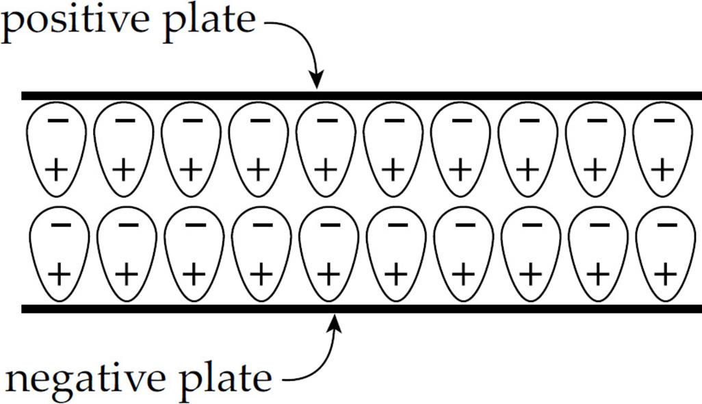
The effect of this is to form a layer of negative charge along the top surface of the dielectric and a layer of positive charge along the bottom surface; this separation of charge induces its own electric field (Ei), within the dielectric, that opposes the original electric field, E, within the capacitor:
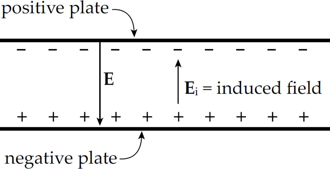
So the overall electric field has been reduced from its previous value: Etotal = E + Ei, and Etotal= E – Ei. Let’s say that the electric field has been reduced by a factor of κ (the Greek letter kappa) from its original value
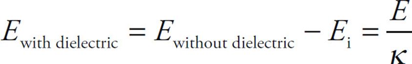
Since ΔV = Ed for a parallel-plate capacitor, we see that ΔV must have decreased by a factor of κ. But C = Q/ΔV, so if ΔV decreases by a factor of κ, then C increases by a factor of κ:
Cwith dielectric = κCwithout dielectric
The value of κ, called the dielectric constant, varies from material to material, but it’s always greater than 1.
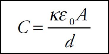
This implies that the full equation for the capacitance of a parallel-plate capacitor is:
Although the description for why the capacitance increases with the insertion of a dielectric assumed that the source that charged the capacitor was disconnected (so that Q remains constant), the same result holds if the source of potential remains connected to the capacitor. The capacitance still increases, but because ΔV must now remain constant, the equation Q = CΔV tells us that more charge will appear on the plates (because C increases).
The presence of a dielectric also limits the potential difference that can be applied across the plates. If ΔV gets too high, then E = ΔV/d gets so strong that electrons in the dielectric material can be ripped right out of their atoms and propelled toward the positive plate. This discharges the capacitor (and typically burns a hole through the dielectric). This event is called dielectric breakdown.
The capacitance formulas derived in this chapter have assumed that no dielectric was present; the permittivity constant that appears in the formulas is ε0, the permittivity of free space (vacuum). If a dielectric is present, then the permittivity increases to ε = κε0, so the occurrence of ε0 in each formula is simply replaced by ε = κε0.
Example 21 Find the charge stored and the voltage across each capacitor in the following circuit, given that ε = 180 V, C1 = 30 µF, C2 = 60 µF, and C3 = 90 µF.
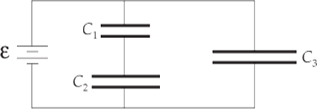
Solution. Once the charging currents stop, the voltage across C3 is equal to the voltage across the battery, so V3 = 180 V. This gives us Q3 = C3V3 = (90 µF)(180 V) = 16.2 mC. Since C1 and C2 are in series, they must store identical amounts of charge and, from the diagram, the sum of their voltages must equal the voltage of the battery. So, if we let Q be the charge on each of these two capacitors, then Q = C1V1 = C2V2, and V1 + V2 = 180 V. The equation C1V1 = C2V2 becomes (30 µF)V1 = (60 µF)V2, so V1 = 2V2. Substituting this into V1 + V2 = 180 V gives us V1 = 120 V and V2 = 60 V. The charge stored on each of these capacitors is
(30 µF)(120 V) = C1V1 = C2V2 = (60 µF)(60 V) = 3.6 mC
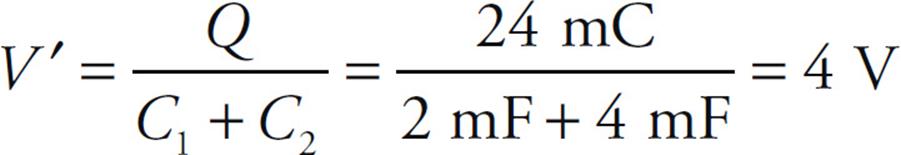
Example 22 In the diagram below, C1 = 2 mF and C2 = 4 mF. When Switch S is open, a battery (which is not shown) is connected between points a and b and charges capacitor C1 so that Vab = 12 V. The battery is then disconnected.
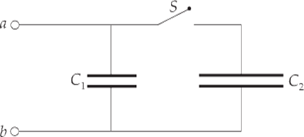
After the switch is closed, what will be the common voltage across each of the parallel capacitors (once electrostatic conditions are reestablished)?
Solution. When C1 is fully charged, the charge on (each of the plates of) C1 has the magnitude Q = C1V = (2 mF)(12 V) = 24 mC. After the switch is closed, this charge will be redistributed in such a way that the resulting voltages across the two capacitors, V′ are equal. This happens because the capacitors are in parallel. So if Q1′ is the new charge magnitude on C1 and Q2′ is the new charge magnitude on C2, we have Q1′ + Q2′, so C1V′ + C2V′ = Q, which gives us:
Example 23 The plates of a parallel-plate capacitor are separated by a distance of 2.0 mm and each has an area of 10 cm2. If a layer of polystyrene (whose dielectric constant is 2.6) is sandwiched between the plates, calculate
(a) the capacitance
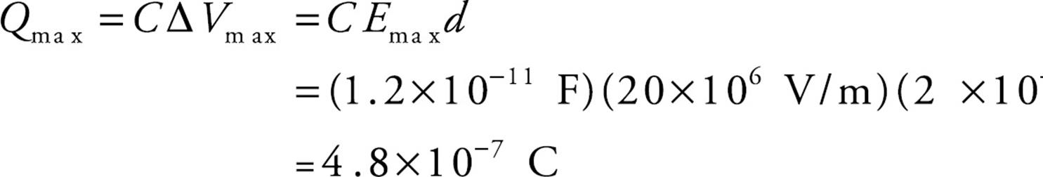
(b) the maximum amount of charge that can be placed on the plates, given that polystyrene suffers dielectric breakdown if the electric field exceeds 20 million volts per meter.
Solution.
(a) The capacitance of the parallel-plate capacitor, with a dielectric, is

Notice the units for ε0; in calculations that involve capacitance, it is usually easier to write F/m rather than C2/N·m2.
(b) First note the units for the electric field: V/m. These units follow from the equation ΔV = Ed. In the past, we’ve written the units of E as N/C. These two units are actually equivalent: 1 V/m = 1 N/C. We were asked to determine Qmax if Emax is 20 × 106 V/m and, from the equations ΔV = Ed and Q = C ΔV, we get
CHAPTER 12 REVIEW QUESTIONS
The answers and explanations can be found in Chapter 16.
Section I: Multiple Choice
1. Which of the following statements is/are true?
I. If the electric field at a certain point is zero, then the electric potential at the same point is also zero.
II. If the electric potential at a certain point is zero, then the electric field at the same point is also zero.
III. The electric potential is inversely proportional to the strength of the electric field.
(A) I only
(B) II only
(C) I and II only
(D) I and III only
(E) None are true
2. If the electric field does negative work on a negative charge as the charge undergoes a displacement from Position A to Position B within an electric field, then the electrical potential energy
(A) is negative
(B) is positive
(C) increases
(D) decreases
(E) Cannot be determined from the information given
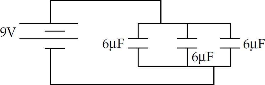
3. Three 6 µF capacitors are connected in parallel to a 9 V battery as shown above. Determine the energy stored in each capacitor.
(A) 243 J
(B) 7.29 × 10⁻⁴ J
(C) 8.10 × 10⁻⁵ J
(D) 2.43 × 10⁻⁴ J
(E) 27 J
4. Negative charges are accelerated by electric fields toward points
(A) at lower electric potential
(B) at higher electric potential
(C) where the electric field is zero
(D) where the electric field is weaker
(E) where the electric field is stronger
5. A charge q experiences a displacement within an electric field from Position A to Position B. The change in the electrical potential energy is ΔUE, and the work done by the electric field during this displacement is WE. Therefore
(A) VB – VA = WE/q
(B) VA – VB = qWE
(C) VB – VA = qWE
(D) VA – VB = ΔUE/q
(E) VB – VA = ΔUE/q
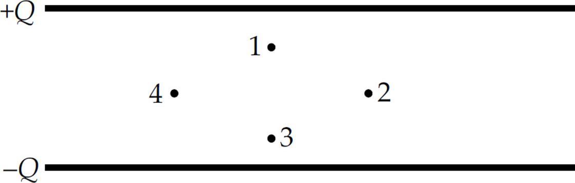
6. Which points in this uniform electric field (between the plates of the capacitor) shown above lie on the same equipotential?
(A) 1 and 2 only
(B) 1 and 3 only
(C) 2 and 4 only
(D) 3 and 4 only
(E) 1, 2, 3, and 4 all lie on the same equipotential since the electric field is uniform.
7. Two isolated and widely separated conducting spheres each carry a charge of –Q. Sphere 1 has a radius of a and Sphere 2 has a radius of 4a. If the spheres are now connected by a conducting wire, what will be the final charge on each sphere?
|
Sphere 1 |
Sphere 2 |
|
|
(A) |
–Q |
–Q |
|
(B) |
–2Q/3 |
–4Q/3 |
|
(C) |
–4Q/3 |
–2Q/3 |
|
(D) |
–2Q/5 |
–8Q/5 |
|
(E) |
–8Q/5 |
–2Q/5 |
8. A parallel-plate capacitor is charged to a potential difference of ΔV; this results in a charge of +Q on one plate and a charge of –Q on the other. The capacitor is disconnected from the charging source, and a dielectric is then inserted. What happens to the potential difference and the stored electrical potential energy?
(A) The potential difference decreases, and the stored electrical potential energy decreases.
(B) The potential difference decreases, and the stored electrical potential energy increases.
(C) The potential difference increases, and the stored electrical potential energy decreases.
(D) The potential difference increases, and the stored electrical potential energy increases.
(E) The potential difference decreases, and the stored electrical potential energy remains unchanged.
9. How much work would the electric field (created by the stationary charge Q) perform as a charge q is moved from Point A to B along the curved path shown? VA = 200 V, VB = 100 V, q = –0.05 C, length of line segment AB = 10 cm, length of curved path = 20 cm.
(A) –10 J
(B) –5 J
(C) +5 J
(D) +10 J
(E) +2 J
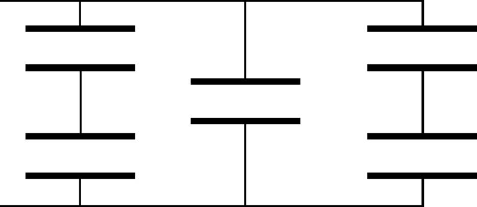
10. If each of the capacitors in the array shown above is C, what is the capacitance of the entire combination?
(A) C/2
(B) 2C/3
(C) 5C/6
(D) 2C
(E) 5C/3
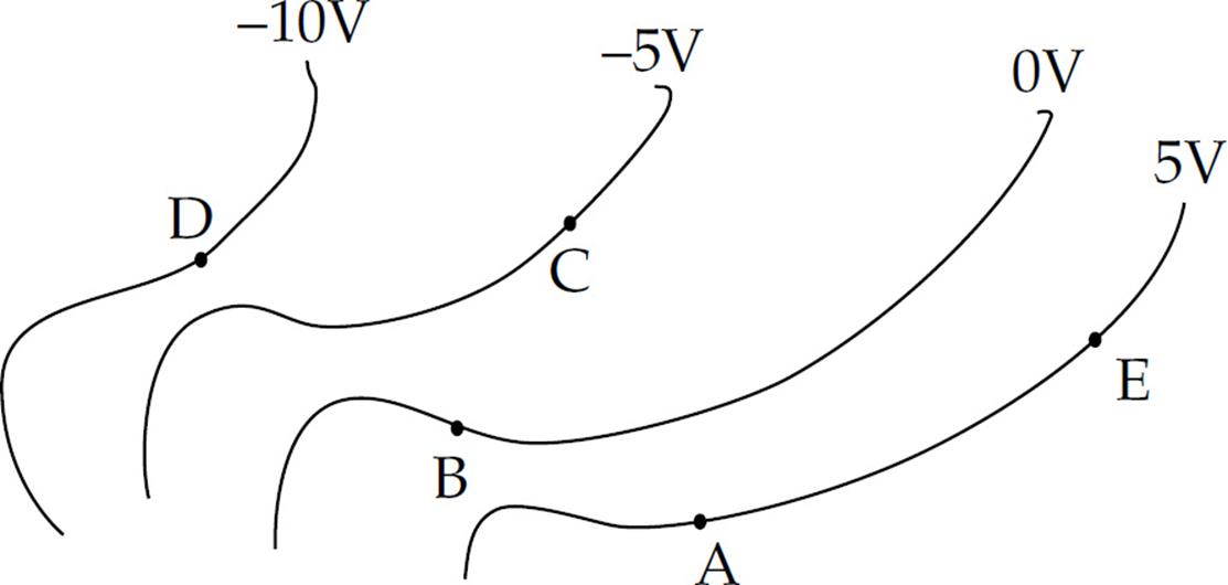
11. The diagram above shows equipotential lines produced by a charge distribution. A, B, C, D, and E are points in the plane. An electron begins at point A. The electron is then moved to point E and then from point E to point C. Which of the following correctly describes the work done by the field for each part of the movement?
|
Movement |
Movement |
|
|
(A) |
Negative |
Positive |
|
(B) |
Zero |
Positive |
|
(C) |
Zero |
Negative |
|
(D) |
Negative |
Zero |
|
(E) |
Positive |
Positive |
Section II: Free Response
1. In the figure shown, all four charges are situated at the corners of a square with sides s.
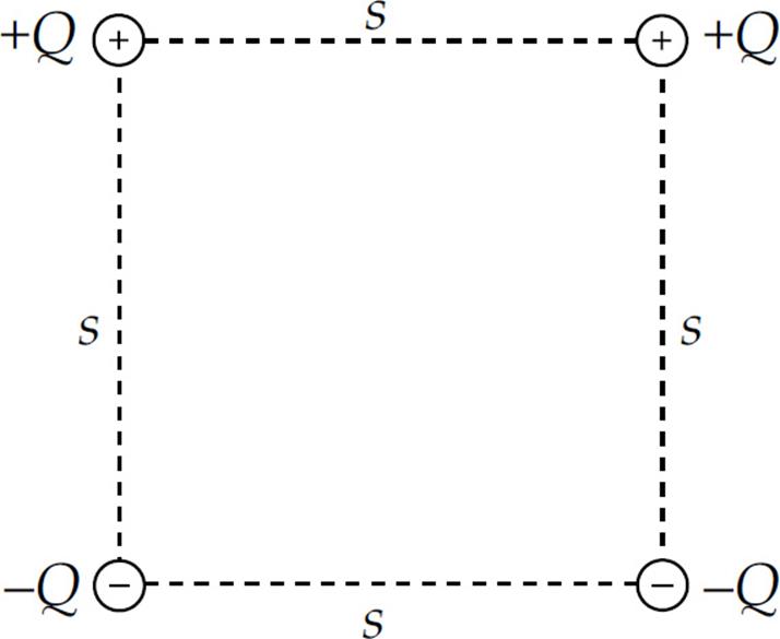
(a) What is the total electrical potential energy of this array of fixed charges?
(b) What is the electric field at the center of the square?
(c) What is the electric potential at the center of the square?
(d) Sketch (on the diagram) the portion of the equipotential surface that lies in the plane of the figure and passes through the center of the square.
(e) How much work would the electric field perform on a charge q as it moved from the midpoint of the right side of the square to the midpoint of the top of the square?
2. The figure below shows a parallel-plate capacitor. Each rectangular plate has length L and width w, and the plates are separated by a distance d.
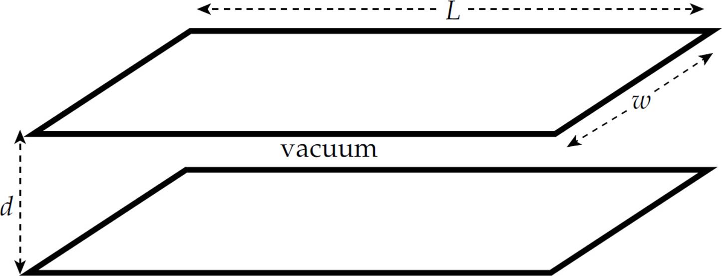
(a) Determine the capacitance.
An electron (mass m, charge –e) is shot horizontally into the empty space between the plates, midway between them, with an initial velocity of magnitude v0. The electron just barely misses hitting the end of the top plate as it exits. (Ignore gravity.)
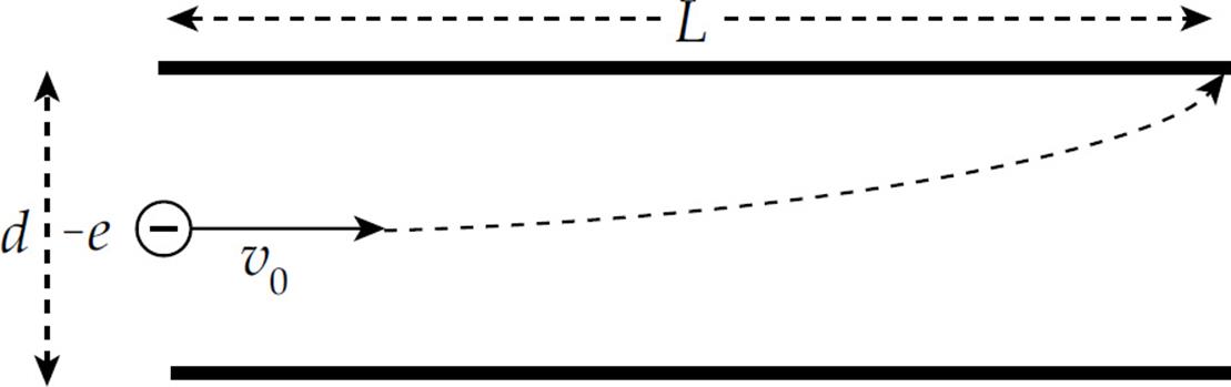
(b) In the diagram, sketch the electric field vector at the position of the electron when it has traveled a horizontal distance of L/2.
(c) In the diagram, sketch the electric force vector on the electron at the same position as in part (b).
(d) Determine the strength of the electric field between the plates. Write your answer in terms of L, d, m, e, and v0.
(e) Determine the charge on the top plate.
(f) How much potential energy is stored in the capacitor?
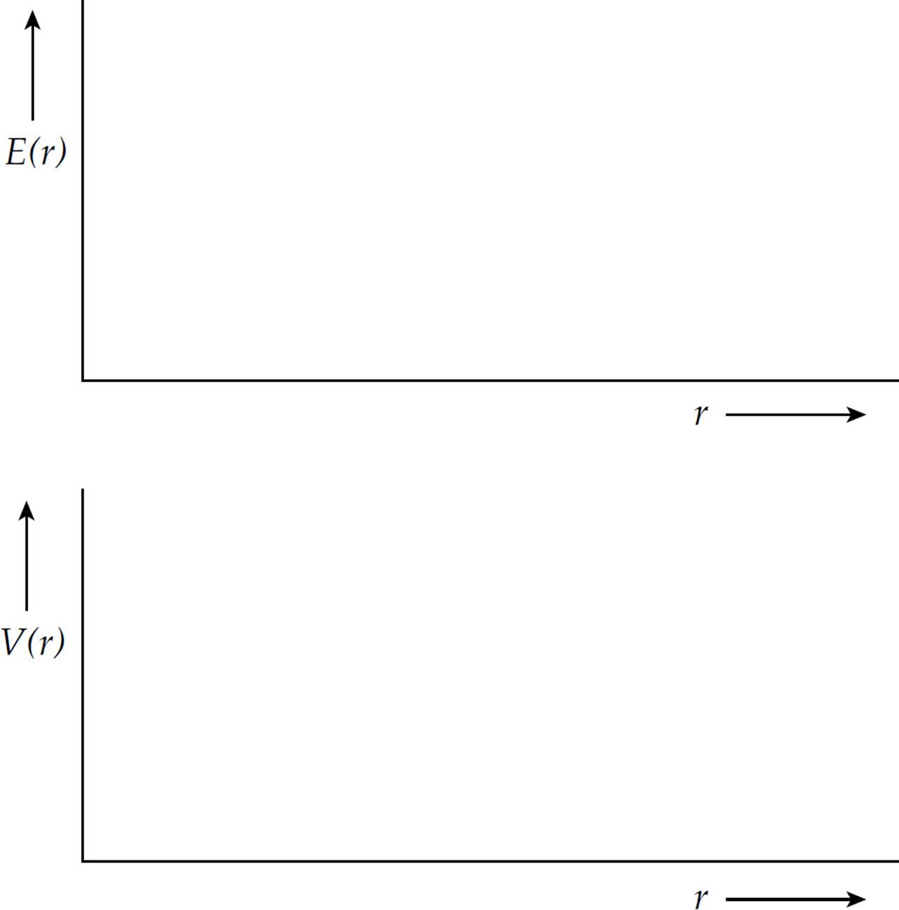
3. A solid conducting sphere of radius a carries an excess charge f Q.
(a) Determine the electric field magnitude, E(r), as a function of r, the distance from the sphere’s center.
(b) Determine the potential, V(r), as a function of r. Take the zero of potential at r = ∞.
(c) On the diagrams below, sketch E(r) and V(r). (Cover at least the range 0 < r < 2a.)
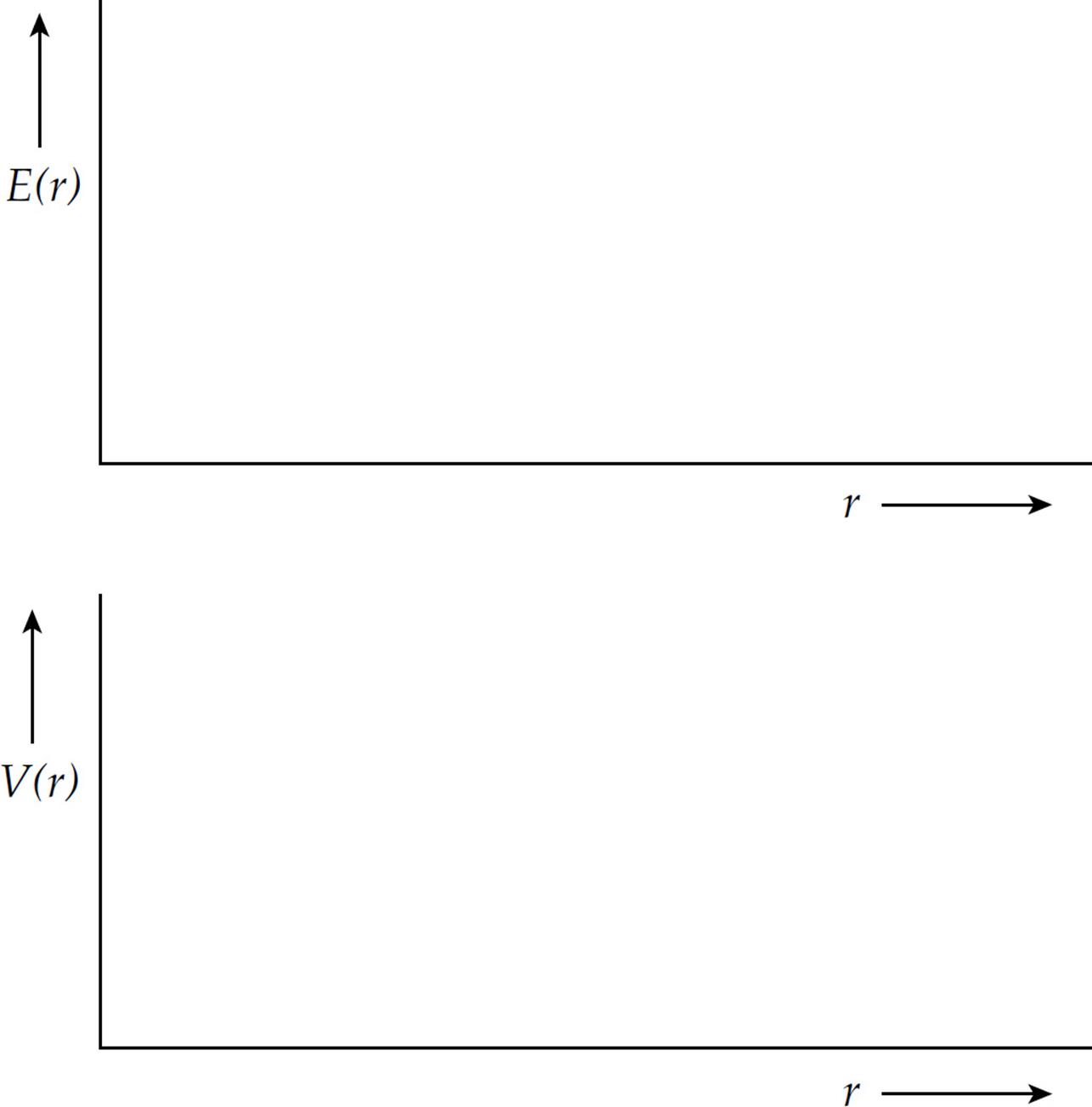
4. A solid, nonconducting sphere of radius a has a volume charge density given by the equation ρ(r) = ρ0(r/a)3, where r is the distance from the sphere’s center.
(a) Determine the electric field magnitude, E(r), as a function of r.
(b) Determine the potential, V(r), as a function of r. Take the zero of potential at r = ∞.
(c) On the diagrams below, sketch E(r) and V(r). Be sure to indicate on the vertical axis in each plot the value at r = a.
Summary
Electric Potential
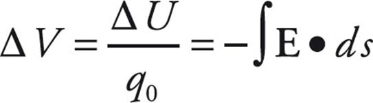
- When a positive test charge q0 moves through an electric field, its electric potential energy changes. The change in electric potential energy is:
 . Note that this is a dot product between the electric field and the path, ds.
 - When the electric field is uniform then ΔU = –q0Ed, where d is the distance along the electric field that the charge moved.
- The electric potential is the electric potential energy divided by the test charge. Therefore
 . This can also be rearranged as
 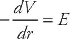 . Either one of these equations can be used to relate the electric potential to the electric field strength. The units of electric potential are volts (V), and it is often called voltage.
 - When the electric field is uniform, the electric potential is given by the strength of the electric field and the distance the object moves along the electric field: ΔV = –Ed
- The electric potential due to a point charge, Q, is
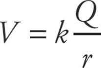 .
. - The electric potential energy between a pair of charges is
Capacitance
- Capacitors store electric potential energy by separating opposite charges. Capacitance is measured by the ratio of the charge stored to the potential difference across the capacitor:
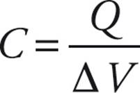 . The units are farads (F).
 - The capacitance of a parallel plate capacitor is
- When capacitors are in parallel the equivalent capacitance is the sum of the capacitances:
- When capacitors are added in series the reciprocal of the equivalent capacitance is the sum of the reciprocals of each capacitance:
- The energy stored in a capacitor is
- Dielectrics are used in capacitors to induce an opposing electric field that decreases the total electric field between the plates. This decreases the electric potential and therefore increases the capacitance.