AP Physics C Exam
Part IV
Content Review for the AP Physics C Exam
Chapter 13
Direct Current Circuits
INTRODUCTION
In the previous chapter, when we studied electrostatic fields, we learned that within a conductor an electrostatic field cannot be sustained; the source charges move to the surface and the conductor forms a single equipotential. We will now look at conductors within which an electric field can be sustained because a power source maintains a potential difference across the conductor, allowing charges to continually move through it. This ordered motion of charge through a conductor is called electric current.
ELECTRIC CURRENT
Picture a piece of metal wire. Within the metal, electrons are zooming around at speeds of about a million m/s in random directions, colliding with other electrons and positive ions in the lattice. This constitutes charge in motion, but it doesn’t constitute net movement of charge, because the electrons move randomly. If there’s no net motion of charge, there’s no current. However, if we were to create a potential difference between the ends of the wire, meaning if we set up an electric field, the electrons would experience an electric force, and they would start to drift through the wire.
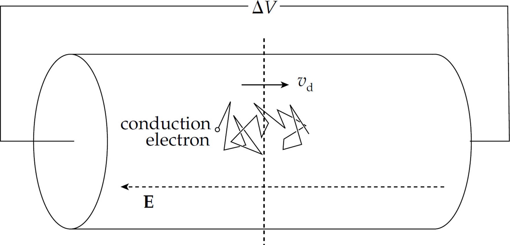
This is current. Although the electric field would travel through the wire at nearly the speed of light, the electrons themselves would still have to make their way through a crowd of atoms and other free electrons, so their drift speed, vd, would be relatively slow: on the order of a millimeter per second.
To measure the current, we have to measure how much charge crosses a plane per unit time. If an amount of charge of magnitude ΔQ crosses an imaginary plane in a time interval Δt, then the current is
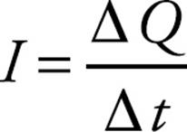
If the amount of current is changing during the time interval Δt, then the equation above gives the average current. We can define the instantaneous current as
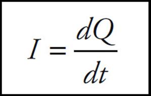
Because current is charge per unit time, it’s expressed in coulombs per second. One coulomb per second is an ampere (abbreviated as A), or amp. So 1 C/s = 1 A.
Although the charge carriers that constitute the current within a metal are electrons, the direction of the current is taken to be the direction in which positive charge carriers would move. So, if the conduction electrons drift to the right, we’d say the current points toward the left.
Resistance
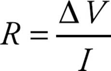
Let’s say we had a copper wire and a glass fiber that had the same length and cross-sectional area, and that we hooked up the ends of the metal wire to a source of potential difference and measured the resulting current. If we were to do the same thing with the glass fiber, the current would probably be too small to measure, but why? Well, the glass provided more resistance to the flow of charge. If the potential difference is ΔV and the current is I, then the resistance is
On the equation sheet for the free-response section, this information will be represented as follows:
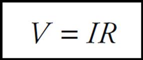
This is known as Ohm’s Law. Ohm’s Law is not a “law” in the sense that all circuit elements follow it. Only certain conductors do, and these devices are called “ohmic.” Devices for which the ratio ΔV/I is not constant are called “non-ohmic.” A light bulb is an example of a non-ohmic device. Notice that if the current is large, the resistance is low, and if the current is small, then resistance is high. The Δ in the equation above is often omitted, but you should always assume that, in this context, V = ΔV = potential difference, also called voltage.
Because resistance is voltage divided by current, it is expressed in volts per amp. One volt per amp is one ohm (Ω, omega). So, 1 V/A = 1 Ω.
Resistivity
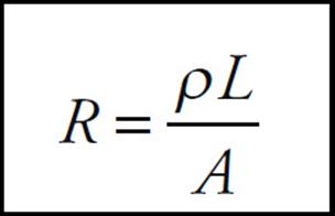
The resistance of an object depends on two things: the material it’s made of and its shape. For example, again think of the copper wire and glass fiber of the same length and area. They have the same shape, but their resistances are different because they’re made of different materials. Glass has a much greater intrinsic resistance than copper does; it has a greater resistivity. Each material has its own characteristic resistivity, and resistance depends on how the material is shaped. For a wire of length L and cross-sectional area A made of a material with resistivity ρ, resistance is given by:
The resistivity of copper is around 10–8 Ω·m, while the resistivity of glass is much greater, around 1012 Ω·m.
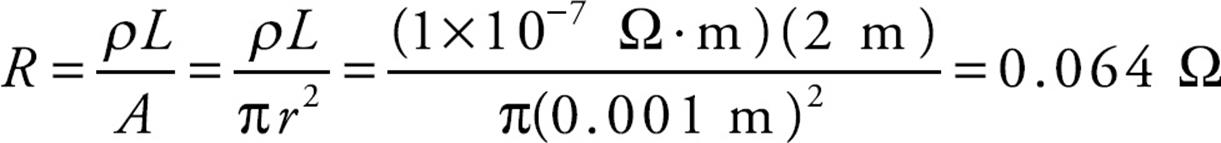
Example 1 A cylindrical wire of radius 1 mm and length 2 m is made of platinum (resistivity = 1 × 10⁻⁷ Ω·m). If a voltage of 9 V is applied between the ends of the wire, what will be the resulting current?
Solution. First, the resistance of the wire is given by the equation
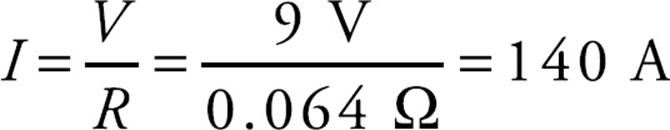
Then, from I = V/R, we get
ELECTRIC CIRCUITS
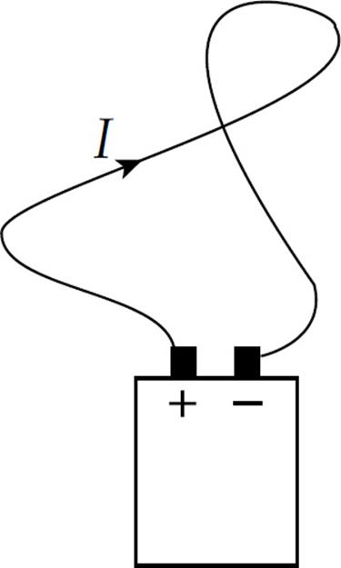
An electric current is maintained when the terminals of a voltage source (a battery, for example) are connected by a conducting pathway in what’s called a circuit. If the current always travels in the same direction through the pathway, it’s called a direct current.
The job of the voltage source is to provide a potential difference called an emf, or electromotive force, which drives the flow of charge. The emf isn’t really a force; it’s the work done per unit charge and it’s measured in volts.
To try to imagine what’s happening in a circuit in which a steady-state current is maintained, let’s follow one of the charge carriers that’s drifting through the pathway. (Remember we’re pretending that the charge carriers are positive.) The charge is introduced by the positive terminal of the battery and enters the wire, where it’s pushed by the electric field. It encounters resistance, bumping into the relatively stationary atoms that make up the metal’s lattice and setting them into greater motion. So the electrical potential energy that the charge had when it left the battery is turning into heat. By the time the charge reaches the negative terminal, all of its original electrical potential energy is lost. In order to keep the current going, the voltage source must do positive work on the charge, forcing it to move from the negative terminal toward the positive terminal. The charge is now ready to make another journey around the circuit.
Energy and Power
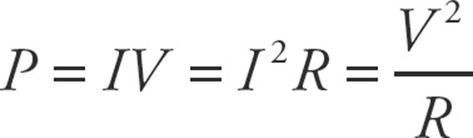
When a carrier of positive charge q drops by an amount V in potential, it loses potential energy in the amount qV. If this happens in time t, then the rate at which this energy is transformed is equal to (qV)/t = (q/t)V. But q/t is equal to the current, I, so the rate at which electrical energy is transferred is given by the equation
![]()
This equation works for the power delivered by a battery to the circuit as well as for resistors. The power dissipated in a resistor, as electrical potential energy is turned into heat, is given by P = IV, but, because of the relationship V = IR, we can express this in two other ways:
P = IV = I(IR) = I2R
or
Resistors become hot when current passes through them; the thermal energy generated is called joule heat.
Circuit Analysis
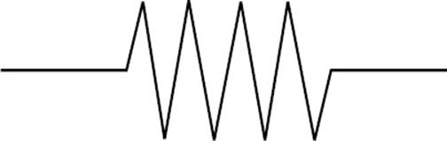
We will now develop a way of specifying the current, voltage, and power associated which each element in a circuit. Our circuits will contain three basic elements: batteries, resistors, and connecting wires. As we’ve seen, the resistance of an ordinary metal wire is negligible; resistance is provided by devices that control the current: resistors. All the resistance of the system is concentrated in the resistors, which are symbolized in a circuit diagram by this symbol:
Batteries are denoted by the symbol:
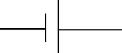
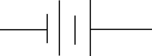
where the longer line represents the positive (higher potential) terminal, and the shorter line is the negative (lower potential) terminal. Sometimes a battery is denoted by more than one pair of such lines:
Here’s a simple circuit diagram:
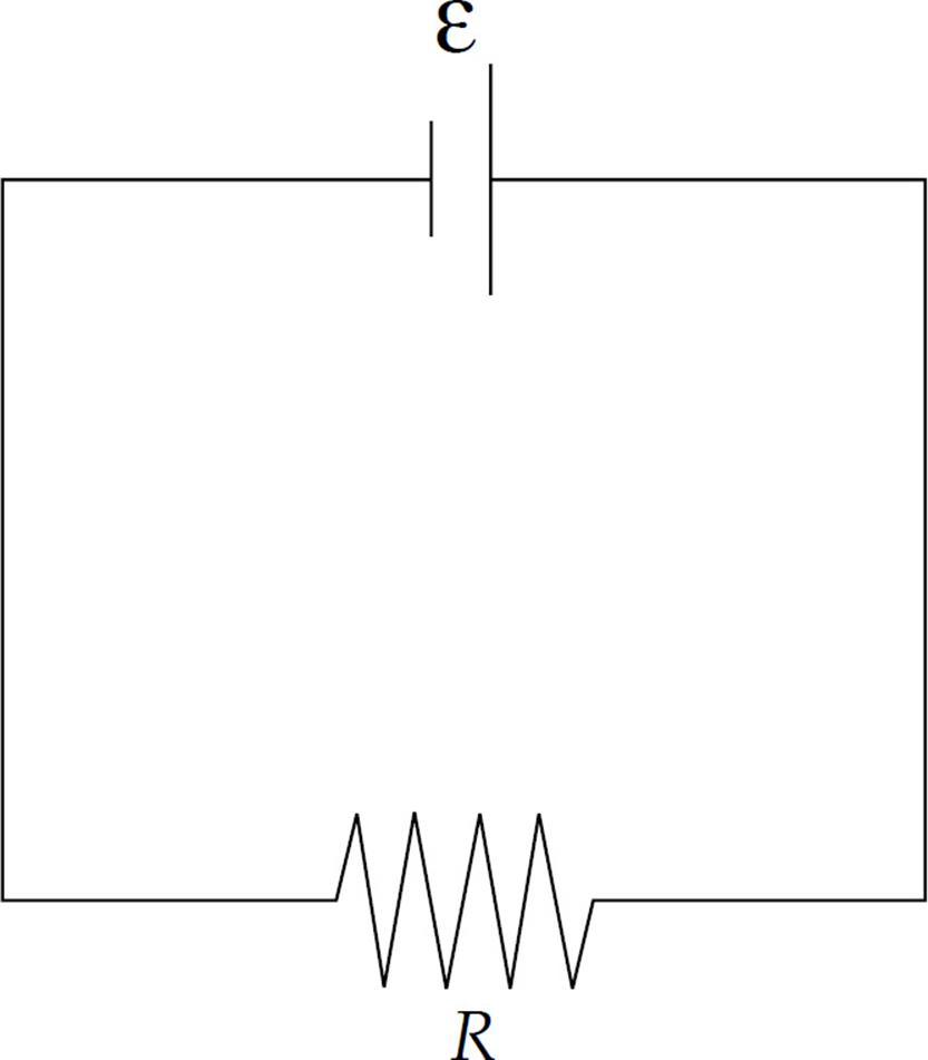
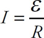
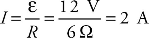
The emf (ε) of the battery is indicated, as is the resistance (R) of the resistor. Determining the current in this case is straightforward, because there’s only one resistor. The equation V = IR, with given by ε, gives us
Combinations of Resistors
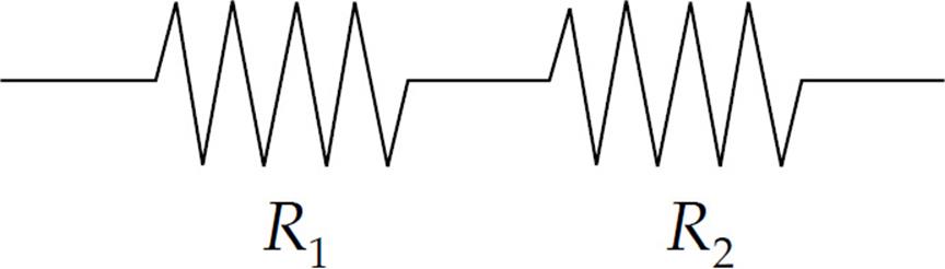
Two common ways of combining resistors within a circuit is to place them either in series (one after the other),
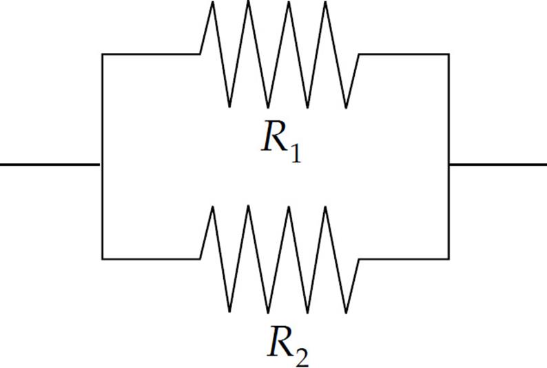
or in parallel (that is, side-by-side):
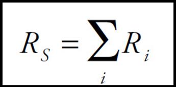
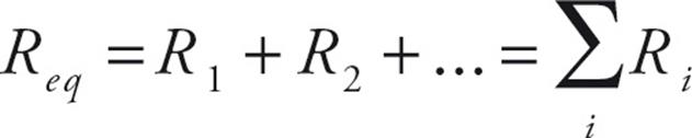
In order to simplify the circuit, our goal is to find the equivalent resistance of combinations. Resistors are said to be in series if they all share the same current and if the total voltage drop across them is equal to the sum of the individual voltage drops.
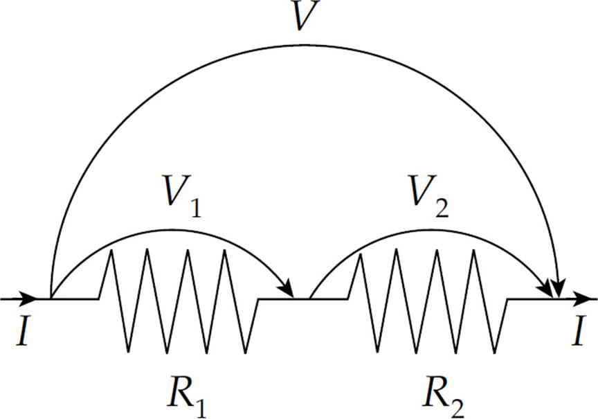
In this case, then, if V denotes the voltage drop across the combination, we have
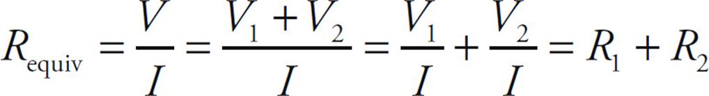
This idea can be applied to any number of resistors in series (not just two):
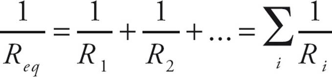
Resistors are said to be in parallel if they all share the same voltage drop, and the total current entering the combination is split among the resistors. Imagine that a current I enters the combination. It splits; some of the current, I1, would go through R1, and the remainder, I2, would go through R2.
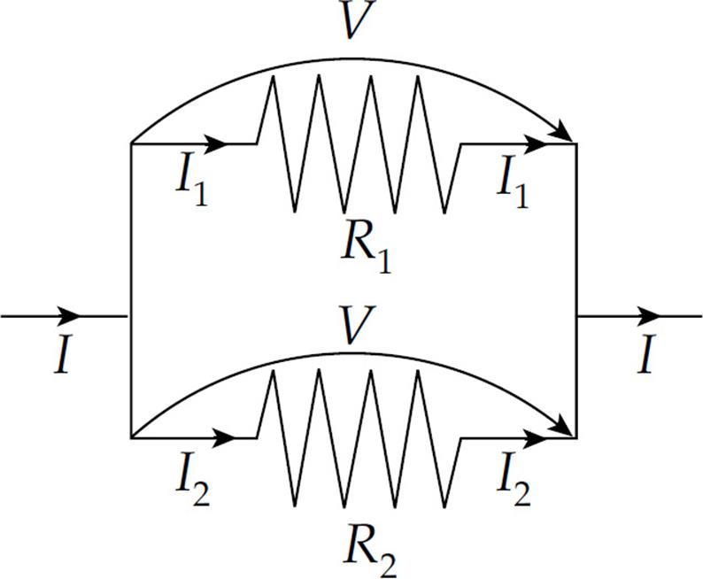
So if V is the voltage drop across the combination, we have
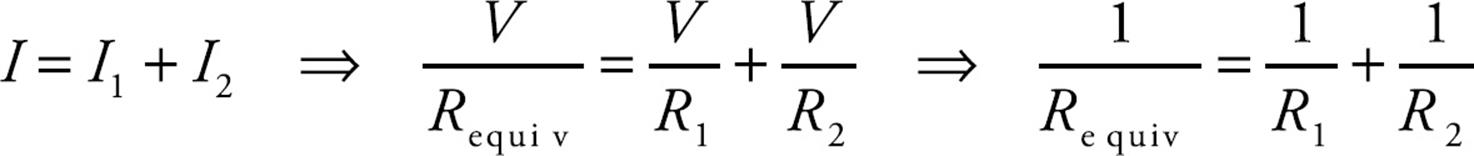
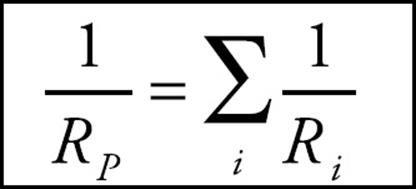
This idea can be applied to any number of resistors in parallel (not just two): The reciprocal of the equivalent resistance for resistors in parallel is equal to the sum of the reciprocals of the individual resistances:
Example 2 Calculate the equivalent resistance for the following circuit:
Solution. First find the equivalent resistance of the two parallel resistors:
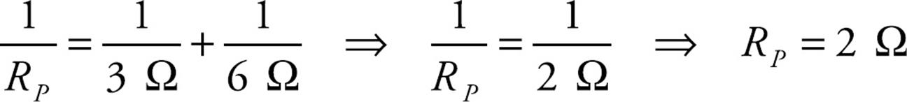
This resistance is in series with the 4 Ω resistor, so the overall equivalent resistance in the circuit is R = 4 Ω + 2 Ω = 6 Ω.
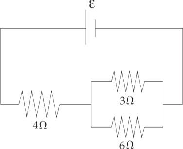
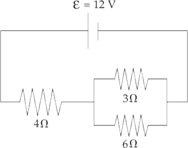
Example 3 Determine the current through each resistor, the voltage drop across each resistor, and the power given off (dissipated) as heat in each resistor of this circuit:
Solution. You might want to redraw the circuit each time we replace a combination of resistors by its equivalent resistance. From our work in the preceding example, we have
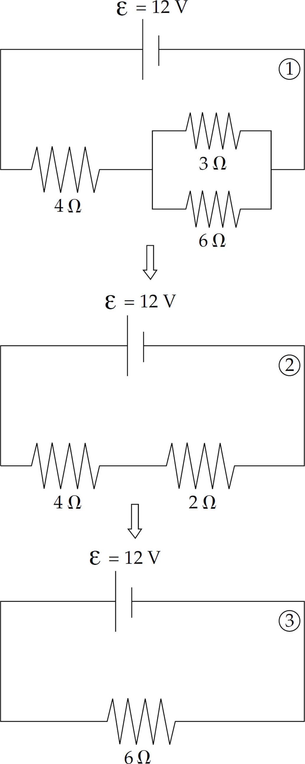
From diagram ![]() , which has just one resistor, we can figure out the current:
, which has just one resistor, we can figure out the current:
Now we can work our way back to the original circuit (Diagram ![]() ). In going from
). In going from ![]() to
to ![]() , we are going back to a series combination, and what do resistors in series share? That’s right, the same current. So, we take the current, I = 2 A, back to Diagram
, we are going back to a series combination, and what do resistors in series share? That’s right, the same current. So, we take the current, I = 2 A, back to Diagram ![]() . The current through each resistor in Diagram
. The current through each resistor in Diagram ![]() is 2 A.
is 2 A.
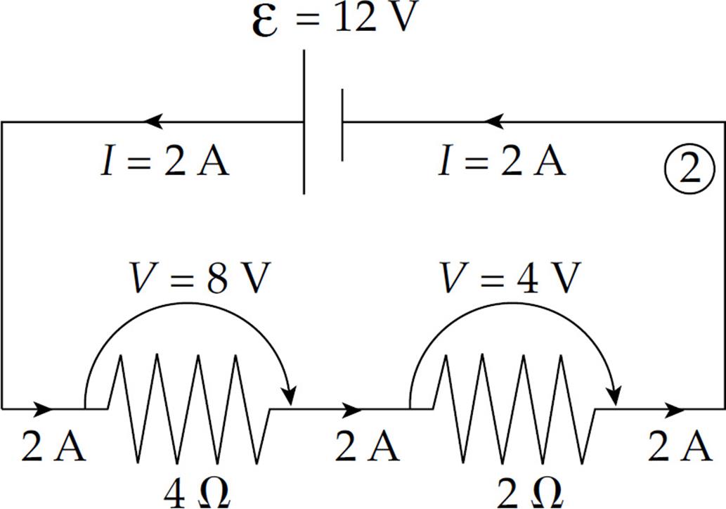
Since we know the current through each resistor, we can figure out the voltage drop across each resistor using the equation V = IR. The voltage drop across the 4 Ω resistor is (2 A)(4 Ω) = 8 V, and the voltage drop across the 2 Ω resistor is (2 A)(2 Ω) = 4 V. Notice that the total voltage drop across the two resistors is 8 V + 4 V = 12 V, which matches the emf of the battery, which is to be expected.
Now for the last step; going from diagram ![]() back to diagram
back to diagram ![]() . Nothing needs to be done with the 4 Ω resistor; nothing about it changes in going from diagram
. Nothing needs to be done with the 4 Ω resistor; nothing about it changes in going from diagram ![]() to
to ![]() , but the 2 Ω resistor in diagram
, but the 2 Ω resistor in diagram ![]() goes back to the parallel combination. And what do resistors in parallel share? The same voltage drop. So we take the voltage drop, V = 4 V, back to diagram
goes back to the parallel combination. And what do resistors in parallel share? The same voltage drop. So we take the voltage drop, V = 4 V, back to diagram ![]() . The voltage drop across each of the two parallel resistors in diagram
. The voltage drop across each of the two parallel resistors in diagram ![]() is 4 V.
is 4 V.
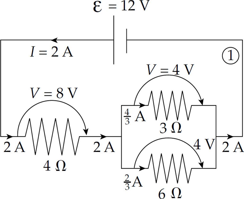
Since we know the voltage drop across each resistor, we can figure out the current through each resistor by using the equation I = V/R. The current through the 3 Ω resistor is (4 V)/(3 Ω) = ![]() A, and the current through the 6 Ω resistor is (4 V)/(6 Ω) =
A, and the current through the 6 Ω resistor is (4 V)/(6 Ω) = ![]() A. Note that the current entering the parallel combination (2 A) equals the total current passing through the individual resistors (
A. Note that the current entering the parallel combination (2 A) equals the total current passing through the individual resistors (![]() A +
A + ![]() A). Again this was expected.
A). Again this was expected.
Finally, we will calculate the power dissipated as heat by each resistor. We can use any of the equivalent formulas: P = IV, P = I2R, or P = V2/R.
For the 4 Ω resistor: P = IV = (2 A)(8 V) = 16 W
For the 3 Ω resistor: P = IV = (![]() A)(4 V) =
A)(4 V) = ![]() W
W
For the 6 Ω resistor: P = IV = (![]() A)(4 V) =
A)(4 V) = ![]() W
W
So, the resistors are dissipating a total of

If the resistors are dissipating a total of 24 J every second, then they must be provided with that much power. This is easy to check: P = IV = (2 A)(12 V) = 24 W.
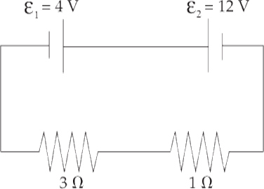
Example 4 For the following circuit,
(a) In which direction will current flow and why?
(b) What’s the overall emf?
(c) What’s the current in the circuit?
(d) At what rate is energy consumed by, and provided to, this circuit?
Solution.
(a) The battery whose emf is ε1 wants to send current clockwise, while the battery whose emf is ε2 wants to send current counterclockwise. Since ε2 > ε1, the battery whose emf is ε2 is the more powerful battery, so the current will flow counterclockwise.
(b) Charges forced through ε1 will lose, rather than gain, 4 V of potential, so the overall emf of this circuit is ε2 – ε1 = 8 V.
(c) Since the total resistance is 3 Ω + 1 Ω = 4 Ω, the current will be I = (8 V)/(4 Ω) = 2 A.
(d) ε2 will provide energy at a rate of P2 = IV2 = (2 A)(12 V) = 24 W, while ε1 will absorb at a rate of P1 = IV1 = (2 A)(4 V) = 8 W. Finally, energy will be dissipated in these resistors at a rate of I2R1 + I2R2 = (2 A)2(3 Ω) + (2 A)2(1 Ω) = 16 W. Once again, energy is conserved; the power delivered (24 W) equals the power taken (8 W + 16 W = 24 W).
Example 5 All real batteries contain internal resistance, r. Determine the current in the following circuit when the switch S is closed.
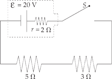
Solution. Before the switch is closed, there is no complete conducting pathway from the positive terminal of the battery to the negative terminal, so no current flows through the resistors. However, once the switch is closed, the resistance of the circuit is 2 Ω + 3 Ω + 5 Ω = 10 Ω, so the current in the circuit is I = (20 V)/(10 Ω) = 2 A. Often the battery and its internal resistance are enclosed in a dashed box in the shape of a battery.
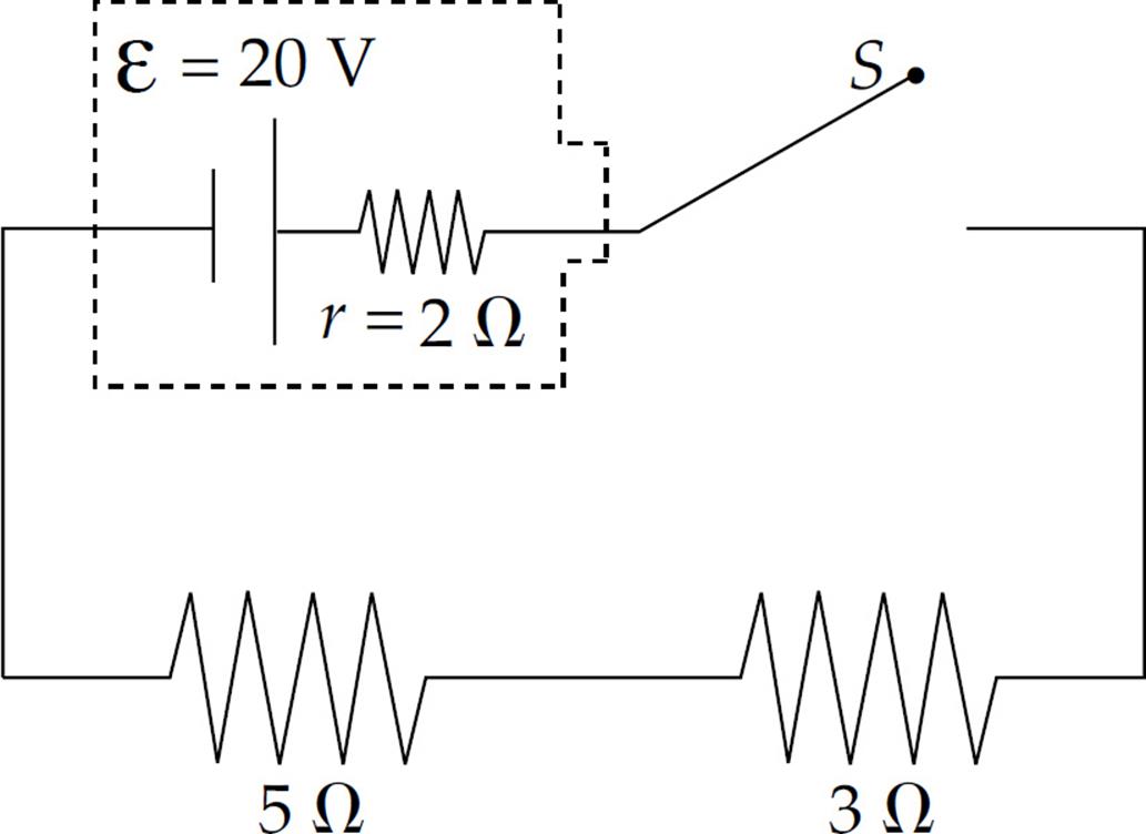
In this case, a distinction can be made between the emf of the battery and the actual voltage it provides once the current has begun. Since I = 2 A, the voltage drop across the internal resistance is Ir = (2 A)(2 Ω) = 4 V, so the effective voltage provided by the battery to the rest of the circuit—called the terminal voltage—is lower than the ideal emf. It is V = ε – Ir = 20n – 4 V = 16 V.
Example 6 A student has three 30 Ω resistors and an ideal 90 V battery. (A battery is ideal if it has a negligible internal resistance.) Compare the current drawn from—and the power supplied by—the battery when the resistors are arranged in parallel versus in series.
Solution. Resistors in series always provide an equivalent resistance that’s greater than any of the individual resistances, and resistors in parallel always provide an equivalent resistance that’s smaller than their individual resistances. So, hooking up the resistors in parallel will create the smallest resistance and draw the greatest total current:
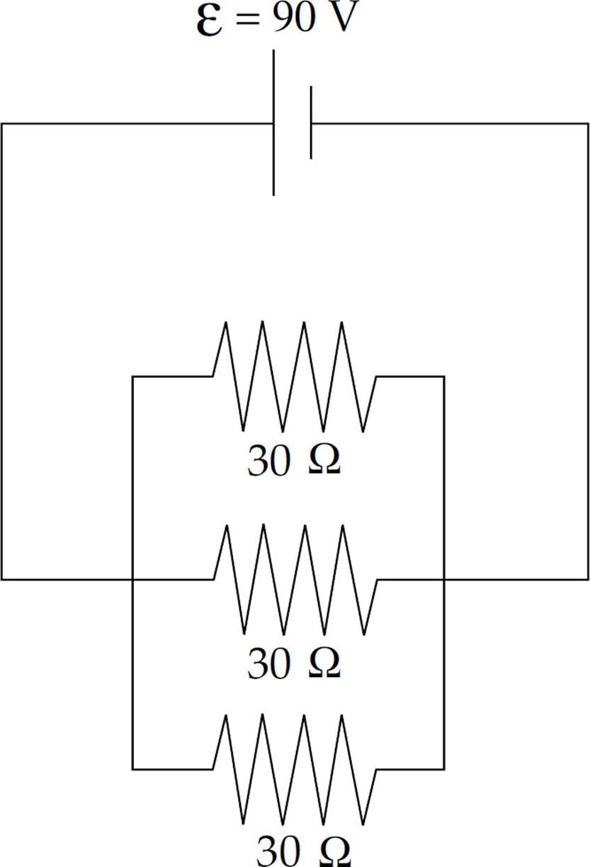
In this case, the equivalent resistance is

and the total current is I = ε/RP = (90 V)/(10 Ω) = 9 A. (You could verify that 3 A of current would flow in each of the three branches of the combination.) The power supplied by the battery will be P = IV = (9 A)(90 V) = 810 W.
If the resistors are in series, the equivalent resistance is RS = 30 Ω + 30 Ω + 30 Ω = 90 Ω, and the current drawn is only I = ε/RS = (90 V)/(90 Ω) = 1 A. The power supplied by the battery in this case is just P = IV = (1 A)(90 V) = 90 W.
Example 7 A voltmeter is a device that’s used to measure the voltage between two points in a circuit. An ammeter is used to measure current. Determine the readings on the voltmeter (denoted ![]() ) and the ammeter (denoted
) and the ammeter (denoted ![]() ) in the circuit below.
) in the circuit below.
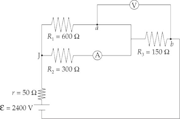
Solution. We consider the ammeter to be ideal; this means it has negligible resistance, so it doesn’t alter the current that it’s trying to measure. Similarly, we consider the voltmeter to have an extremely high resistance, so it draws negligible current away from the circuit.
Our first goal is to find the equivalent resistance in the circuit. The 600 Ω and 300 Ω resistors are in parallel; they’re equivalent to a single 200 Ω resistor. This is in series with the battery’s internal resistance, r, and R3. The overall equivalent resistance is therefore R = 50 Ω + 200 Ω + 150 Ω = 400 Ω, so the current supplied by the battery is I = ε/R (2400 V)/(400 Ω) = 6 A. At the junction marked J, this current splits. Since R1 is twice R2, half as much current will flow through R1 as through R2; the current through R1 is I1 = 2 A, and the current through R2 is I2 = 4 A. The voltage drop across each of these resistors is I1R1 = I2R2 = 1200 V (matching voltages verify the values of currents I1 and I2). Since the ammeter is in the branch that contains R2, it will read I2 = 4 A.
The voltmeter will read the voltage drop across R3, which is V3 = IR3 = (6 A) (150 Ω) = 900 V. So the potential at point b is 900 V lower than at point a. Ammeters measure current, and since current is the same in series, ammeters should be connected in series in a circuit. By the same logic, voltmeters measure potential, which is the same in parallel. So we connect them in parallel.
Example 8 The diagram below shows a point a at potential V = 20 V connected by a combination of resistors to a point (denoted G) that is grounded. The ground is considered to be at potential zero. If the potential at point a is maintained at 20 V, what is the current throughR3?
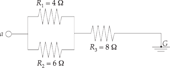
Solution. R1 and R2 are in parallel; their equivalent resistance is RP, where
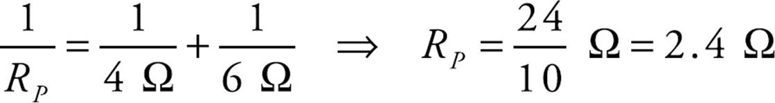
RP is in series with R3, so the equivalent resistance is:
R = RP + R3 = (2.4Ω) + (8Ω) = 10.4Ω
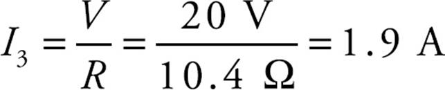
and the current that flows through R3 is
Kirchhoff’s Rules
When the resistors in a circuit cannot be classified as either in series or in parallel, we need another method for analyzing the circuit. The rules of Gustav Kirchhoff (pronounced “Keer-koff”) can be applied to any circuit:
The Loop Rule. The sum of the potential differences (positive and negative) that traverse any closed loop in a circuit must be zero.
The Junction Rule. The total current that enters a junction must equal the total current that leaves the junction. (This is also known as the Node Rule.)
The Loop Rule just says that, starting at any point, by the time we get back to that same point by following any closed loop, we have to be back to the same potential. Therefore, the total drop in potential must equal the total rise in potential. Put another way, the Loop Rule says that all the decreases in electrical potential energy (for example, caused by resistors in the direction of the current) must be balanced by all the increases in electrical potential energy (for example, caused by a source of emf from the negative to positive terminal). So the Loop Rule is basically a statement of the Law of Conservation of Energy.
Similarly, the Junction Rule simply says that the charge (per unit time) that goes into a junction must equal the charge (per unit time) that comes out. This is basically a re-statement of the Law of Conservation of Charge.
In practice, the Junction Rule is straightforward to apply. The most important things to remember about the Loop Rule can be summarized as follows:
- When going across a resistor in the same direction as the current, the potential drops by IR.
- When going across a resistor in the opposite direction from the current, the potential increases by IR.
- When going from the negative to the positive terminal of a source of emf, the potential increases by ε.
- When going from the positive to the negative terminal of a source of emf, the potential decreases by ε.
Example 9 Use Kirchhoff’s Rules to determine the current through R2 in the following circuit:
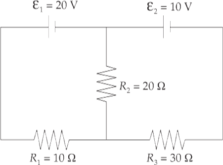
Solution. First let’s label some points in the circuit.
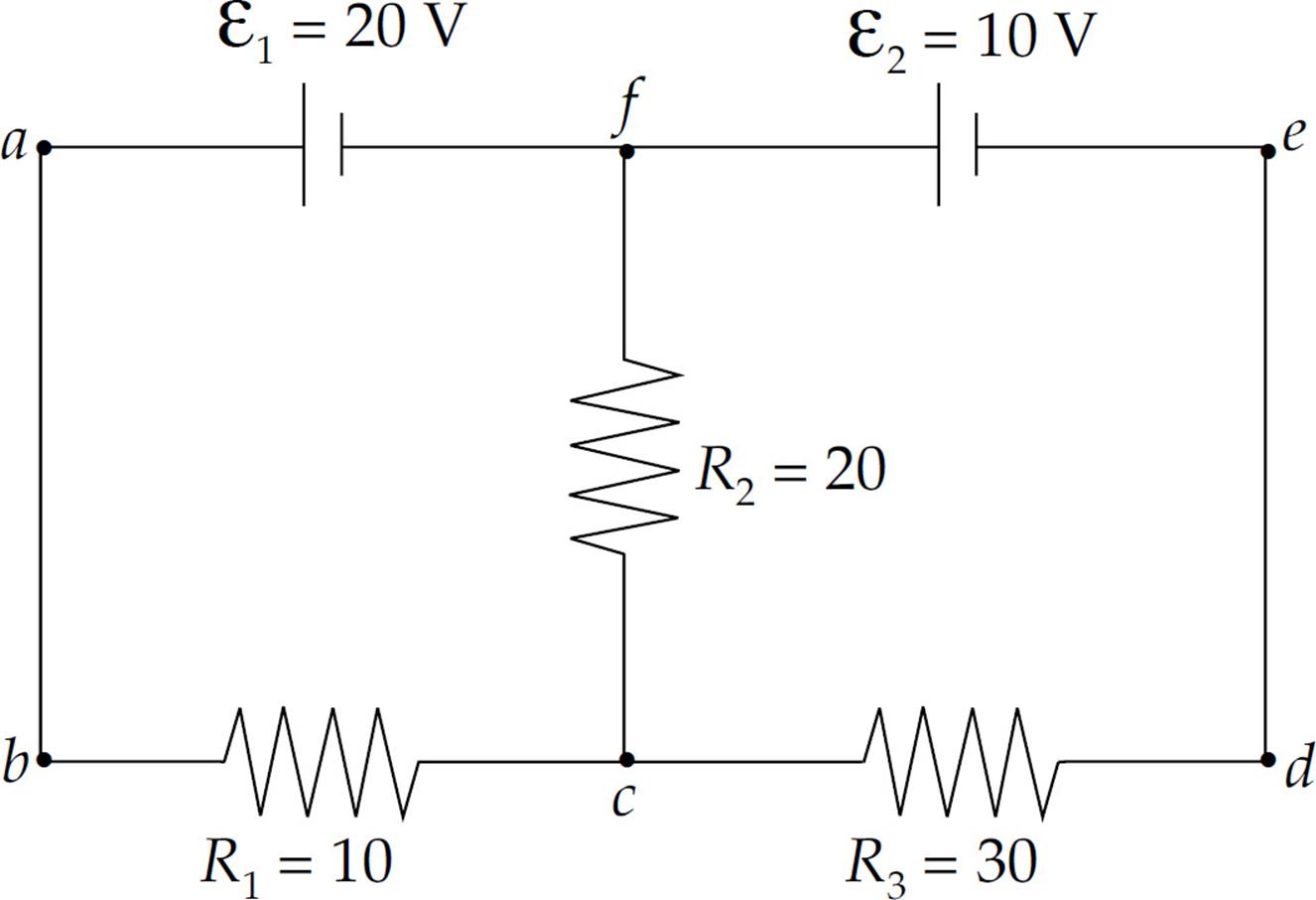
The points c and f are junctions (nodes). We have two nodes and three branches: one branch is fabc, another branch is cdef, and the third branch is cf. Each branch has one current throughout. If we label the current in fabc I1 and the current in branch cdef I2 (with the directions as shown in the diagram below), then the current in branch cf must be I1 – I2, by the Junction Rule: I1 comes into c, and a total of I2 + (I1 – I) = I1 comes out.
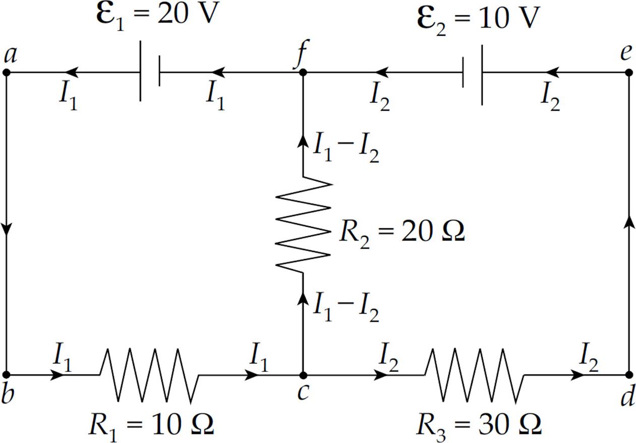
Now pick a loop; say, abcfa. Starting at a, we go to b, then across R1 in the direction of the current, so the potential drops by I1R1. Then we move to c, then up through R2 in the direction of the current, so the potential drops by (I1 – I2)R2. Then we reach f, turn left and travel through ε1from the negative to the positive terminal, so the potential increases by ε1. We now find ourselves back at a. By the Loop Rule, the total change in potential around this closed loop must be zero, and
–I1R1 – (I1 – I2)R2 + ε1 = 0 (1)
Since we have two unknowns (I1 and I2), we need two equations, so now pick another loop; let’s choose cdefc. From c to d, we travel across the resistor in the direction of the current, so the potential drops by I2R3. From e to f, we travel through ε2 from the positive to the negative terminal, so the potential drops by ε2. Heading down from f to c, we travel across R2 but in the direction opposite to the current, so the potential increases by (I1 – I2)R2. At c, our loop is completed, so
–I2R3 – ε2 + (I1 – I2)R2 = 0 (2)
Substituting in the given numerical values for R1, R2, R3, ε1, and ε2, and simplifying, these two equations become
3I1 – 2I2 = 2 (1´)
2I1 – 5I2 = 1 (2´)
Solving this pair of simultaneous equations, we get
I1 = ![]() A = 0.73 A and I2 =
A = 0.73 A and I2 = ![]() A = 0.09 A
A = 0.09 A
So the current through R2 is I1 – I2 = ![]() A = 0.64 A.
A = 0.64 A.
The choice of directions of the currents at the beginning of the solution was arbitrary. Don’t worry about trying to guess the actual direction of the current in a particular branch. Just pick a direction, stick with it, and obey the Junction Rule. At the end, when you solve for the values of the branch current, a negative value will alert you that the direction of the current is actually opposite to the direction you originally chose for it in your diagram.
Example 10 In the circuit diagram below, Resistors ![]() and
and ![]() have fixed resistances (R1 and R3, respectively), which are known. Resistor
have fixed resistances (R1 and R3, respectively), which are known. Resistor ![]() is a variable (or adjustable) resistor, and the resistance of Resistor
is a variable (or adjustable) resistor, and the resistance of Resistor ![]() is unknown.
is unknown.
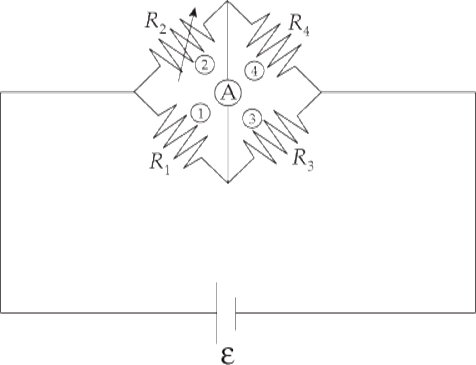
Show that if Resistor ![]() is adjusted until the ammeter shown registers no current through its branch, then
is adjusted until the ammeter shown registers no current through its branch, then
R1R4 = R2R3
(This circuit arrangement is known as a Wheatstone bridge.)
Solution. If no current flows through the ammeter, then Resistors ![]() and
and ![]() are in series, and so are Resistors
are in series, and so are Resistors ![]() and
and ![]() . Therefore, the current flowing through
. Therefore, the current flowing through ![]() and
and ![]() is equal to I1-3 = ε/(R1 + R3). Similarly, the current flowing through
is equal to I1-3 = ε/(R1 + R3). Similarly, the current flowing through ![]() and
and ![]() is I2-4 = ε/(R2 + R4). Now consider the three points marked a, b, and c:
is I2-4 = ε/(R2 + R4). Now consider the three points marked a, b, and c:
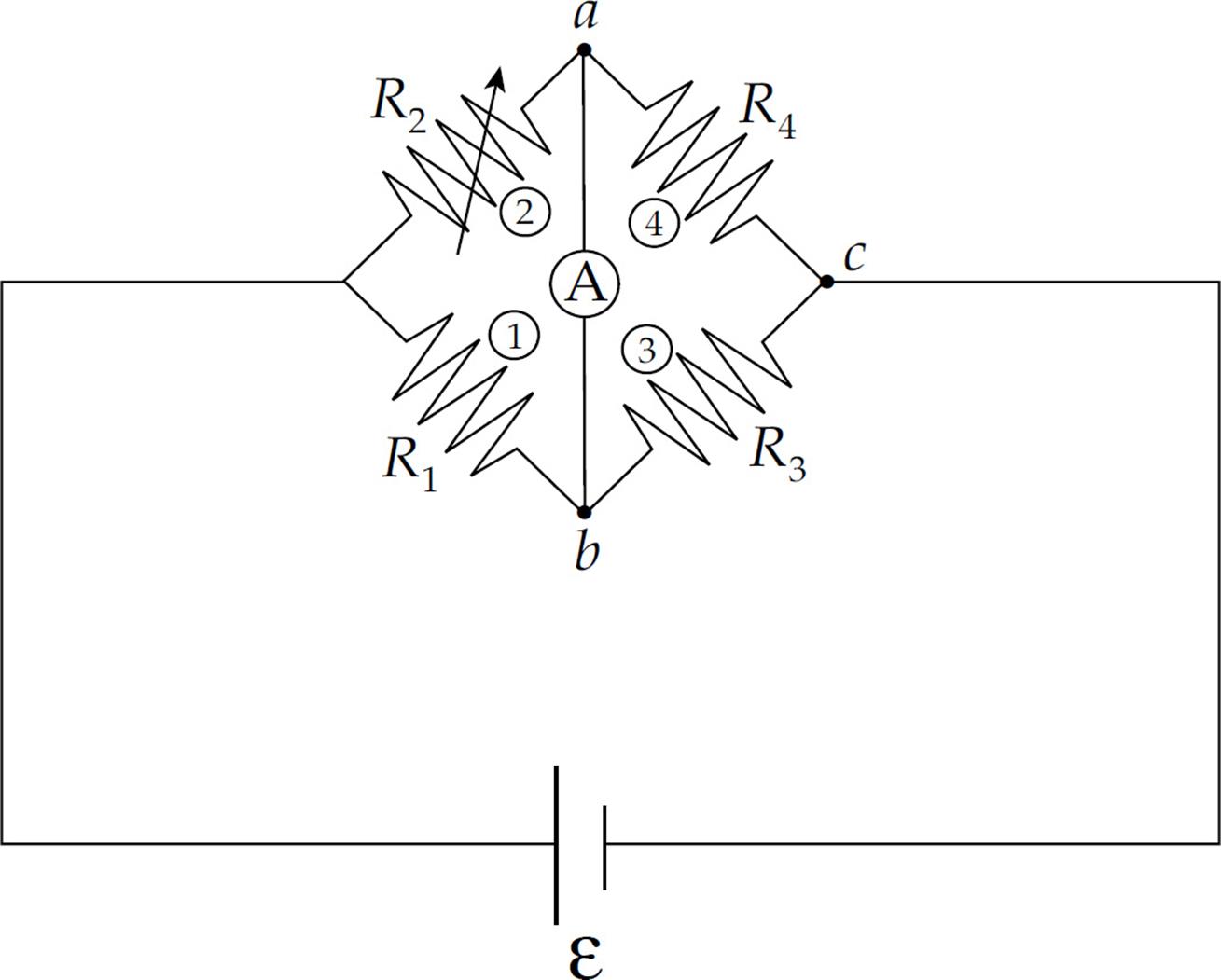
Since no current flows between Points a and b, there must be no potential difference between a and b; they’re at the same potential. So the voltage drop from a to c must equal the voltage drop from b to c. The voltage drop from a to c is
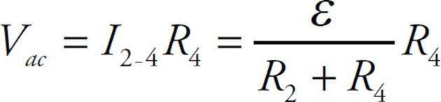
and the voltage drop from b to c is
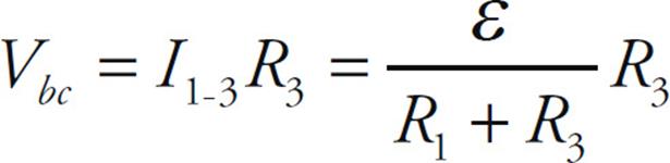
Setting these equal to each other, we get
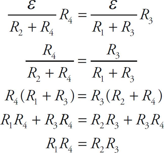
By knowing R1, R2, and R3, we can solve for the unknown resistance: R4 = R2R3/R1.
RESISTANCE–CAPACITANCE (RC) CIRCUITS
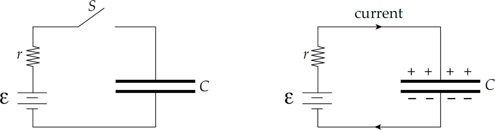
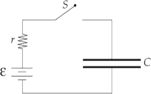
Capacitors are typically charged by batteries. Once the switch in the diagram on the left is closed, electrons are attracted to the positive terminal of the battery and leave the top plate of the capacitor. Electrons also accumulate on the bottom plate of the capacitor, and this continues until the voltage across the capacitor plates matches the emf of the battery. When this condition is reached, the current stops and the capacitor is fully charged.
Charging or Discharging a Capacitor in an RC Circuit
When a battery is hooked up to an uncharged capacitor and current begins to flow, the current is not constant. So far, we have assumed that the currents in our circuits have been constant, but RC circuits are different.
Charging a Capacitor
Consider the RC circuit shown below, where the charge on the capacitor is zero:
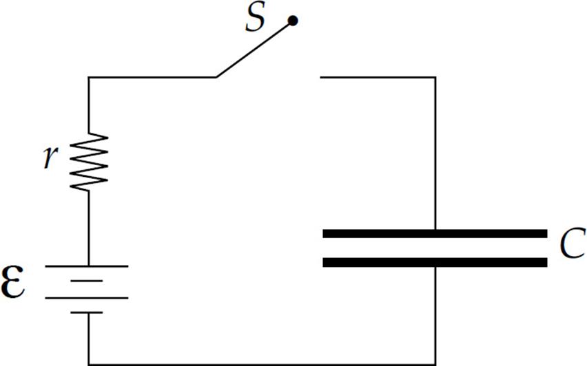
When the switch is closed (time t = 0), there is no charge on the capacitor, which means that there’s no voltage across the capacitor, so Kirchhoff’s Loop Rule gives us ε – IR = 0, and the initial current in the circuit is I = ε/R. But, as time passes, charge begins to accumulate on the capacitor, and a voltage is created that opposes the emf of the battery. At any time t after the switch is closed, Kirchhoff’s Loop Rule gives us:
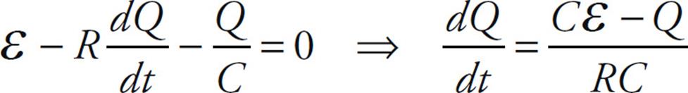
ε – I(t)R – V(t) = 0
where I(t) is the current at time t and V(t) is the voltage across the capacitor at time t. Since V(t) = Q(t)/C and I(t) = dQ(t)/dt, the equation above becomes
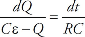
We will solve for Q(t) using separation of variables.
Now integrate both sides to get
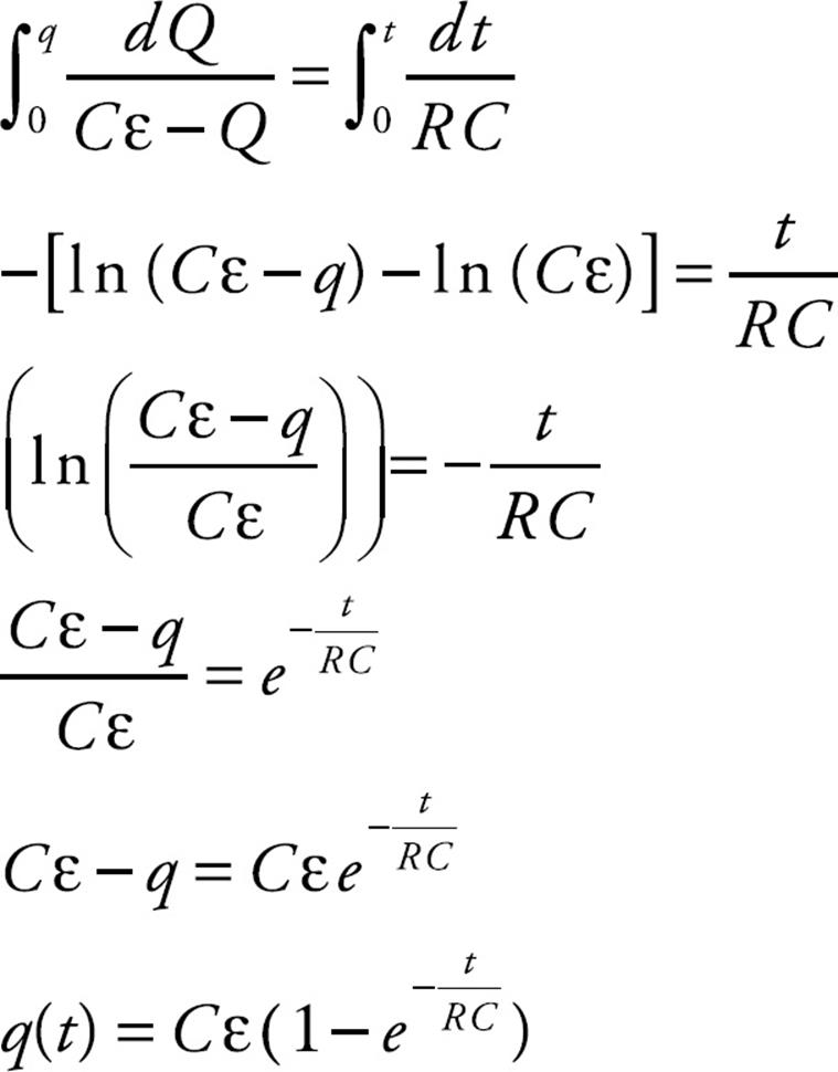
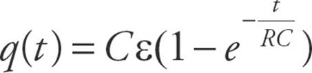
This gives us an equation, q(t), for how the charge on the capacitor changes over time.
The product Cε is equal to the final charge on the capacitor (remember that Q = CV). The quantity RC that appears in the exponent is called the time constant for the circuit and is represented by τ:
τ = RC
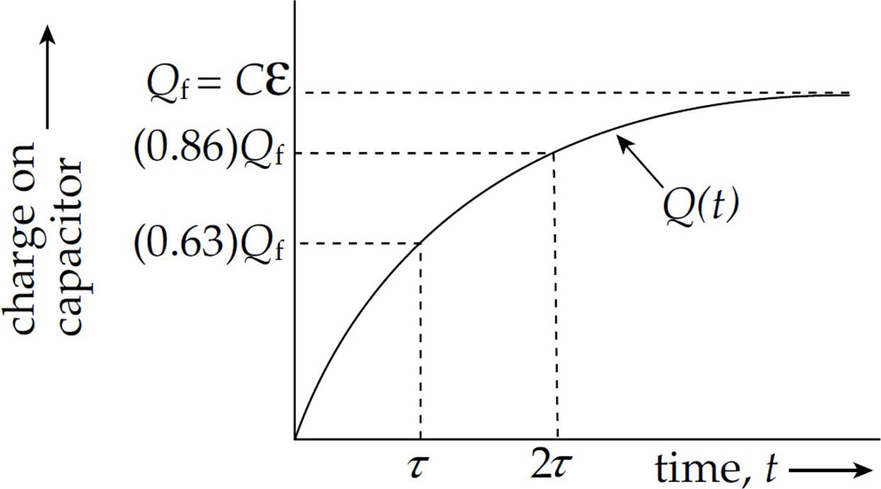
Therefore, letting Qf replace the quantity Cε, the equation above becomes
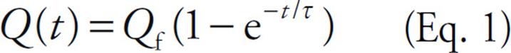
What does the time constant, τ, say about the circuit? It says that, after a time interval of τ has elapsed, the charge on the capacitor is

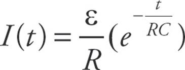
Therefore, the greater the value of τ, the more slowly the capacitor charges. By differentiating Eq. 1 with respect to t,
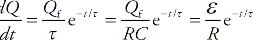
we can get the current in the circuit as a function of time:
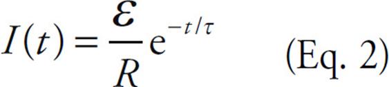
Therefore, the charge builds up gradually on the capacitor,
as the current in the circuit drops gradually to zero:
Discharging a Capacitor
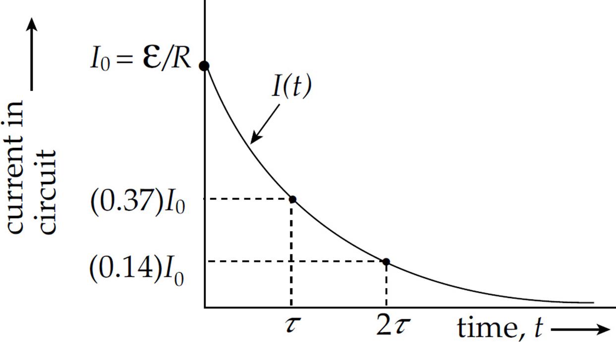
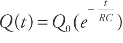
Consider the RC circuit shown below, where the charge on the capacitor is Q0:
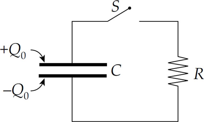
When the switch is closed (time t = 0), the voltage across the capacitor is V0 = Q0/C, so V0 – IR = 0, and the initial current in the circuit is I0 = V0/R. But as time passes, charge leaks off the capacitor and its voltage decreases, which causes the current to decrease.
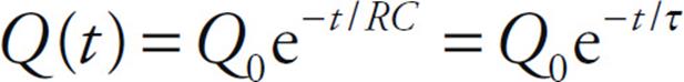
The equation for Q(t) can be derived by the method of separation of variables as in the charging example. It is
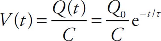
The voltage across the plates as a function of time is
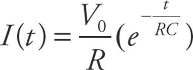
and, by using the equation I(t) = –dQ/dt, the current in the circuit is
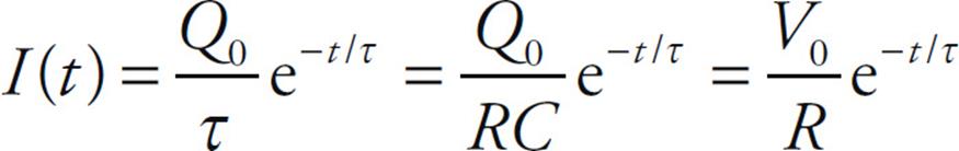
Example 11 In the circuit below, ε = 20 V, R = 1000Ω, and C = 2 mF. If the capacitor is initially uncharged, how long will it take (after the switch S is closed) for the capacitor to be 99% charged?
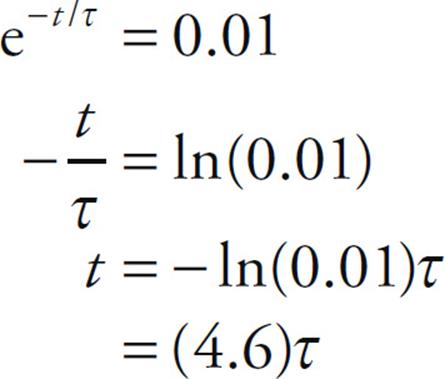
Solution. The equation Q(t) = Qf(1 - e-t/τ), where τ = RC, gives the charge on the capacitor as a function of time. If we want Q(t) to equal 0.99Qf, then we have to wait until time t, when e-t/τ = 0.01. Solving this equation for t, we get
Since the time constant is
τ = RC = (1000 Ω)(2 mF) = 2 s
the time required is (4.6)τ = (4.6)(2 s) = 9.2 s.
Example 12
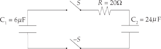
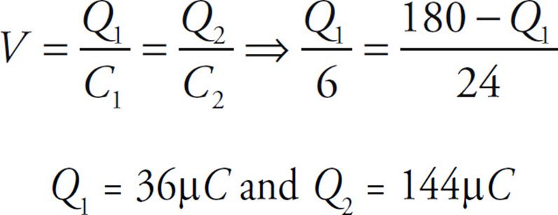
Capacitors 1 and 2, of capacitance C1 = 6 µF and C2 = 24 µF, respectively, are connected in a circuit as shown above with a resistor of resistance R = 20 Ω and two switches. Capacitor 1 is initially charged to a voltage Vo = 30 V, and capacitor 2 is initially uncharged. Both of the switches S are then closed simultaneously.
(a) What is the initial current in the circuit?
(b) What are the final charges on each of the capacitors 1 and 2 after equilibrium has been reached?
Solution.
(a) Use Ohm’s Law to solve for the initial current. The voltage will decrease with time, but the initial voltage is 30 V.
V = IR ⇒ 30 = I(20) ⇒ I = 1.5 A
(b) The initial charge stored on Capacitor 1 is Q = CV = (6)(30) = 180 µC. This charge will redistribute until equilibrium is reached and both capacitors have the same potential difference across them. Rearrange  , to solve for the potential difference across each capacitor:
  .
.
CHAPTER 13 REVIEW QUESTIONS
The answers and explanations can be found in Chapter 16.
Section I: Multiple Choice
1. A wire made of brass and a wire made of silver have the same length, but the diameter of the brass wire is 4 times the diameter of the silver wire. The resistivity of brass is 5 times greater than the resistivity of silver. If RB denotes the resistance of the brass wire and RS denotes the resistance of the silver wire, which of the following is true?
(A) RB = ![]() RS
RS
(B) RB = ![]() RS
RS
(C) RB = ![]() RS
RS
(D) RB = ![]() RS
RS
(E) RB = ![]() RS
RS
2. For an ohmic conductor, doubling the voltage without changing the resistance will cause the current to
(A) decrease by a factor of 4
(B) decrease by a factor of 2
(C) remain unchanged
(D) increase by a factor of 2
(E) increase by a factor of 4
3. If a 60-watt light bulb operates at a voltage of 120 V, what is the resistance of the bulb?
(A) 2 Ω
(B) 30 Ω
(C) 240 Ω
(D) 720 Ω
(E) 7200 Ω
4. A battery whose emf is 40 V has an internal resistance of 5 Ω. If this battery is connected to a 15 Ω resistor R, what will the voltage drop across R be?
(A) 10 V
(B) 30 V
(C) 40 V
(D) 50 V
(E) 70 V
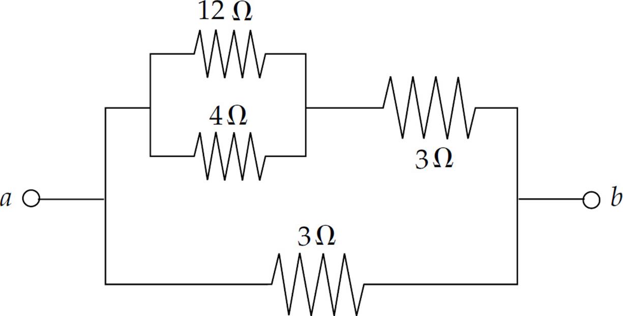
5. Determine the equivalent resistance between points a and b in the figure above.
(A) 0.167 Ω
(B) 0.25 Ω
(C) 0.333 Ω
(D) 1.5 Ω
(E) 2 Ω
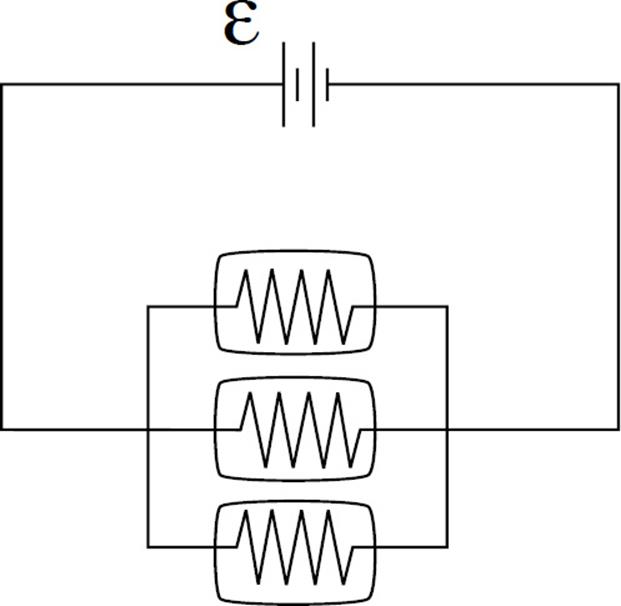
6. Three identical light bulbs are connected to a source of emf, as shown in the diagram above. What will happen if the middle bulb burns out?
(A) All the bulbs will go out.
(B) The light intensity of the other two bulbs will decrease (but they won’t go out).
(C) The light intensity of the other two bulbs will increase.
(D) The light intensity of the other two bulbs will remain the same.
(E) More current will be drawn from the source of emf.
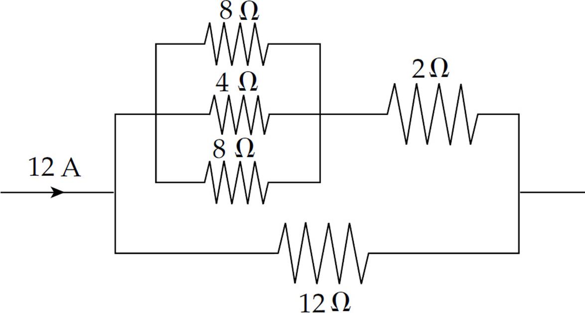
7. What is the voltage drop across the 12-ohm resistor in the portion of the circuit shown above?
(A) 24 V
(B) 36 V
(C) 48 V
(D 72 V
(E) 144 V
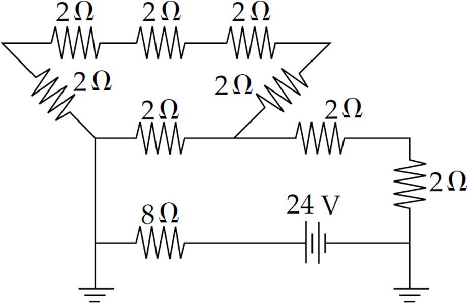
8. What is the current through the 8-ohm resistor in the circuit shown above?
(A) 0.5 A
(B) 1.0 A
(C) 1.25 A
(D) 1.5 A
(E) 3.0 A
9. How much energy is dissipated as heat in 20 s by a 100 Ω resistor that carries a current of 0.5 A?
(A) 50 J
(B) 100 J
(C) 250 J
(D) 500 J
(E) 1000 J
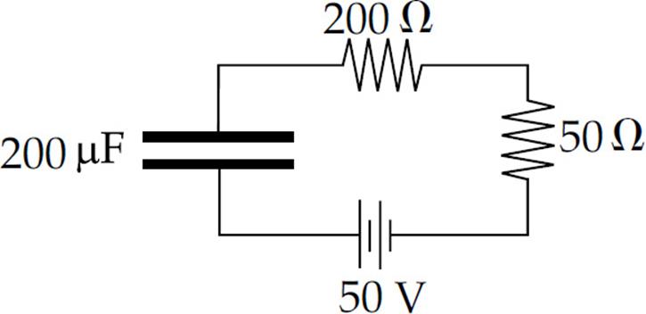
10. What is the time constant for the circuit above?
(A) 0.01 s
(B) 0.025 s
(C) 0.04 s
(D) 0.05 s
(E) 0.1 s
Section II: Free Response
1. Consider the following circuit:
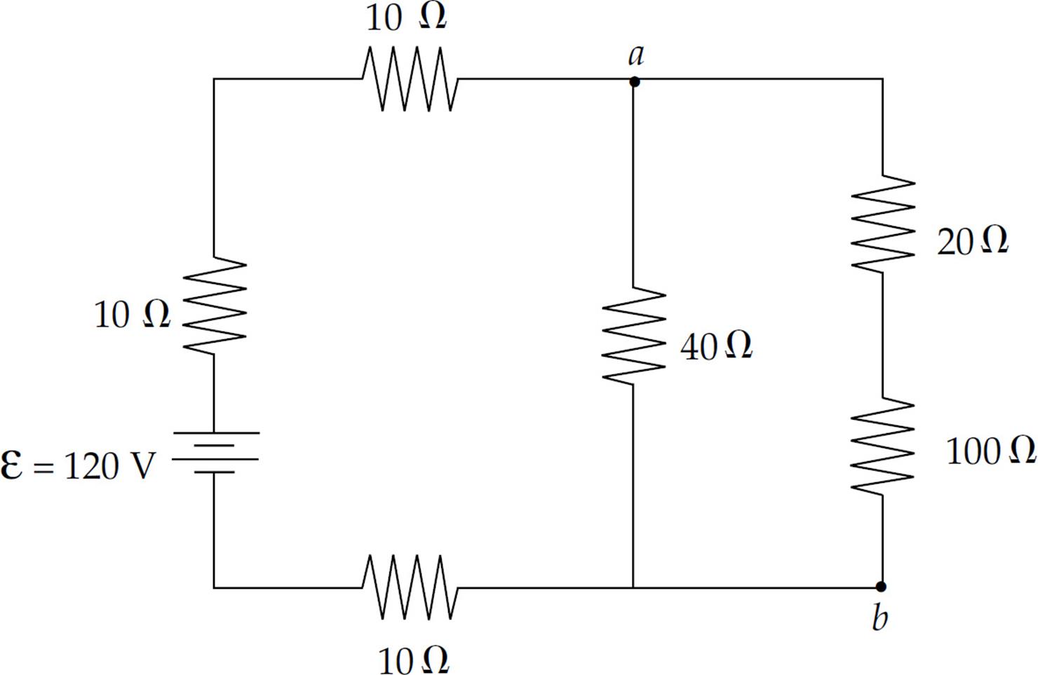
(a) At what rate does the battery deliver energy to the circuit?
(b) Find the current through the 20 Ω resistor.
(c) (i) Determine the potential difference between points a and b.
(ii) At which of these two points is the potential higher?
(d) Find the energy dissipated by the 100 Ω resistor in 10 s.
(e) Given that the 100 Ω resistor is a solid cylinder that’s 4 cm long, composed of a material whose resistivity is 0.45 Ω·m, determine its radius.
2. The diagram below shows an uncharged capacitor, two resistors, and a battery whose emf is ε.
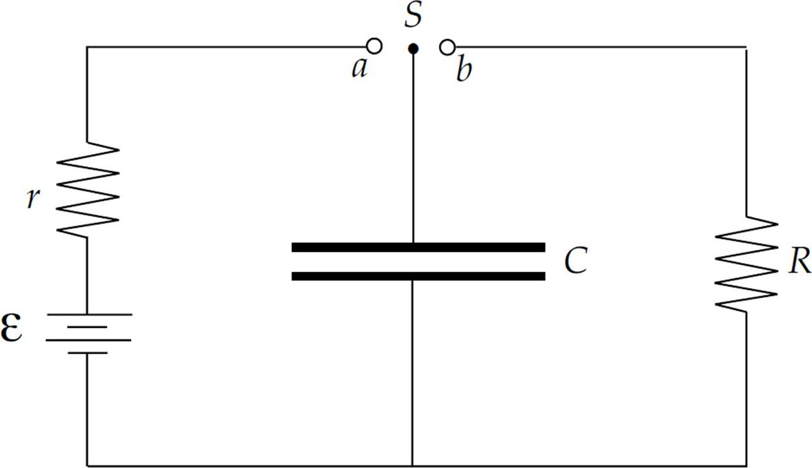
The switch S is turned to point a at time t = 0.
(Express all answers in terms of C, r, R, ε, and fundamental constants.)
(a) Determine the current through r at time t = 0.
(b) Compute the time required for the charge on the capacitor to reach one-half its final value.
(c) When the capacitor is fully charged, which plate is positively charged?
(d) Determine the electrical potential energy stored in the capacitor when the current through r is zero.
When the current through r is zero, the switch S is then moved to Point b; for the following parts, consider this event time t = 0.
(e) Determine the current through R as a function of time.
(f) Find the power dissipated in R as a function of time.
(g) Determine the total amount of energy dissipated as heat by R.
Summary
General Information
- Current is the flow rate of charge:
 . The units are amps (A).
 - The resistance of length of material depends on the resistivity, length, and cross-sectional area:
 . The units of resistance are ohms (Ω).
 - Many electrical devices obey Ohm’s Law: ΔV = IR
- Power is the rate that electrical energy is transferred:
Circuits with Resistors
- The equivalent resistance of resistors added in series is the sum of the resistance of each device:
- The reciprocal of the equivalent resistance of resistors added in parallel is the sum of the reciprocals of each resistor:
Kirchhoff’s Rules:
1. The Loop Rule. The sum of the potential differences around a closed loop in a circuit must be zero: 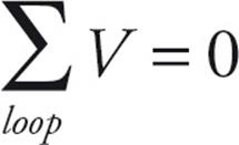
2. The Junction (Node) Rule. The total current that enters a junction must equal the total current that leaves the junction.
Circuits with Resistors and Capacitors (RC Circuits)
- When a battery is connected to a resistor and uncharged capacitors in a circuit, the charge builds up on the capacitor exponentially. This is due to the fact that as more charge is added to the capacitor it becomes more difficult for additional charge to be added. The equation for the charge buildup is
 .
. - The quantity RC is called the time constant: τ = RC
- During this time the current is decreasing exponentially because the capacitor is acting like an opposing battery as it charges up. The equation for the current is
 .
. - When a charged capacitor that has an initial voltage, V0, and initial charge, Q0, is connected in a circuit to a resistor both the charge on the plate and the current through the circuits decrease exponentially. The equations for the charge and the current are given by:
 and
and