AP Physics B Exam
14 Electromagnetic Induction
INTRODUCTION
In Chapter 13, we learned that electric currents generate magnetic fields, and we will now see how magnetism can generate electric currents.
MOTIONAL EMF
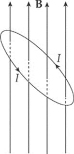
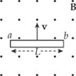
The figure below shows a conducting wire of length ![]() , moving with constant velocity v in the plane of the page through a uniform magnetic field B that”s perpendicular to the page. The magnetic field exerts a force on the moving conduction electrons in the wire. With B pointing into the page, the direction of v is to the right, so the magnetic force, FB, for positive charges, would be upward by the right-hand rule, so FB on these electrons (which are negatively charged) is downward.
, moving with constant velocity v in the plane of the page through a uniform magnetic field B that”s perpendicular to the page. The magnetic field exerts a force on the moving conduction electrons in the wire. With B pointing into the page, the direction of v is to the right, so the magnetic force, FB, for positive charges, would be upward by the right-hand rule, so FB on these electrons (which are negatively charged) is downward.
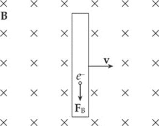
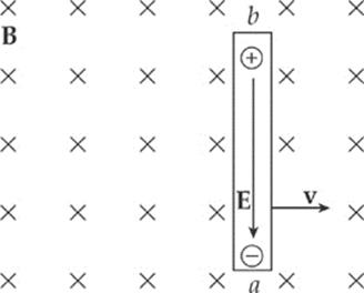
As a result, electrons will be pushed to the lower end of the wire, which will leave an excess of positive charge at its upper end. This separation of charge creates a uniform electric field, E, within the wire (pointing downward).
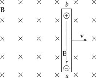
A charge q in the wire feels two forces: an electric force, FE = qE, and a magnetic force, FB = qvBsin θ = qvB, because θ = 90°.
If q is negative, FE is upward and FB is downward; if q is positive, FE is downward and FB is upward. So, in both cases, the forces act in opposite directions. Once the magnitude of FE equals the magnitude of FB, the charges in the wire are in electromagnetic equilibrium. This occurs whenqE = qvB; that is, when E = vB.
The presence of the electric field creates a potential difference between the ends of the rod. Since negative charge accumulates at the lower end (which we”ll call point a) and positive charge accumulates at the upper end (point b), point b is at a higher electric potential.
The potential difference Vba is equal to E![]() and, since E = vB, the potential difference can be written as vB
and, since E = vB, the potential difference can be written as vB![]() .
.
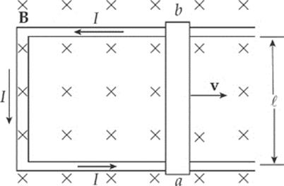
Now, imagine that the rod is sliding along a pair of conducting rails connected at the left by a stationary bar. The sliding rod now completes a rectangular circuit, and the potential difference Vba causes current to flow.
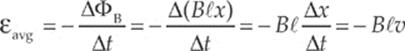
The motion of the sliding rod through the magnetic field creates an electromotive force, called motional emf:
ε = B![]() v
v
The existence of a current in the sliding rod causes the magnetic field to exert a force on it. Using the formula FB = BI![]() , the fact that
, the fact that ![]() points upward (in the direction of the current) and B is into the page, tells us that the direction of FB on the rod is to the left. An external agent must provide this same amount of force to the right to maintain the rod”s constant velocity and keep the current flowing. The power that the external agent must supply is P = Fv = I
points upward (in the direction of the current) and B is into the page, tells us that the direction of FB on the rod is to the left. An external agent must provide this same amount of force to the right to maintain the rod”s constant velocity and keep the current flowing. The power that the external agent must supply is P = Fv = I![]() Bv, and the electrical power delivered to the circuit is P = IVba = Iε = IvB
Bv, and the electrical power delivered to the circuit is P = IVba = Iε = IvB![]() . Notice that these two expressions are identical. The energy provided by the external agent is transformed first into electrical energy and then thermal energy as the conductors making up the circuit dissipate heat.
. Notice that these two expressions are identical. The energy provided by the external agent is transformed first into electrical energy and then thermal energy as the conductors making up the circuit dissipate heat.
FARADAY”S LAW OF ELECTROMAGNETIC INDUCTION
Electromotive force can be created by the motion of a conductor through a magnetic field, but there”s another way to create an emf from a magnetic field. (We have used A to represent the area vector, which points in a direction perpendicular to the plane of the given surface.)
The magnetic flux, ΦB, through an area A is equal to the product of A and the magnetic field perpendicular to it: ΦB = B⊥ A = B · A = BA cos θ.
Example 14.1 The figure below shows two views of a circular loop of radius 3 cm placed within a uniform magnetic field, B (magnitude 0.2 T).
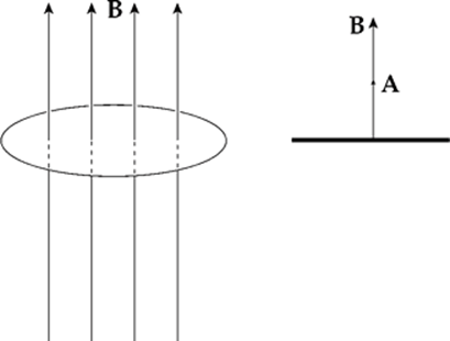
(a) What”s the magnetic flux through the loop?
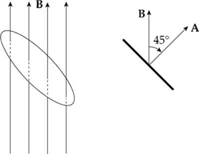
(b) What would be the magnetic flux through the loop if the loop were rotated 45°?
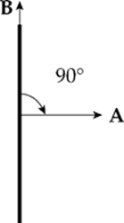
(c) What would be the magnetic flux through the loop if the loop were rotated 90°?
Solution.
(a) Since B is parallel to A, the magnetic flux is equal to BA:
ΦB = BA = B · πr2 = (0.2 T) · π(0.03 m)2 = 5.7 × 10⁻⁴ T·m2
The SI unit for magnetic flux, the tesla·meter2, is called a weber (abbreviated Wb). So ΦB = 5.7 × 10⁻⁴ Wb.
(b) Since the angle between B and A is 45°, the magnetic flux through the loop is
ΦB = BA cos 45° = B · πr2 cos 45°= (0.2 T) · π(0.03 m)2 cos 45° = 4.0 × 10⁻⁴ Wb
(c) If the angle between B and A is 90°, the magnetic flux through the loop is zero, since cos 90° = 0.
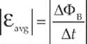
The concept of magnetic flux is crucial, because changes in magnetic flux induce emf. According to Faraday”s Law of Electromagnetic Induction, the magnitude of the emf induced in a circuit is equal to the rate of change of the magnetic flux through the circuit. This can be written mathematically in the form
This induced emf can produce a current, which will then create its own magnetic field. The direction of the induced current is determined by the polarity of the induced emf and is given by Lenz”s Law: The induced current will always flow in the direction that opposes the change in magnetic flux that produced it. If this were not so, then the magnetic flux created by the induced current would magnify the change that produced it, and energy would not be conserved. Lenz”s Law can be included mathematically with Faraday”s Law by the introduction of a minus sign; this leads to a single equation that expresses both results:
Example 14.2 The circular loop of Example 14.1 rotates at a constant angular speed through 45° in 0.5 s.

(a) What”s the induced emf in the loop?
(b) In which direction will current be induced to flow?
Solution.
(a) As we found in Example 14.1, the magnetic flux through the loop changes when the loop rotates. Using the values we determined earlier, Faraday”s Law gives

(b) The original magnetic flux was 5.7 × 10⁻⁴ Wb upward, and was decreased to 4.0 × 10⁻⁴ Wb. So the change in magnetic flux is –1.7 × 10⁻⁴ Wb upward, or, equivalently, ∆ΦB = 1.7 × 10⁻⁴ Wb, downward. To oppose this change we would need to create some magnetic flux upward. The current would be induced in the counterclockwise direction (looking down on the loop), because the right-hand rule tells us that then the current would produce a magnetic field that would point up.
The current will flow only while the loop rotates, because emf is induced only when magnetic flux is changing. If the loop rotates 45° and then stops, the current will disappear.
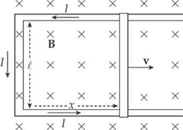
Example 14.3 Again consider the conducting rod that”s moving with constant velocity v along a pair of parallel conducting rails (separated by a distance ![]() ), within a uniform magnetic field, B:
), within a uniform magnetic field, B:
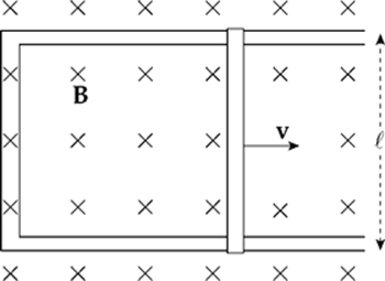
Find the induced emf and the direction of the induced current in the rectangular circuit.
Solution. The area of the rectangular loop is ![]() x, where x is the distance from the left-hand bar to the moving rod:
x, where x is the distance from the left-hand bar to the moving rod:
Because the area is changing, the magnetic flux through the loop is changing, which means that an emf will be induced in the loop. To calculate the induced emf, we first write ΦB = BA = B![]() x, then since ∆x/∆t = v, we get
x, then since ∆x/∆t = v, we get
We can figure out the direction of the induced current from Lenz”s Law. As the rod slides to the right, the magnetic flux into the page increases. How do we oppose an increasing into-the-page flux? By producing out-of-the-page flux. In order for the induced current to generate a magnetic field that points out of the plane of the page, the current must be directed counterclockwise (according to the right-hand rule).
Note that the magnitude of the induced emf and the direction of the current agree with the results we derived earlier, in the section on motional emf.
This example also shows how a violation of Lenz”s Law would lead directly to a violation of the Law of Conservation of Energy. The current in the sliding rod is directed upward, as given by Lenz”s Law, so the conduction electrons are drifting downward. The force on these drifting electrons—and thus, the rod itself—is directed to the left, opposing the force that”s pulling the rod to the right. If the current were directed downward, in violation of Lenz”s Law, then the magnetic force on the rod would be to the right, causing the rod to accelerate to the right with ever-increasing speed and kinetic energy, without the input of an equal amount of energy from an external agent.
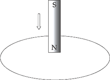
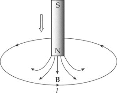
Example 14.4 A permanent magnet creates a magnetic field in the surrounding space. The end of the magnet at which the field lines emerge is designated the north pole (N), and the other end is the south pole (S):

(a) The figure below shows a bar magnet moving down, through a circular loop of wire. What will be the direction of the induced current in the wire?
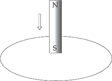
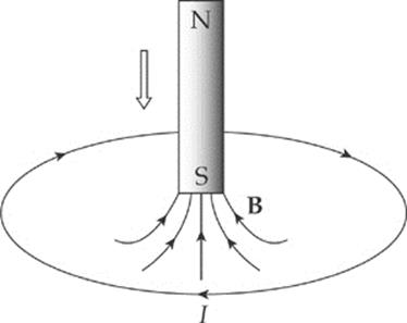
(b) What will be the direction of the induced current in the wire if the magnet is moved as shown in the following diagram?
Solution.
(a) The magnetic flux down, through the loop, increases as the magnet is moved. By Lenz”s Law, the induced emf will generate a current that opposes this change. How do we oppose a change of more flux downward? By creating flux upward. So, according to the right-hand rule, the induced current must flow counterclockwise (because this current will generate an upward-pointing magnetic field):
(b) In this case, the magnetic flux through the loop is upward and, as the south pole moves closer to the loop, the magnetic field strength increases so the magnetic flux through the loop increases upward. How do we oppose a change of more flux upward? By creating flux downward. Therefore, in accordance with the right-hand rule, the induced current will flow clockwise (because this current will generate a downward-pointing magnetic field):
Example 14.5 A square loop of wire 2 cm on each side contains 5 tight turns and has a total resistance of 0.0002 Ω. It is placed 20 cm from a long, straight, current-carrying wire. If the current in the straight wire is increased at a steady rate from 20 A to 50 A in 2 s, determine the magnitude and direction of the current induced in the square loop. (Because the square loop is at such a great distance from the straight wire, assume that the magnetic field through the loop is uniform and equal to the magnetic field at its center.)
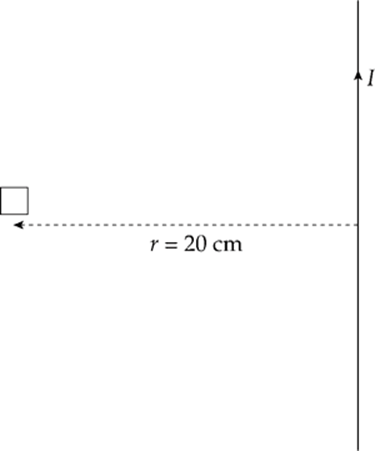
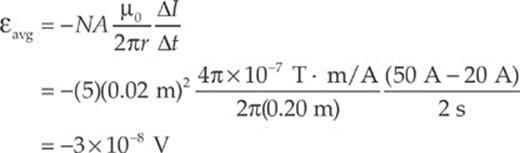
Solution. At the position of the square loop, the magnetic field due to the straight wire is directed out of the plane of the page and its strength is given by the equation B = (μ0/2π)(I/r). As the current in the straight wire increases, the magnetic flux through the turns of the square loop changes, inducing an emf and current. There are N = 5 turns; Faraday”s Law becomes εavg = –N(∆ΦB/∆t), and

Substituting the given numerical values, we get
The magnetic flux through the loop is out of the page and increases as the current in the straight wire increases. To oppose an increasing out-of-the-page flux, the direction of the induced current should be clockwise, thereby generating an into-the-page magnetic field (and flux).
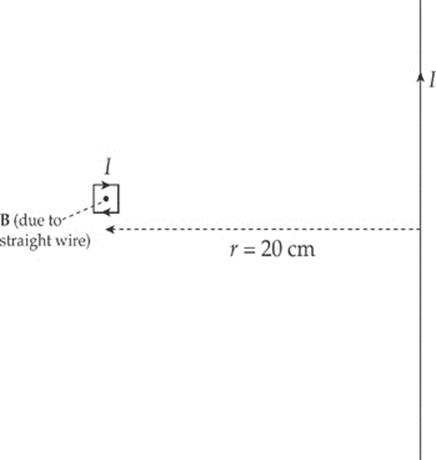
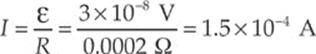
The value of the current in the loop will be
CHAPTER 14 REVIEW QUESTIONS
Solutions can be found in Chapter 18.
SECTION I: MULTIPLE CHOICE
1. A metal rod of length L is pulled upward with constant velocity v through a uniform magnetic field B that points out of the plane of the page.
What is the potential difference between points a and b?
(A) 0
(B) ![]() vBL, with point a at the higher potential
vBL, with point a at the higher potential
(C) ![]() vBL, with point b at the higher potential
vBL, with point b at the higher potential
(D) vBL, with point a at the higher potential
(E) vBL, with point b at the higher potential
2. A conducting rod of length 0.2 m and resistance 10 ohms between its endpoints slides without friction along a U-shaped conductor in a uniform magnetic field B of magnitude 0.5 T perpendicular to the plane of the conductor, as shown in the diagram below.
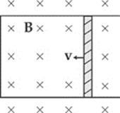
If the rod is moving with velocity v = 3 m/s to the left, what is the magnitude and direction of the current induced in the rod?
|
Current |
Direction |
|
|
(A) |
0.03 A |
down |
|
(B) |
0.03 A |
up |
|
(C) |
0.3 A |
down |
|
(D) |
0.3 A |
up |
|
(E) |
3 A |
down |
3. In the figure below, a small, circular loop of wire (radius r) is placed on an insulating stand inside a hollow solenoid of radius R. The solenoid has n turns per unit length and carries a counterclockwise current I. If the current in the solenoid is decreased at a steady rate of a amps/s, determine the induced emf, ε, and the direction of the induced current in the loop.
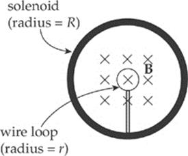
(A) ε = μ0πnr2a; induced current is clockwise
(B) ε = μ0πnr2a; induced current is counterclockwise
(C) ε = μ0πnR2a; induced current is clockwise
(D) ε = μ0πnR2a; induced current is counterclockwise
(E) ε = μ0πInR2a; induced current is counterclockwise
4. In the figures below, a permanent bar magnet is below a loop of wire. It is pulled upward with a constant velocity through the loop of wire as shown in figure b.
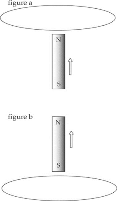
Which of the following best describes the direction(s) of the current induced in the loop (looking down on the loop from above)?
(A) Always clockwise
(B) Always counterclockwise
(C) First clockwise, then counterclockwise
(D) First counterclockwise, then clockwise
(E) No current will be induced in the loop
5. A square loop of wire (side length = s) surrounds a long, straight wire such that the wire passes through the center of the square.
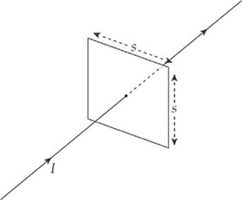
If the current in the wire is I, determine the current induced in the square loop.
(A) 
(B) ![]()
(C) ![]()
(D) 
(E) 0
SECTION II: FREE RESPONSE
1. A rectangular wire is pulled through a uniform magnetic field of 2T going into the page as shown. The resistor has a resistance of 20 Ω.
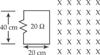
(a) What is the voltage across the resistor as the wire is pulled horizontally at a velocity of 1 m/s and it just enters the field?
(b) What is the current through the circuit in the above case and in what direction does it flow?
(c) What would the voltage be if the wire were rotated 90 degrees and pulled horizontally at the same velocity?
(d) What would the velocity have to be in order to maintain the same voltage as in part (a) but with the orientation of part (c)?
SUMMARY
· An electromotive force is produced as a conducting wire”s position changes or as the magnetic field changes. This idea is summarized by ε = B![]() v.
v.
· The flux (φ) tells the amount of something (for this chapter the magnetic field) that goes through a surface. The magnetic flux depends on the strength of the magnetic field, the surface area through which the field passes, and the angle between the two. This idea is summed up by φm =BA cos θ.
· Faraday”s Law of Induction says that if the wire is formed in a loop, an electromagnetic force is produced if the magnetic flux changes with time. This idea can be summarized by  .
.