Homework Helpers: Physics
6 Electric Current and Circuits
Lesson 6–4: Circuits and Schematic Diagrams
Two major skills in this area of physics involve being able to draw and being able to interpret schematic diagrams for circuits. Schematic diagrams are visual representations of circuits, using standard symbols to represent individual components. Another skill involves being able to construct some of the circuits that you create diagrams for, but because that involves materials that don”t come with this book, I can”t help you with that. Hopefully, you will find opportunities in lab or at home to construct some simple circuits, like the homemade flashlight we have been discussing in this chapter.

Series Circuit
There are two main types of circuits for which we will discuss and create diagrams. A series circuit is a circuit in which there is only one pathway for the charges to travel through. The components in a series circuit are arranged end to end.
Because there is only one pathway for the flow of electricity in a series circuit, the current measured at any point in the circuit will be the same. Therefore, the total current in a series circuit (Is) is equal to the current through each of the components. So, the current through each of the bulbs in Figure 6.2 will be the same.
Is = I1 = I2 =. . . Ix
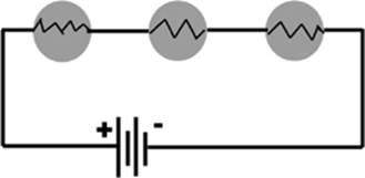
Figure 6.2
Allow me to explain the notation that I used in this, and each of the following formulas. When I write “…Ix,” I mean that you follow this pattern for as many components you have in your circuit. If you only have two, you would stop at I2, but if you have five, you would continue with the pattern until I5.
Each of the bulbs in the picture for a series circuit act as a resistor, so the more you add, the greater the total resistance. If you like the water analogy for electric current, each resistor is like a partial blockage in a water pipe. The effect of numerous blockages is cumulative, resulting in an increase in resistance and a decrease in current. So, the total resistance of the individual resistors in series is equivalent to using one resistor with a resistance of Rs.
Rs = R1 + R2 + . . .Rx
When components, such as our bulbs, are connected in series, the potential difference across the terminals of the battery is equal to the sum of all the potential differences or “voltage drops” across the components.
Vs = V1 + V2 + . . .Vx
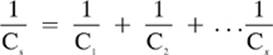
There aren”t any capacitors shown in our diagram of a series circuit (Figure 6.2), but when more than one capacitor is connected in a series, the total capacitance, which is less than the smallest capacitance in the group, can be determined with the following formula:
Parallel Circuits
In a parallel circuit there is more than one pathway for the electricity to travel through. The components in a parallel circuit are arranged side by side, and they can each trace a direct path back to the source of potential difference.
Because each of the bulbs can trace a path back to each side of the battery, the potential difference across each bulb is the same as the potential difference supplied by the battery.
Vp = V1 + V2 + . . .Vx
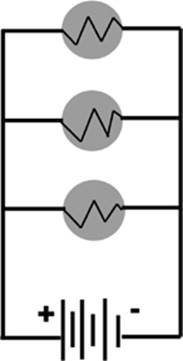
Figure 6.3
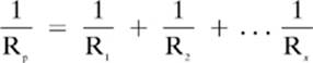
You might think that having more resistors in parallel would lead to more resistance, but, remember, in addition to adding resistors, you are also adding other pathways for the current to flow through. Using the water analogy once again, more water may be able to flow through three pipes, each with a partial blockage, than can flow through one clear pipe. You will find that the total (or equivalent) resistance in a parallel circuit will always be lower than any of the individual resistances, as shown by the formula here:
The current in each of the parallel pathways need not be the same. If the individual bulbs in our circuit each provided different resistances, for example, there would be different amounts of current flowing through each path. You may have heard the expression about “following the path of least resistance.” The current is greatest in the part of the circuit that connects to all of the parallel branches, but current is also greater in the branch with lower resistance that a path with greater resistance.
Ip = I1 + I2 + . . .Ix
There are no capacitors shown in our picture of a parallel circuit, but when capacitors are arranged parallel to each other, the equivalent capacitance may be found with the following formula.
Cp = C1 + C2 + . . .Cx
Comparing Series and Parallel Circuits

Before we get to the harder types of problems involving many calculations, let”s try some easy examples first, just to get used to working with the individual formulas.
Example 1
A 3.0Ω resistor is connected in parallel to a 5.0Ω resistor. What is their equivalent (total) resistance?

Note: If you got an answer that looks like 0.53333, then you still need to find the inverse of that value in order to get the final answer, (0.53333)–1 = 1.875, which we round to 1.9.
Example 2
Three resistors, with resistances of 2.0Ω, 4.0Ω, and 6.0Ω are connected in a series to a 3.0 V battery. Find the equivalent resistance and the current in the circuit.
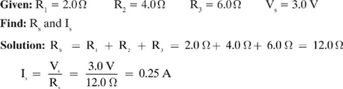
Do you recognize the second formula? It is Ohm”s law from Lesson 6–1.
Example 3
A 4.0Ω and a 6.0Ω resistor are connected in a series with a 3.0 V battery. Find the voltage across each resistor.
![]()
Find: V1 and V2
Solution: First, let”s find the equivalent resistance of the two resistors.
Rs = R1 + R2 = 4.0Ω + 6.0Ω = 10.0Ω
Next, let”s use the voltage and the equivalent resistance to find the current in the circuit.
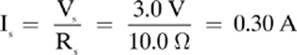
Now, we can find the voltage across each resistor by using Ohm”s law. Make sure that you use the resistance of the individual resistors, not the total.
V1 = Is R1 = (0.30 A)(4.0Ω) = 1.2 V
V2 = Is R2 = (0.30 A)(6.0Ω) = 1.8 V
Notice that the voltage across each of the individual resistors will add up to (1.2 V + 1.8 V = 3.0V) the voltage of the battery. That is a good way to check you answer.
Now, let”s go over some examples of interpreting circuit diagrams together. There are many calculations involved in these types of problems, so we will summarize our results in a table at the end. Your instructor may ask you to do the same.
Example 4
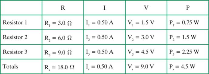
Three resistors, with resistances of 3.0Ω, 6.0Ω, and 9.0Ω, respectively, are connected in a series and attached to a 9.0 V battery, as shown in Figure 6.4. Find the total resistance (Rs), the total current (Is), the current through each resistor, the voltage across each resistor, and the power converted by each resistor.
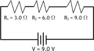
Figure 6.4
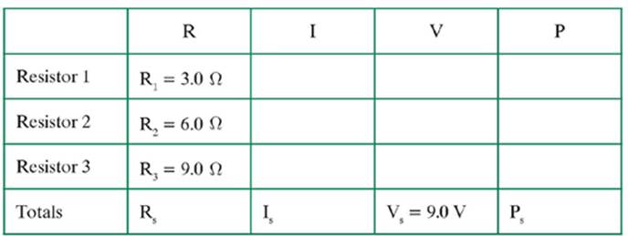
To help organize our calculations and answers, let”s make a chart that shows all of the required and given information. As you find an answer, you can fill in the appropriate spot in the table.
In a series circuit, the logical place to start is to find the total (equivalent) resistance in the circuit.
Rs = R1 + R2 + R3 = 3.0Ω + 6.0Ω + 9.0Ω = 18.0Ω
Then, we can use Ohm”s law to find the total current in the circuit.
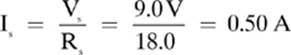
Remember: In a series circuit, current is the same at any point in the circuit, so we can fill in the current through each resistor.
Is = I1 = I2 = I3 = 0.50 A
Now that we know the current and resistance through each resistor, we can find the potential difference across each resistor. Remember to use the individual resistances for these calculations, and check that the total of each potential difference is the same (within rounding) to the voltage of the battery.
V1 = I1 R1 = (0.50 A)(3.0Ω) = 1.5 V
V2 = I2 R2 = (0.50 A)(6.0Ω) = 3.0 V
V3 = I3 R3 = (0.50 A)(9.0Ω) = 4.5 V
The sum of our individual potential drops (1.5 V + 3.0 V + 4.5 V = 9.0 V) is equal to the voltage of our battery, so we can feel confident that we are still on track.
Finally, we need to calculate the power dissipated by each of the resistors. We can choose from a couple of the formulas for electric power that we went over in Lesson 6–3. I will work with the formula P = IV. The current through each resistor is the same, but make sure you use the individual resistances when calculating the power for each resistor.
P1 = I1 V1 = (0.50 A)(1.5 V) = 0.75 W
P2 = I2 V2 = (0.50 A)(3.0 V) = 1.5 W
P3 = I3 V3 = (0.50 A)(4.5 V) = 2.25 W*
*Technically, this value should be rounded to 2.3 W, but this will result in slight differences when I compare the total power.
Now we can check these answers by determining the total power for the circuit with two different methods.
Ps = Is Vs = (0.5 A)(9.0 V) = 4.5 W
Ps = P1 + P2 + P3 = 0.75 W + 1.5 W + 2.25 W = 4.5 W
The fact that we ended up with the same answer for the total power with both calculations, leads me to believe that our calculations are correct. Now, let”s add the values that we have found to our chart.
Now, let”s try a similar problem dealing with a parallel circuit.
Example 5
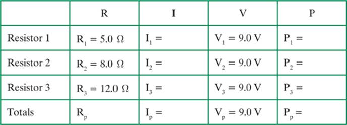
Three resistors, with resistances of 5.0Ω, 8.0Ω, and 12.0Ω, respectively, are connected in a parallel circuit with a 9.0 V battery, as shown in Figure 6.5. Find the total resistance (Rs), the total current (Is), the current through each resistor, the voltage across each resistor, and the power converted by each resistor. The first thing that I think of when I do a parallel problem such as this is that the voltage across each component will be the same as the voltage of the source, because each component can trace a path back to each terminal of the battery.
Vp = V1 = V2 = V3 = 9.0 V
Once again, let”s start a table that will help us organize all of the information that we need to provide to answer this question. We will start with what we already know.
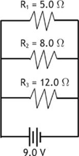
Figure 6.5
I would begin by finding the equivalent resistance for the three resistors, as shown here:

Next, let”s use Ohm”s law to find the current through the individual resistors.
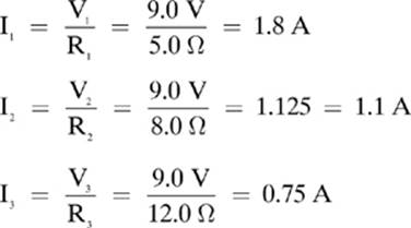
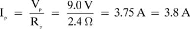
Let”s find the total current in the circuit using two different methods to check our answers.
Ip = I1 + I2 + I3 = 1.8 A + 1.1 A + 0.75 A = 3.7 A
Although not identical, our answers are close enough to confirm that we did the calculations correctly. The differences can be accounted for by the rounding that we have done at each step.
Now we can use the electric power formula to find the power dissipated by each resistor.
P1 = I1 V1 = (1.8)(9.0 V) = 16.2 W = 16 W
P2 = I2 V2 = (1.1)(9.0 V) = 9.9 W
P3 = I3 V3 = (0.75)(9.0 V) = 6.75 W = 6.8 W
Let”s find the total power with two different methods to check our calculations.
Pp = P1 + P2 + P3 = 16 W + 9.9 W + 6.8 W = 32.7 W = 33 W
Pp = Ip Vp = (3.8 A)(9.0 V) = 34 W
Once again, the slight difference in our answers can be attributed to rounding.
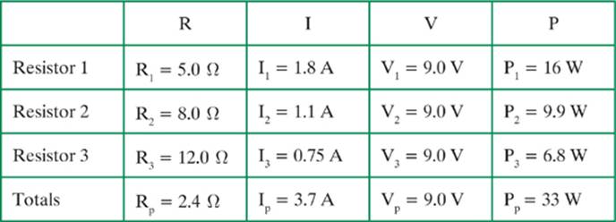
Finally, let”s summarize the results of all of our calculations by filling in our table, as shown here:
In addition to interpreting circuit diagrams, you will want to be able to draw and perhaps even construct them based on specific instructions. A circuit diagram isn”t like a calculation in that there is not a specific answer. There is room for some difference between two different answers. However, certain features are required for each diagram in order to be considered correct. Let”s try an example.
Example 6
Construct a schematic diagram of a battery, a switch, and three bulbs connected in parallel. Arrange the components in such a way that the switch controls all three lights at once.
Solution:
In order to have the switch interrupt the flow of electricity to all three bulbs when it is open, we must put the switch on a pathway between the battery and all three bulbs.
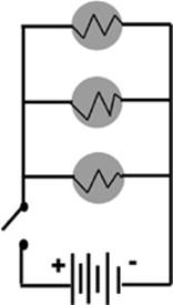
Figure 6.6
Of course, there is room for some differences between individual answers when you are asked to draw schematic diagrams. For example, you may have placed your switch on the left-hand side, rather than the right. There are some aspects of the diagram that must be specific, however. Notice in our diagram, for example, that when the switch is open, none of the bulbs can trace a path back to the right side of the battery.
Before we move on to our review, I will take this opportunity to explain the difference between two of the symbols that appeared in our table of schematic symbols. Many of the components that we normally call batteries, with names such as AAA, D, or C, are actually considered cells. If you look on a AAA cell, you will note that it provides 1.5 V of potential difference. A battery is actually a group of cells arranged in series. If you dissect a 9 V battery, you will find that underneath its metallic coating are six, tiny 1.5 V cells. The 9 V (6 × 1.5 V = 9.0 V!) is the only “true” battery out of the tiny components that most of us call batteries.
Lesson 6–4 Review
1. Three resistors with resistances of 2.0Ω, 5.0Ω, and 9.0Ω, respectively, are connected in a series circuit to a 9.0 V battery. What is the current through the 5.0Ω resistor?
2. A 2.0 µf capacitor is connected in a parallel circuit to a 7.0 µf capacitor. What is the equivalent capacitance?
3. Three resistors with resistances of 12.0Ω, 14.0Ω, and 22.0Ω, respectively, are connected in parallel to a 12.0 V battery. Find the power dissipated by the 14.0Ω resistor.