SAT Physics Subject Test
Chapter 14 Optics
REFLECTION AND REFRACTION
Imagine a beam of light directed toward a smooth transparent surface. When it hits this surface, some of its energy will be reflected off the surface and some will be transmitted into the new medium. We can figure out the directions of the reflected and transmitted beams by calculating the angles that the beams make with the normal to the interface. The normal is a line perpendicular to the interface. In the following figure, an incident beam strikes the boundary of another medium; it could be a beam of light in air striking a piece of glass.
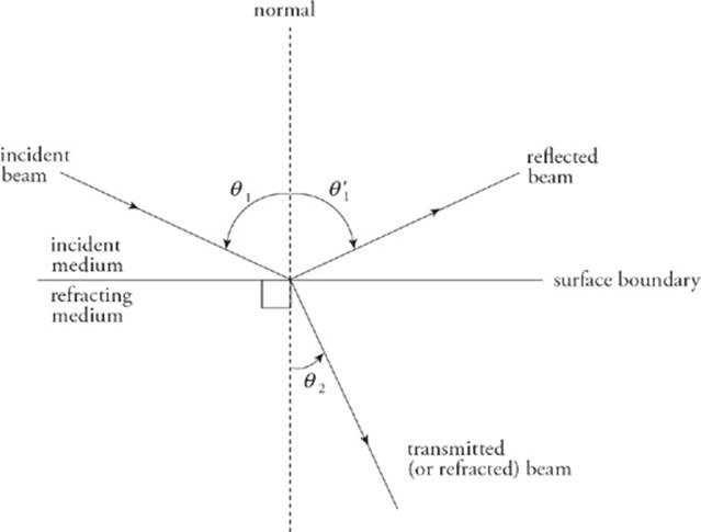
The angle that the incident beam makes with the normal is called the angle of incidence, or θ1. The angle that the reflected beam makes with the normal is called the angle of reflection, θ′1, and the angle that the transmitted beam makes with the normal is called the angle of refraction,θ2. The incident, reflected, and transmitted beams of light all lie in the same plane.
The relationship between θ1 and θ1′ is pretty simple; it is called the law of reflection.
θ1 = θ1′
To describe how θ1 and θ2 are related, we first need to talk about a medium”s index of refraction.
When light travels through empty space (vacuum), its speed is c = 3.00 × 10⁸ m/s; but when a light travels through a material medium (such as water or glass), it”s constantly being absorbed and re-emitted by the atoms of the material and, as a result, its apparent speed, v, is some fraction of c. The reciprocal of this fraction,
n = ![]()
is called the medium”s index of refraction.
For example, since the speed of light in water is v = 2.25 × 10⁸ m/s, the index of refraction of water is
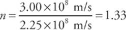
Notice that n has no units; it”s also never less than 1.
The equation that relates θ1 and θ2 involves the index of refraction of the incident medium (n1) and the index of refraction of the refracting medium (n2); it”s called Snell”s law (know this for the test).
n1 sinθ1 = n2 sinθ2
If n2 > n1 (i.e., when the light slows down in n2), then Snell”s law tells us that θ2 < θ1; that is, the beam will bend (refract) toward the normal as it enters the medium. On the contrary, if n2 < n1 (i.e., when the light speeds up in n2), then θ2 > θ1, and the beam will bend away from the normal.
![]()
5. A beam of light in air is incident upon a piece of glass, striking the surface at an angle of 60°. If the index of refraction of the glass is 1.5, what are the angles of reflection and refraction?
Here”s How to Crack It
If the light beam makes an angle of 60° with the surface, then it makes an angle of 30° with the normal; this is the angle of incidence. By the law of reflection, then, the angle of reflection is also 30°. We use Snell”s law to find the angle of refraction. The index of refraction of air is close to 1, so we can say that n = 1 for air.
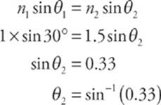
which is about 19°.
Notice that θ2 < θ1, as we would expect, since the refracting medium (glass) has a greater index than the incident medium (air).
![]()
Dispersion of Light
One thing we learned when we studied waves is that wave speed is independent of frequency (Wave Rule #1). For a given medium, different frequencies give rise to different wavelengths because the equation λf = v must always be satisfied and v doesn”t vary. But when light travels through a material medium, it displays dispersion, which is a variation in wave speed with frequency (or wavelength). So, the definition of the index of refraction, n = c/v, should be accompanied by a statement of the frequency of the light used to measure v, since different frequencies have different speeds and different indices. A piece of glass may have the following indices for visible light.
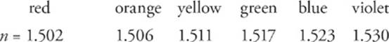
Notice that as the wavelength decreases, the refractive index increases. In general, higher frequency waves have higher indices of refraction. Most lists of refractive index values are tabulated using yellow light of wavelength 589 nm (frequency 5.1 × 10¹⁴ Hz).
Although the variation in the values of the refractive index across the visible spectrum is pretty small, when white light (which is a combination of all the colors of the visible spectrum) hits a glass prism, the beam is split into its component colors.
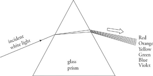
Why? Because each color has its own index. Snell”s law tells us that each color will have its own angle of refraction. Therefore, each color emerges from the prism at a slightly different angle, so the light disperses into its component colors.
Total Internal Reflection
When a beam of light strikes the boundary to a medium that has a lower index of refraction, the beam bends away from the normal. As the angle of incidence increases, the angle of refraction becomes larger. At some point, when the angle of incidence reaches a critical angle, θc, the angle of refraction becomes 90°, which means the refracted beam is directed along the surface.
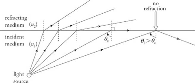
For angles of incidence that are greater than θc, there is no angle of refraction; the entire beam is reflected back into the original medium. This phenomenon is called total internal reflection (sometimes abbreviated TIR).
Total internal reflection occurs when
1) n1 > n2
and
2) θ1 > θc, where θc = sin–1 (n2/n1)
Notice that total internal reflection cannot occur if n1 < n2. If n1 > n2, then total internal reflection is a possibility; it will occur if the angle of incidence is large enough, that is, if it”s greater than the critical angle, θc.
![]()
Questions 6-7
The critical angle for total internal reflection between air and water is known to be 49°.
6. If a beam of light striking an air/water boundary undergoes total internal reflection, will it stay in the air or in the water?
7. Describe what happens if a beam of light in the air strikes the surface of a calm body of water at an angle of 50° to the normal.
Here”s How to Crack It
6. Total internal reflection can occur only if the light is in the medium with the higher index of refraction and strikes a boundary beyond which the index of refraction is lower (and if the angle of incidence is greater than the critical angle). So, if a beam of light striking an air/water boundary experiences total internal reflection, it must have originated (and remain) in the water.
7. The angle of incidence is 50°, which is greater than the critical angle. However, total internal reflection does not occur because the beam is in the air, the medium of lower refractive index. So, the light will experience some reflection (bouncing off the water) and some refraction (bending into the water). The angle of reflection will be the same as the angle of incidence (50°), and the angle of refraction will be smaller than 50° because a beam of light always bends toward the normal when it enters a medium with a greater index of refraction.
![]()
MIRRORS
A mirror is an optical device that forms an image by reflecting light. We”ve all looked into a mirror and seen images of nearby objects. Flat mirrors are called plane mirrors. Let”s begin with a plane mirror; the simplest type of mirror. Then we”ll examine curved mirrors; we”ll have to use geometrical methods or algebraic equations to analyze the patterns of reflection from these.
Plane Mirrors
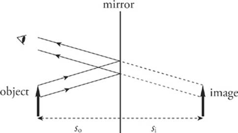
The figure below shows an object (denoted by a bold arrow) in front of a flat mirror. Light that”s reflected off of the object strikes the mirror and is reflected back to our eyes. The directions of the rays reflected off the mirror determines where we perceive the image to be.
There are four questions we”ll answer about the image formed by a mirror.
(1) Where is the image?
(2) Is the image real or is it virtual?
(3) Is the image upright or is it inverted?
(4) What is the height of the image (compared with that of the object)?
When we look at ourselves in a mirror, it seems like our image is behind the mirror, and, if we take a step back, our image also takes a step back. The law of reflection can be used to show that the image seems as far behind the mirror as the object is in front of the mirror. This answers question (1).
An image is said to be real if light rays actually focus at the image. A real image can be projected onto a screen. For a flat mirror, light rays bounce off the front of the mirror; so, of course, no light focuses behind it. Therefore, the images produced by a flat mirror are not real; they arevirtual. This answers question (2).
When we look into a flat mirror, our image isn”t upside down; flat mirrors produce upright images, and question (3) is answered.
Finally, the image formed by a flat mirror is neither magnified nor diminished (minified) relative to the size of the object. This answers question (4).
Spherical Mirrors
A spherical mirror is a mirror that”s curved in such a way that its surface forms part of a sphere.
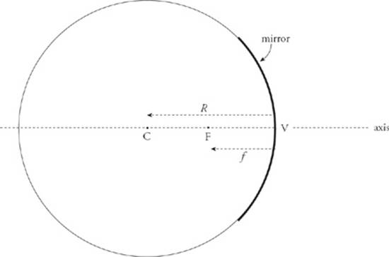
The center of this imaginary sphere is the mirror”s center of curvature, and the radius of the sphere is called the mirror”s radius of curvature, R. Halfway between the mirror and the center of curvature, C, is the focus (or focal point), F. The intersection of the mirror”s optic axis (its axis of symmetry) with the mirror itself is called the vertex, V, and the distance from V to F is called the focal length, f, which is equal to one-half of the radius of curvature.
f = ![]()
If the mirror had a parabolic cross-section, then any ray parallel to the axis would be reflected by the mirror through the focal point. Spherical mirrors do this for incident light rays near the axis (paraxial rays) because in the region of the mirror that”s close to the axis, the shapes of a parabolic mirror and a spherical mirror are nearly identical.
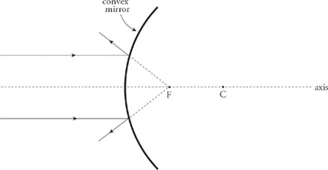
The previous two figures illustrate a concave mirror, a mirror whose reflective side is caved in toward the center of curvature. The following figure illustrates the convex mirror, which has a reflective side that curves away from the center of curvature.
Ray Tracing for Mirrors
One method of answering the four questions we listed earlier involves a geometric approach called ray tracing. Representative rays of light are sketched in a diagram that depicts the object and the mirror; the point at which the reflected rays intersect (or appear to intersect) is the location of the image. Some rules governing rays are below.
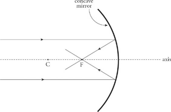
Concave Mirrors
• An incident ray parallel to the axis is reflected through the focus.
• An incident ray that passes through the focus is reflected parallel to the axis.
• An incident ray that strikes the vertex is reflected at an equal angle to the axis.
Convex Mirrors
• An incident ray parallel to the axis is reflected away from the virtual focus.
• An incident ray directed toward the virtual focus is reflected parallel to the axis.
• An incident ray that strikes the vertex is reflected at an equal angle to the axis.
![]()
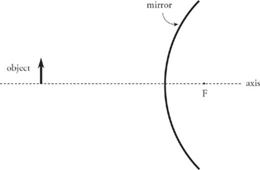
8. The figure below shows a concave mirror and an object (the bold arrow). Use a ray diagram to locate the image of the object.
Here”s How to Crack It
It only takes two distinct rays to locate the image.
![]()
![]()
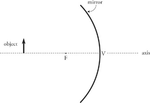
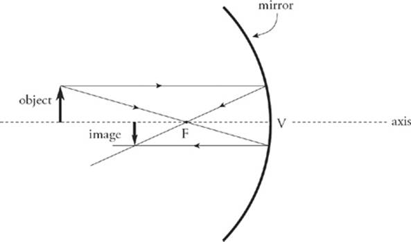
9. The figure below shows a convex mirror and an object (the arrow). Use a ray diagram to locate the image of the object.
Here”s How to Crack It
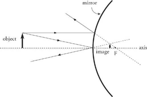
The ray diagrams of the preceding examples can be used to determine the location, orientation, and size of the image. The nature of the image—that is, whether it”s real or virtual—can be determined by seeing on which side of the mirror the image is formed. If the image is formed on the same side of the mirror as the object, then the image is real, but if the image is formed on the opposite side of the mirror, it”s virtual. Therefore, the image in Question 8 is real, and the image in Question 9 is virtual.
![]()
Using Equations to Answer Questions About the Image
The fastest and easiest way to get information about an image is to use two equations and some simple conventions. You should know how to use these two equations for the SAT Physics Subject Test.
The first equation, called the mirror equation, is
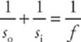
where so is the object”s distance from the mirror, si is the image”s distance from the mirror, and f is the focal length of the mirror.
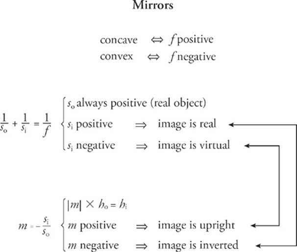
The value of so is always positive for a real object, but si can be positive or negative. The sign of si tells us whether the image is real or virtual: If si is positive, the image is real; and if si is negative, the image is virtual.
The second equation is called the magnification equation
m = – ![]()
This gives the magnification; the height of the image, hi, is |m| times the height of the object, ho. If m is positive, then the image is upright relative to the object; if m is negative, it”s inverted. Because so is always positive, we can come to two conclusions: If si is positive, then m is negative, so real images are always inverted, and, if si is negative, then m is positive, so virtual images are always upright.
Image Is Everything
Remember that all real
images are inverted and
all virtual images are
upright.
Finally, to distinguish mathematically between concave and convex mirrors, we always write the focal length f as a positive value for concave mirrors and a negative value for convex mirrors. With these two equations and their accompanying conventions, all four questions about an image can be answered. The mirror equation answers questions (1) and (2), and the magnification equation answers (3) and (4).
![]()
Questions 10-13
An object of height 4 cm is placed 30 cm in front of a concave mirror whose focal length is 10 cm.
10. Where”s the image?
11. Is it real or virtual?
12. Is it upright or inverted?
13. What”s the height of the image?
Here”s How to Crack It
10. With so = 30 cm and f = 10 cm, the mirror equation gives

The image is located 15 cm in front of the mirror.
11. Because si is positive, the image is real.
12. Real images are inverted.
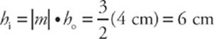
13. The magnification is
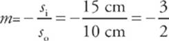
(The fact that the magnification is negative confirms that the image is inverted, as we said in Question 12.) The height of the image is
![]()
Questions 14-17
An object of height 4 cm is placed 20 cm in front of a convex mirror whose focal length is –30 cm.
14. Where”s the image?
15. Is it real or virtual?
16. Is it upright or inverted?
17. What”s the height of the image?
Here”s How to Crack It
14. With so = 20 cm and f = –30 cm, the mirror equation gives us:
![]()
So the image is located 12 cm behind the mirror.
15. Because si is negative, the image is virtual.
16. Virtual images are upright.
17. The magnification is:
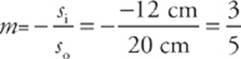
(The fact that the magnification is positive tells us that the image is upright, as we said in Question 17.) The height of the image is
hi = |m| × ho = ![]() (4 cm) = 2.4 cm
(4 cm) = 2.4 cm
![]()
18. Show how the statements made earlier about plane mirrors can be derived from the mirror and magnification equations.
Here”s How to Crack It
A plane mirror can be considered a spherical mirror with an infinite radius of curvature (and an infinite focal length). If f = ∞, then 1/f = 0, and the mirror equation becomes
 = 0 ⇒ si = –so
The image is as far behind the mirror as the object is in front. Also, since so is always positive, si is negative, so the image is virtual. The magnification is
![]()
and the image is upright and has the same height as the object. The mirror and magnification equations confirm our description of images formed by plane mirrors.
What Produces What?
Only concave mirrors can
produce real images
(if s0 ![]() f). Convex mirrors
f). Convex mirrors
and plane mirrors can only
produce virtual images.
![]()
![]()
19. Show why convex mirrors can only form virtual images.
Here”s How to Crack It
Because f is negative and so is positive, the mirror equation

immediately tells us that si cannot be positive (if it were, the left-hand side would be the sum of two positive numbers, while the right-hand side would be negative). Since si must be negative, the image must be virtual.
![]()
![]()
Questions 20-22
An object placed 60 cm in front of a spherical mirror forms a real image at a distance of 30 cm from the mirror.
20. Is the mirror concave or convex?
21. What”s the mirror”s focal length?
22. Is the image taller or shorter than the object?
Here”s How to Crack It
20. The fact that the image is real tells us that the mirror cannot be convex, since convex mirrors form only virtual images. The mirror is concave.
21. With so = 60 cm and si = 30 cm (si is positive since the image is real), the mirror equation tells us that

Notice that f is positive; it must be, since the mirror is concave.
22. The magnification is
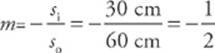
Since the absolute value of m is less than 1, the mirror makes the object look smaller. The image is only half as tall as the object (and is upside down, because m is negative).
![]()
![]()
23. A concave mirror with a focal length of 25 cm is used to create a real image that has twice the height of the object. How far is the image from the mirror?
Here”s How to Crack It
Since hi (the height of the image) is twice ho (the height of the object) the value of the magnification is either +2 or –2. To figure out which, we just notice that the image is real; real images are inverted, so the magnification, m, must be negative. Therefore, m = –2, so
Substituting this into the mirror equation gives us
![]()
![]()