CHEMISTRY THE CENTRAL SCIENCE
12 SOLIDS AND MODERN MATERIALS
12.5 IONIC SOLIDS
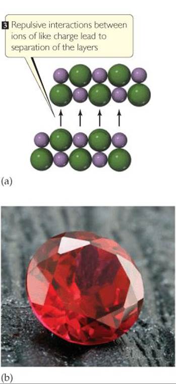
Ionic solids are held together by the electrostatic attraction between cations and anions—ionic bonds. ![]() (Section 8.2) The high melting and boiling points of ionic compounds are a testament to the strength of the ionic bonds. The strength of an ionic bond depends on the charges and sizes of the ions. As discussed in Chapters 8 and 11, the attractions between cations and anions increase as the charges of the ions go up. Thus NaCl, where the ions have charges of 1+ and 1—, melts at 801 °C, whereas MgO, where the ions have charges of 2+ and 2—, melts at 2852 °C. The interactions between cations and anions also increase as the ions get smaller, as we see from the melting points of the alkali metal halides in
(Section 8.2) The high melting and boiling points of ionic compounds are a testament to the strength of the ionic bonds. The strength of an ionic bond depends on the charges and sizes of the ions. As discussed in Chapters 8 and 11, the attractions between cations and anions increase as the charges of the ions go up. Thus NaCl, where the ions have charges of 1+ and 1—, melts at 801 °C, whereas MgO, where the ions have charges of 2+ and 2—, melts at 2852 °C. The interactions between cations and anions also increase as the ions get smaller, as we see from the melting points of the alkali metal halides in ![]() TABLE 12.3. These trends mirror the trends in lattice energy discussed in Section 8.2.
TABLE 12.3. These trends mirror the trends in lattice energy discussed in Section 8.2.
Although ionic and metallic solids both have high melting and boiling points, the differences between ionic and metallic bonding are responsible for important differences in their properties. Because the valence electrons in ionic compounds are confined to the anions, rather than being delocalized, ionic compounds are typically electrical insulators. They tend to be brittle, a property explained by repulsive interactions between ions of like charge. When a stress is applied to an ionic solid, as in ![]() FIGURE 12.25, the planes of atoms, which before the stress were arranged with cations next to anions, shift so that the alignment becomes cation-cation, anion-anion. The resulting repulsive interaction causes the planes to split away from each other. Brittleness is not necessarily a negative quality, of course, as evidenced by the beauty of a cut gemstone. The multiple facets that are the basis of this beauty are possible because crystals cleave along well-defined directions with respect to the crystalline lattice.
FIGURE 12.25, the planes of atoms, which before the stress were arranged with cations next to anions, shift so that the alignment becomes cation-cation, anion-anion. The resulting repulsive interaction causes the planes to split away from each other. Brittleness is not necessarily a negative quality, of course, as evidenced by the beauty of a cut gemstone. The multiple facets that are the basis of this beauty are possible because crystals cleave along well-defined directions with respect to the crystalline lattice.
![]() GO FIGURE
GO FIGURE
Why don't metals cleave in the way depicted here for ionic substances?
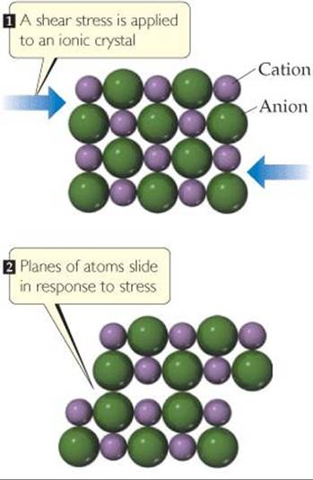
![]() FIGURE 12.25 Brittleness and faceting in ionic crystals. (a) When a shear stress is applied to an ionic solid, the crystal separates along a plane of atoms as shown here. (b) This property of ionic crystals is used to facet gemstones, such as rubies.
FIGURE 12.25 Brittleness and faceting in ionic crystals. (a) When a shear stress is applied to an ionic solid, the crystal separates along a plane of atoms as shown here. (b) This property of ionic crystals is used to facet gemstones, such as rubies.
TABLE 12.3 • Properties of the Alkali Metal Halides
Structures of Ionic Solids
Like metallic solids, ionic solids tend to adopt structures with symmetric, close-packed arrangements of atoms. However, important differences arise because we now have to pack together spheres that have different radii and opposite charges. Because cations are often considerably smaller than anions ![]() (Section 7.3) the coordination numbers in ionic compounds are smaller than those in close-packed metals. Even if the anions and cations were the same size, the close-packed arrangements seen in metals cannot be replicated without letting ions of like charge come in contact with each other. The repulsions between ions of the same type make such arrangements unfavorable. The most favorable structures are those where the cation-anion distances are as close as permitted by ionic radii but the anion-anion and cation-cation distances are maximized.
(Section 7.3) the coordination numbers in ionic compounds are smaller than those in close-packed metals. Even if the anions and cations were the same size, the close-packed arrangements seen in metals cannot be replicated without letting ions of like charge come in contact with each other. The repulsions between ions of the same type make such arrangements unfavorable. The most favorable structures are those where the cation-anion distances are as close as permitted by ionic radii but the anion-anion and cation-cation distances are maximized.
![]() GIVE IT SOME THOUGHT
GIVE IT SOME THOUGHT
Is it possible for all atoms in an ionic compound to lie on the lattice points as they do in the metallic structures shown in Figure 12.11?
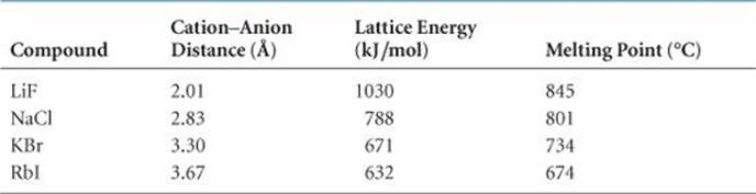
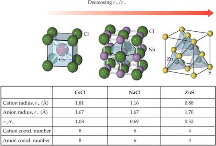
Three common ionic structure types are shown in ![]() FIGURE 12.26. The cesium chloride (CsCl) structure is based on a primitive cubic lattice. Anions sit on the lattice points at the corners of the unit cell, and a cation sits at the center of each cell. (Remember, there is no lattice point inside a primitive unit cell.) With this arrangement, both cations and anions are surrounded by a cube of eight ions of the opposite type.
FIGURE 12.26. The cesium chloride (CsCl) structure is based on a primitive cubic lattice. Anions sit on the lattice points at the corners of the unit cell, and a cation sits at the center of each cell. (Remember, there is no lattice point inside a primitive unit cell.) With this arrangement, both cations and anions are surrounded by a cube of eight ions of the opposite type.
The sodium chloride (NaCl) and zinc blende (ZnS) structures are based on a face-centered cubic lattice. In both structures the anions sit on the lattice points that lie on the corners and faces of the unit cell, but the two-atom motif is slightly different for the two structures. In NaCl the Na+ions are displaced from the Cl– ions along the edge of the unit cell, whereas in ZnS the Zn2+ ions are displaced from the S2– ions along the body diagonal of the unit cell. This difference leads to different coordination numbers. In sodium chloride, each cation and each anion are surrounded by six ions of the opposite type, leading to an octahedral coordination environment. In zinc blende, each cation and each anion are surrounded by four ions of the opposite type, leading to a tetrahedral coordination geometry. The cation coordination environments can be seen in ![]() FIGURE 12.27.
FIGURE 12.27.
![]() GO FIGURE
GO FIGURE
Do the anions touch each other in any of these three structures? If not, which ions do touch each other?
![]() FIGURE 12.26 The structures of CsCl, NaCl, and ZnS. Each structure type can be generated by the combination of a two-atom motif and the appropriate lattice.
FIGURE 12.26 The structures of CsCl, NaCl, and ZnS. Each structure type can be generated by the combination of a two-atom motif and the appropriate lattice.
![]() FIGURE 12.27 Coordination environments in CsCl, NaCl, and ZnS. The sizes of the ions have been reduced to show the coordination environments clearly.
FIGURE 12.27 Coordination environments in CsCl, NaCl, and ZnS. The sizes of the ions have been reduced to show the coordination environments clearly.
For a given ionic compound, we might ask which type of structure is most favorable. There are a number of factors that come into play, but two of the most important are the relative sizes of the ions and the stoichiometry. Consider first ion size. Notice in Figure 12.27 that the coordination number changes from 8 to 6 to 4 on moving from CsCl to NaCl to ZnS. This trend is driven in part by the fact that for these three compounds the ionic radius of the cation gets smaller while the ionic radius of the anion changes very little. When the cation and anion are similar in size, a large coordination number is favored and the CsCl structure is often realized. As the relative size of the cation gets smaller, eventually it is no longer possible to maintain the cation-anion contacts and simultaneously keep the anions from touching each other. When this occurs, the coordination number drops from 8 to 6, and the sodium chloride structure becomes more favorable. As the cation size decreases further, eventually the coordination number must be reduced again, this time from 6 to 4, and the zinc blende structure becomes favored. Remember that, in ionic crystals, ions of opposite charge touch each other but ions of the same charge should not touch.
The relative number of cations and anions also helps determine the most stable structure type. All the structures in Figure 12.27 have equal numbers of cations and anions. These structure types can be realized only for ionic compounds in which the number of cations and anions are equal. When this is not the case, other crystal structures must result. As an example, consider NaF, MgF2, and ScF3 (![]() FIGURE 12.28). Sodium fluoride has the sodium chloride structure with a coordination number of 6 for both cation and anion. Magnesium fluoride has a tetragonal crystal structure called the rutile structure. The cation coordination number is still 6, but the fluoride coordination number is now only 3. In the scandium fluoride structure, the cation coordination number is still 6 but the fluoride coordination number has dropped to 2. As the cation/anion ratio goes down, there are fewer cations to surround each anion, and so the anion coordination number must decrease. We can state this quantitatively with the relationship
FIGURE 12.28). Sodium fluoride has the sodium chloride structure with a coordination number of 6 for both cation and anion. Magnesium fluoride has a tetragonal crystal structure called the rutile structure. The cation coordination number is still 6, but the fluoride coordination number is now only 3. In the scandium fluoride structure, the cation coordination number is still 6 but the fluoride coordination number has dropped to 2. As the cation/anion ratio goes down, there are fewer cations to surround each anion, and so the anion coordination number must decrease. We can state this quantitatively with the relationship

![]() GO FIGURE
GO FIGURE
How many cations are there per unit cell for each of these structures? How many anions per unit cell?
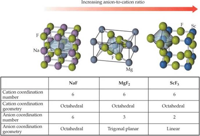
![]() FIGURE 12.28 Coordination numbers depend on stoichiometry. The sizes of the ions have been reduced to show the coordination environments clearly.
FIGURE 12.28 Coordination numbers depend on stoichiometry. The sizes of the ions have been reduced to show the coordination environments clearly.
![]() GIVE IT SOME THOUGHT
GIVE IT SOME THOUGHT
In the crystal structure of potassium oxide, the oxide ions are coordinated by eight potassium ions. What is the coordination number of potassium?
SAMPLE EXERCISE 12.2 Calculating the Empirical Formula and Density of an Ionic Solid
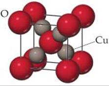
The unit cell of a binary compound of copper and oxygen is shown here. Given this image and the ionic radii rCu+ = 0.74 Å and rO2- = 1.26 Å, (a) determine the empirical formula of this compound, (b) determine the coordination numbers of copper and oxygen, (c) estimate the length of the edge of the cubic unit cell, and (d) estimate the density of the compound.
SOLUTION
Analyze and Plan There are four parts to this problem.
(a) To determine the empirical formula we need to determine how many of each type of ion there are per unit cell.
(b) If we can visually determine the coordination number of one of the ions, we can use Equation 12.1 to determine the coordination number of the other ion.
(c) To estimate the length of the unit cell edge we must first determine the direction along which the ions touch. We can then use ionic radii and trigonometry to estimate the size of the unit cell.
(d) Because density is an intensive property, the density of the unit cell is the same as the density of a bulk crystal. To calculate the density we must divide the mass of the atoms per unit cell by the volume of the unit cell.
Solve
(a) There are four copper ions and one oxygen ion located completely inside the unit cell. In addition there are eight oxygen ions on the corners of the unit cell. Therefore, the number of oxygen ions per unit cell is 1 + 8(1/8) = 2. Given the fact that there are four copper ions and two oxygen ions per unit cell the empirical formula is Cu2O. This is copper(I) oxide.
(b) It is easier to see the coordination environments of atoms within the unit cell because we do not have to visualize the atoms in neighboring unit cells. In this example we see that the oxygen ion at the center of the unit cell is tetrahedrally coordinated by four copper ions. The copper ions appear to have two oxygen neighbors, but we can double check this conclusion using Equation 12.1:

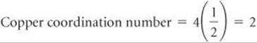
This result matches our expectations from inspection of the picture.
(c) In this structure the ions touch along the body diagonal of the unit cell. This is shown more clearly in the following figure, where the atoms in the front half of the unit cell have been removed for clarity:
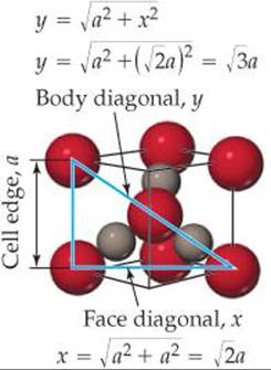
Starting in the lower right-hand corner of the unit cell, the distance from the center of the oxygen ion at the corner of the unit cell to the center of the oxygen at the body center of the unit cell is r(O2–) + 2r(Cu+) + r(O2–) = 2r(O2–) + 2r(Cu+). Twice this distance is equal to the body diagonal,y.
y = 2[2r(Cu+) + 2r(O2–)] = 4[r(Cu+) + r(O2–)] = 4[0.74 Å + 1.26 Å] = 8.00 Å
Using trigonometry and the Pythagorean theorem, it can be shown that the body diagonal of a cube is ![]() times longer than the edge of the cube, a. We can use this relationship to determine the edge length of the unit cell:
times longer than the edge of the cube, a. We can use this relationship to determine the edge length of the unit cell:
![]()
(d) Because we now know the number of atoms per unit cell and the size of the unit cell, we are in a position to calculate the density from the atomic weights of copper (65.55 amu) and oxygen (16.00 amu) and the appropriate conversions:
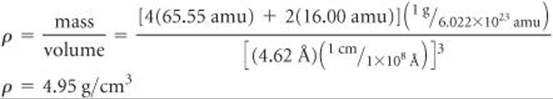
Check Copper is often found in the +1 oxidation state, so Cu2O is a realistic empirical formula. The densities of most solids fall between the density of lithium (0.5g/cm3) and that of iridium (22.6 g/cm3), so this value is reasonable.
PRACTICE EXERCISE
Estimate the length of the cubic unit cell edge and the density of CsCl (Figure 12.26) from the ionic radii of cesium, 1.81 Å, and chloride, 1.67 Å.
Answer: a = 4.02Å and ρ = 4.31g/cm3