CHEMISTRY THE CENTRAL SCIENCE
23 TRANSITION METALS AND COORDINATION CHEMISTRY
23.6 CRYSTAL-FIELD THEORY
Scientists have long recognized that many of the magnetic properties and colors of transition-metal complexes are related to the presence of d electrons in the metal cation. In this section we consider a model for bonding in transition-metal complexes, crystal-field theory, that accounts for many of the observed properties of these substances.* Because the predictions of crystal-field theory are essentially the same as those obtained with more advanced molecular-orbital theories, crystal-field theory is an excellent place to start in considering the electronic structure of coordination compounds.
The ability of a metal ion to attract ligands is a Lewis acid-base interaction, in which the base—that is, the ligand—donates a pair of electrons to an empty orbital on the metal ion (![]() FIGURE 23.27). Much of the attractive interaction between the metal ion and the ligands is due, however, to the electrostatic forces between the positive charge on the metal ion and negative charges on the ligands. If the ligand is ionic, as in the case of Cl– or SCN–, the electrostatic interaction is the usual cation–anion attraction. When the ligand is a neutral molecule, as in the case of H2O or NH3, the negative ends of these polar molecules, which contain an unshared electron pair, are directed toward the metal ion. In this case, the attractive interaction is of the ion–dipole type.
FIGURE 23.27). Much of the attractive interaction between the metal ion and the ligands is due, however, to the electrostatic forces between the positive charge on the metal ion and negative charges on the ligands. If the ligand is ionic, as in the case of Cl– or SCN–, the electrostatic interaction is the usual cation–anion attraction. When the ligand is a neutral molecule, as in the case of H2O or NH3, the negative ends of these polar molecules, which contain an unshared electron pair, are directed toward the metal ion. In this case, the attractive interaction is of the ion–dipole type. ![]() (Section 11.2) In either case, the ligands are attracted strongly toward the metal ion. Because of the metal–ligand electrostatic attraction, the energy of the complex is lower than the combined energy of the separated metal ion and ligands.
(Section 11.2) In either case, the ligands are attracted strongly toward the metal ion. Because of the metal–ligand electrostatic attraction, the energy of the complex is lower than the combined energy of the separated metal ion and ligands.
Although the metal ion is attracted to the ligand electrons, the metal ion's d electrons are repulsed by the ligands. Let's examine this effect more closely, specifically the case in which the ligands form an octahedral array around a metal ion that has coordination number 6.
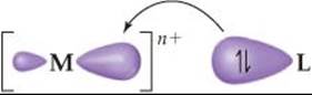
![]() FIGURE 23.27 Metal-ligand bond formation. The ligand acts as a Lewis base by donating its nonbonding electron pair to a hybrid orbital on the metal ion. The bond that results is strongly polar with some covalent character.
FIGURE 23.27 Metal-ligand bond formation. The ligand acts as a Lewis base by donating its nonbonding electron pair to a hybrid orbital on the metal ion. The bond that results is strongly polar with some covalent character.
![]() GO FIGURE
GO FIGURE
Which d orbitals have lobes that point directly toward the ligands in an octahedral crystal field?
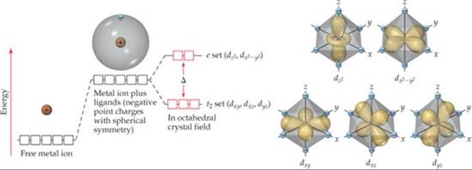
![]() FIGURE 23.28 Energies of d orbitals in a free metal ion, a spherically symmetric crystal field, and an octahedral crystal field.
FIGURE 23.28 Energies of d orbitals in a free metal ion, a spherically symmetric crystal field, and an octahedral crystal field.
In crystal-field theory, we consider the ligands to be negative points of charge that repel the electrons in the d orbitals of the metal ion. The energy diagram in ![]() FIGURE 23.28 shows how these ligand point charges affect the energies of the d orbitals. First we imagine the complex as having all the ligand point charges uniformly distributed on the surface of a sphere centered on the metal ion. The average energy of the metal ion's d orbitals is raised by the presence of this uniformly charged sphere. Hence, the energies of all five d orbitals are raised by the same amount.
FIGURE 23.28 shows how these ligand point charges affect the energies of the d orbitals. First we imagine the complex as having all the ligand point charges uniformly distributed on the surface of a sphere centered on the metal ion. The average energy of the metal ion's d orbitals is raised by the presence of this uniformly charged sphere. Hence, the energies of all five d orbitals are raised by the same amount.
This energy picture is only a first approximation, however, because the ligands are not distributed uniformly on a spherical surface and, therefore, do not approach the metal ion equally from every direction. Instead, we envision the six ligands approaching along x-, y-, and z-axes, as shown on the right in Figure 23.28. This arrangement of ligands is called an octahedral crystal field. Because the metal ion's d orbitals have different orientations and shapes, they do not all experience the same repulsion from the ligands and, therefore, do not all have the same energy under the influence of the octahedral crystal field. To see why, we must consider the shapes of the d orbitals and how their lobes are oriented relative to the ligands.
Figure 23.28 shows that the lobes of the dz2 and dx2–y2 orbitals are directed along the x-, y-, and z-axes and so point directly toward the ligand point charges. In the dxy, dxz, and dyz orbitals, however, the lobes are directed between the axes and so do not point directly toward the charges. The result of this difference in orientation—dx2–y2 and dz2 lobes point directly toward the ligand charges; dxy, dxz, and dyz lobes do not—is that the energy of the dx2–y2 and dz2 orbitals is higher than the energy of the dxy, dxz, and dyz orbitals. This difference in energy is represented by the red boxes in the energy diagram of Figure 23.28.
It might seem like the energy of the dx2–y2 orbital should be different from that of the dz2 orbital because the dx2–y2 has four lobes pointing at ligands and the dz2 has only two lobes pointing at ligands. However, the dz2 orbital does have electron density in the xy plane, represented by the ring encircling the point where the two lobes meet. More advanced calculations show that two orbitals do indeed have the same energy in the presence of the octahedral crystal field.
Because their lobes point directly at the negative ligand charges, electrons in the metal ion's dz2 and dx2–y2 orbitals experience stronger repulsions than those in the dxy, dxz, and dyz orbitals. As a result, the energy splitting shown in Figure 23.28 occurs. The three lower-energy d orbitals are called the t2 set of orbitals, and the two higher-energy ones are called the e set.* The energy gap Δ between the two sets is often called the crystal-field splitting energy.
Crystal-field theory helps us account for the colors observed in transition-metal complexes. The energy gap Δ between the e and t2 sets of d orbitals is of the same order of magnitude as the energy of a photon of visible light. It is therefore possible for a transition-metal complex to absorb visible light that excites an electron from a lower-energy (t2) d orbital into a higher-energy (e) one. In [Ti(H2O)6]3+, for example, the Ti(III) ion has an [Ar]3d1 electron configuration. (Recall from Section 7.4 that when determining the electron configurations of transition-metal ions, we remove the s electrons first.) Ti(III) is thus called a d1 ion. In the ground state of [Ti(H2O)6]3+, the single 3d electron resides in an orbital in the t2 set (![]() FIGURE 23.29). Absorption of 495-nm light excites this electron up to an orbital in the e set, generating the absorption spectrum shown in Figure 23.26. Because this transition involves exciting an electron from one set of d orbitals to the other, we call it a d-d transition. As noted earlier, the absorption of visible radiation that produces this d-d transition causes the [Ti(H2O)6]3+ ion to appear red-violet.
FIGURE 23.29). Absorption of 495-nm light excites this electron up to an orbital in the e set, generating the absorption spectrum shown in Figure 23.26. Because this transition involves exciting an electron from one set of d orbitals to the other, we call it a d-d transition. As noted earlier, the absorption of visible radiation that produces this d-d transition causes the [Ti(H2O)6]3+ ion to appear red-violet.
![]() GO FIGURE
GO FIGURE
How would you calculate the energy gap between the t2 and e orbitals from this diagram?
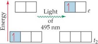
![]() FIGURE 23.29 The d-d transition in [Ti(H2O)6]3+ is produced by the absorption of 495-nm light.
FIGURE 23.29 The d-d transition in [Ti(H2O)6]3+ is produced by the absorption of 495-nm light.
![]() GIVE IT SOME THOUGHT
GIVE IT SOME THOUGHT
Why are compounds of Ti(IV) colorless?
The magnitude of the crystal-field splitting energy and, consequently, the color of a complex depend on both the metal and the ligands. For example, [Fe(H2O)6]3+ is light violet, [Cr(H2O)6]3+ is a deeper violet, and [Cr(NH3)6]3+ is yellow. In a ranking called the spectrochemical series, ligands are arranged in order of their abilities to increase splitting energy, as in this abbreviated list:
![]()
The magnitude of Δ increases by roughly a factor of 2 from the far left to the far right of the spectrochemical series. Ligands at the low-Δ end of the spectrochemical series are termed weak-field ligands; those at the high-Δ end are termed strong-field ligands.
![]() FIGURE 23.30 shows what happens to crystal-field splitting when the ligand is varied in a series of chromium(III) complexes. Because the Cr atom has an [Ar]3d54s1 electron configuration, Cr3+ has the configuration [Ar]3d3 and therefore is a d3 ion. Consistent with Hund's rule, the three 3d electrons occupy the t2 set of orbitals, with one electron in each orbital and all the spins the same.
FIGURE 23.30 shows what happens to crystal-field splitting when the ligand is varied in a series of chromium(III) complexes. Because the Cr atom has an [Ar]3d54s1 electron configuration, Cr3+ has the configuration [Ar]3d3 and therefore is a d3 ion. Consistent with Hund's rule, the three 3d electrons occupy the t2 set of orbitals, with one electron in each orbital and all the spins the same. ![]() (Section 6.8) As the crystal field exerted by the six ligands increases, Δ increases. Because the absorption spectrum is related to this energy separation, these complexes vary in color.
(Section 6.8) As the crystal field exerted by the six ligands increases, Δ increases. Because the absorption spectrum is related to this energy separation, these complexes vary in color.
![]() GO FIGURE
GO FIGURE
If you were told to add a colorless Cr(III) complex to this diagram, what would you draw and where would you place it?
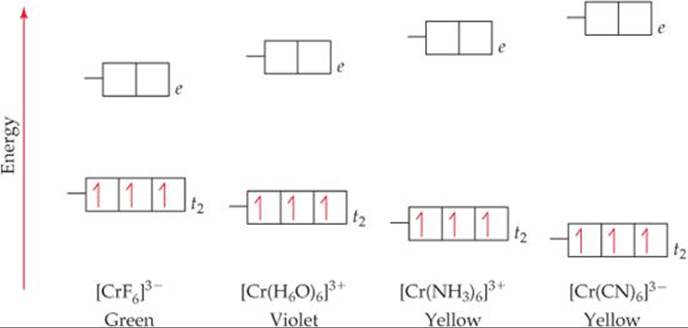
![]() FIGURE 23.30 Effect of ligand on crystal-field splitting. The greater the crystal-field strength of the ligand, the greater the energy gap Δ it causes between the t2 and e sets of the metal ion's d orbitals.
FIGURE 23.30 Effect of ligand on crystal-field splitting. The greater the crystal-field strength of the ligand, the greater the energy gap Δ it causes between the t2 and e sets of the metal ion's d orbitals.
SAMPLE EXERCISE 23.8 Using the Spectrochemical Series
[Ti(H2O)6]3+, [Ti(en)3]3+, and [TiCl6]3– all absorb visible light. Which one absorbs at the shortest wavelength?
SOLUTION
Analyze We are given three octahedral complexes, each containing Ti in the +3 oxidation state. We need to predict which complex absorbs the shortest wavelength of visible light.
Plan Ti(III) is a d1 ion, so we anticipate that the absorption is due to a d-d transition in which the 3d electron is excited from a t2 orbital to an e orbital. The wavelength of the light absorbed is determined by the magnitude of the crystal-field splitting energy, Δ. Thus, we use the position of the ligands in the spectrochemical series to predict the relative values of Δ. The larger the splitting energy, the shorter the wavelength.
Solve Of these three ligands, ethylenediamine (en) is highest in the spectrochemical series and therefore causes the largest split between the t2 and e orbitals. The larger the split, the shorter the wavelength of the light absorbed. Thus, the complex that absorbs the shortest-wavelength light is [Ti(en)3]3+.
PRACTICE EXERCISE
The absorption spectrum of a Ti(III) complex containing the ligand L, [TiL6]3–, shows a peak maximum at a wavelength intermediate between the wavelengths of the absorption maxima for [TiCl6]3– and [TiF6]3–. What can we conclude about the place of L in the spectrochemical series?
Answer: It lies between Cl– and F–.
Electron Configurations in Octahedral Complexes
Crystal-field theory helps us understand the magnetic properties and some important chemical properties of transition-metal ions. From Hund's rule, we expect electrons to always occupy the lowest-energy vacant orbitals first and to occupy a set of degenerate (same-energy) orbitals one at a time with their spins parallel. ![]() (Section 6.8) Thus, if we have a d1, d2, or d3 octahedral complex, the electrons go into the lower-energy t2 orbitals, with their spins parallel. When a fourth electron must be added, we have the two choices shown in
(Section 6.8) Thus, if we have a d1, d2, or d3 octahedral complex, the electrons go into the lower-energy t2 orbitals, with their spins parallel. When a fourth electron must be added, we have the two choices shown in ![]() FIGURE 23.31: The electron can either go into an e orbital, where it will be the sole electron in the orbital, or become the second electron in a t2 orbital. Because the energy difference between the t2 and e sets is the splitting energy Δ, the energy cost of going into an e orbital rather than a t2 orbital is also Δ. Thus, the goal of filling lowest-energy available orbitals first is met by putting the electron in a t2 orbital.
FIGURE 23.31: The electron can either go into an e orbital, where it will be the sole electron in the orbital, or become the second electron in a t2 orbital. Because the energy difference between the t2 and e sets is the splitting energy Δ, the energy cost of going into an e orbital rather than a t2 orbital is also Δ. Thus, the goal of filling lowest-energy available orbitals first is met by putting the electron in a t2 orbital.
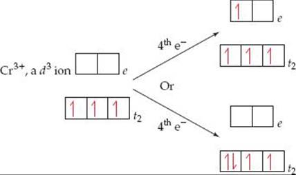
![]() FIGURE 23.31 Two possibilities for adding a fourth electron to a d3 octahedral complex. Whether the fourth electron goes into a t2 orbital or into an e orbital depends on the relative energies of the crystal-field splitting energy and the spin-pairing energy.
FIGURE 23.31 Two possibilities for adding a fourth electron to a d3 octahedral complex. Whether the fourth electron goes into a t2 orbital or into an e orbital depends on the relative energies of the crystal-field splitting energy and the spin-pairing energy.
There is a penalty for doing this, however, because the electron must now be paired with the electron already occupying the orbital. The difference between the energy required to pair an electron in an occupied orbital and the energy required to place that electron in an empty orbital is called the spin-pairing energy. The spin-pairing energy arises from the fact that the electrostatic repulsion between two electrons that share an orbital (and so must have opposite spins) is greater than the repulsion between two electrons that are in different orbitals and have parallel spins.
In coordination complexes, the nature of the ligands and the charge on the metal ion often play major roles in determining which of the two electron arrangements shown in Figure 23.31 is used. In [CoF6]3– and [Co(CN)6]3–, both ligands have a 1– charge. The F– ion, however, is on the low end of the spectrochemical series, so it is a weak-field ligand. The CN– ion is on the high end and so is a strong-field ligand, which means it produces a larger energy gap Δ than the F– ion. The splittings of the d-orbital energies in these two complexes are compared in ![]() FIGURE 23.32.
FIGURE 23.32.
Cobalt(III) has an [Ar]3d6 electron configuration, so both complexes in Figure 23.32 are d6 complexes. Let's imagine that we add these six electrons one at a time to the d orbitals of the [CoF6]3– ion. The first three go into the t2 orbitals with their spins parallel. The fourth electron could pair up in one of the t2 orbitals. The F– ion is a weak-field ligand, however, and so the energy gap Δ between the t2 set and the e set is small. In this case, the more stable arrangement is the fourth electron in one of the e orbitals. By the same energy argument, the fifth electron goes into the other e orbital. With all five d or-bitals containing one electron, the sixth must pair up, and the energy needed to pair with a t2 electron is less than that needed to pair with an e electron. We end up with four t2 electrons and two e electrons.
Figure 23.32 shows that the crystal-field splitting energy Δ is much larger in the [Co(CN)6]3– complex. In this case, the spin-pairing energy is smaller than Δ, so the lowest-energy arrangement is the six electrons paired in the t2 orbitals.
The [CoF6]3– complex is a high-spin complex; that is, the electrons are arranged so that they remain unpaired as much as possible. The [Co(CN)6]3– ion is a low-spin complex; that is, the electrons are arranged so that they remain paired as much as possible while still following Hund's rule. These two electronic arrangements can be readily distinguished by measuring the magnetic properties of the complex. Experiments show that [CoF6]3– has four unpaired electrons and [Co(CN)6]3– has none. The absorption spectrum also shows peaks corresponding to the different values of Δ in these two complexes.
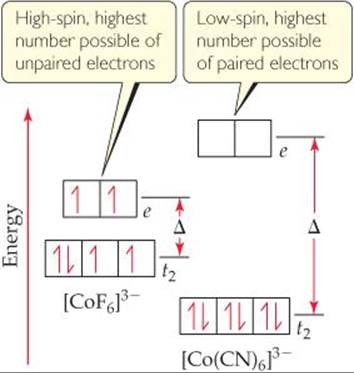
![]() FIGURE 23.32 High-spin and low-spin complexes. The high-spin [CoF6]3– ion has a weak-field ligand and so a small Δ value. The spin-pairing energy required to pair electrons in the t2 orbitals is greater than the e-t2 gap energy Δ. Therefore, filling e orbitals before any electrons are paired in t2 orbitals is the lower-energy state. The low-spin [Co(CN)6]3– ion has a strong-field ligand and so a large Δ value. Here the spin-pairing energy is less than Δ, making three sets of t2-paired electrons the lower-energy state.
FIGURE 23.32 High-spin and low-spin complexes. The high-spin [CoF6]3– ion has a weak-field ligand and so a small Δ value. The spin-pairing energy required to pair electrons in the t2 orbitals is greater than the e-t2 gap energy Δ. Therefore, filling e orbitals before any electrons are paired in t2 orbitals is the lower-energy state. The low-spin [Co(CN)6]3– ion has a strong-field ligand and so a large Δ value. Here the spin-pairing energy is less than Δ, making three sets of t2-paired electrons the lower-energy state.
![]() GIVE IT SOME THOUGHT
GIVE IT SOME THOUGHT
Are strong-field ligands more likely to lead to a high-spin complex or a low-spin complex?
In the transition metal ions of periods 5 and 6 (which have 4d and 5d valence electrons), the d orbitals are larger than in the period 4 ions (which have only 3d electrons). Thus, ions from periods 5 and 6 interact more strongly with ligands, resulting in a larger crystal-field splitting. Consequently, metal ions in periods 5 and 6 are invariably low spin in an octahedral crystal field.
SAMPLE EXERCISE 23.9 Predicting the Number of Unpaired Electrons in an Octahedral Complex
Predict the number of unpaired electrons in high-spin and low-spin Fe3+ complexes that have a coordination number of 6.
SOLUTION
Analyze We must determine how many unpaired electrons there are in the high-spin and low-spin complexes of Fe3+.
Plan We need to consider how the electrons populate the d orbitals in Fe3+ when the metal is in an octahedral complex. There are two possibilities: one giving a high-spin complex and the other giving a low-spin complex. The electron configuration of Fe3+ gives us the number of d electrons. We then determine how these electrons populate the t2 and e sets of d orbitals. In the high-spin case, the energy difference between the t2 and e orbitals is small, and the complex has the maximum number of unpaired electrons. In the low-spin case, the energy difference between the t2 and eorbitals is large, causing the t2 orbitals to be filled before any electrons occupy the e orbitals.
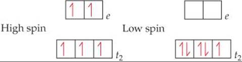
Solve Fe3+ is a d5 ion. In a high-spin complex, all five electrons are unpaired, with three in the t2 orbitals and two in the e orbitals. In a low-spin complex, all five electrons reside in the t2 set, so there is one unpaired electron:
PRACTICE EXERCISE
In octahedral complexes, for which d electron configurations is it possible to distinguish between high-spin and low-spin arrangements?
Answer: d4, d5, d6, d7
Tetrahedral and Square-Planar Complexes
Thus far we have considered crystal-field theory only for complexes having an octahedral geometry. When there are only four ligands in a complex, the geometry is generally tetra-hedral, except for the special case of d8 metal ions, which we will discuss in a moment.
The crystal-field splitting of d orbitals in tetrahedral complexes differs from that in octahedral complexes. Four equivalent ligands can interact with a central metal ion most effectively by approaching along the vertices of a tetrahedron. It turns out—and this is not easy to explain in just a few sentences—that when d orbitals split in a tetrahedral crystal, the three t2 orbitals are raised in energy above the two e orbitals(![]() FIGURE 23.33). Because there are only four ligands instead of six, as in the octahedral case, the crystal-field splitting energy Δ is much smaller for tetrahedral complexes. Calculations show that for the same metal ion and ligand set, Δ for the tetrahedral complex is only four-ninths as large as for the octahedral complex. For this reason, all tetrahedral complexes are high spin; the crystal-field splitting energy is never large enough to overcome the spin-pairing energies.
FIGURE 23.33). Because there are only four ligands instead of six, as in the octahedral case, the crystal-field splitting energy Δ is much smaller for tetrahedral complexes. Calculations show that for the same metal ion and ligand set, Δ for the tetrahedral complex is only four-ninths as large as for the octahedral complex. For this reason, all tetrahedral complexes are high spin; the crystal-field splitting energy is never large enough to overcome the spin-pairing energies.
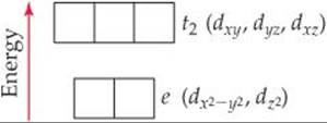
![]() FIGURE 23.33 Energies of the d orbitals in a tetrahedral crystal field. The t2 set is the higher-energy set. Compare the relative e and t2 energy levels here with those in Figure 23.28 for an octahedral crystal field.
FIGURE 23.33 Energies of the d orbitals in a tetrahedral crystal field. The t2 set is the higher-energy set. Compare the relative e and t2 energy levels here with those in Figure 23.28 for an octahedral crystal field.
In a square-planar complex, four ligands are arranged about the metal ion such that all five species are in the xy plane. The resulting energy levels of the d orbitals are illustrated in ![]() FIGURE 23.34. Note in particular that the dz2 orbital is considerably lower in energy than the dx2–y2orbital. To understand why this is so, recall from Figure 23.28 that in an octahedral field the dz2 orbital of the metal ion interacts with the ligands positioned above and below the xy plane. There are no ligands in these two positions in a square-planar complex, which means that the dj2 orbital experiences no repulsive force and so remains in a lower-energy, more stable state.
FIGURE 23.34. Note in particular that the dz2 orbital is considerably lower in energy than the dx2–y2orbital. To understand why this is so, recall from Figure 23.28 that in an octahedral field the dz2 orbital of the metal ion interacts with the ligands positioned above and below the xy plane. There are no ligands in these two positions in a square-planar complex, which means that the dj2 orbital experiences no repulsive force and so remains in a lower-energy, more stable state.
![]() GO FIGURE
GO FIGURE
Why is the dx2-y2 orbital the highest-energy orbital in the square-planar crystal field?
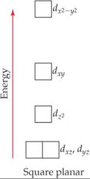
![]() FIGURE 23.34 Energies of the d orbitals in a square-planar crystal field.
FIGURE 23.34 Energies of the d orbitals in a square-planar crystal field.
Square-planar complexes are characteristic of metal ions with a d8 electron configuration. They are nearly always low spin, with the eight d electrons spin-paired to form a diamagnetic complex. This pairing leaves the dx2–y2 orbital empty. Such an electronic arrangement is particularly common among the ions of heavier metals, such as Pd2+, Pt2+, Ir+, and Au3+.
![]() GIVE IT SOME THOUGHT
GIVE IT SOME THOUGHT
Why is the energy of the dxz and dyz orbitals in a square-planar complex lower than that of the dxy orbital?
SAMPLE EXERCISE 23.10 Populating d Orbitals in Tetrahedral and Square-Planar Complexes
Nickel(II) complexes in which the metal coordination number is 4 can have either square-planar or tetrahedral geometry. [NiCl4]2– is paramagnetic, and [Ni(CN)4]2– is diamagnetic. One of these complexes is square planar, and the other is tetrahedral. Use the relevant crystal-field splitting diagrams in the text to determine which complex has which geometry.
SOLUTION
Analyze We are given two complexes containing Ni2+ and their magnetic properties. We are given two molecular geometry choices and asked to use crystal-field splitting diagrams from the text to determine which complex has which geometry.
Plan We need to determine the number of d electrons in Ni2+ and then use Figure 23.33 for the tetrahedral complex and Figure 23.34 for the square-planar complex.
Solve Nickel(II) has the electron configuration [Ar]3d8. Tetrahedral complexes are always high spin, and square-planar complexes are almost always low spin. Therefore, the population of the d electrons in the two geometries is
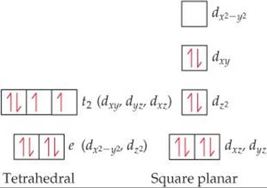
The tetrahedral complex has two unpaired electrons, and the square-planar complex has none. We know from Section 23.1 that the tetrahedral complex must be paramagnetic and the square planar must be diamagnetic. Therefore, [NiCl4]2– is tetrahedral, and [Ni(CN)4]2– is square planar.
Comment Nickel(II) forms octahedral complexes more frequently than square-planar ones, whereas heavier d8 metals tend to favor square-planar coordination.
PRACTICE EXERCISE
How many unpaired electrons do you predict for the tetrahedral [CoCl4]2– ion?
Answer: three
Crystal-field theory can be used to explain many observations in addition to those we have discussed. The theory is based on electrostatic interactions between ions and atoms, which essentially means ionic bonds. Many lines of evidence show, however, that the bonding in complexes must have some covalent character. Therefore, molecular-orbital theory ![]() (Sections 9.7 and 9.8) can also be used to describe the bonding in complexes, although the application of molecular-orbital theory to coordination compounds is beyond the scope of our discussion. Crystal-field theory, although not entirely accurate in all details, provides an adequate and useful first description of the electronic structure of complexes.
(Sections 9.7 and 9.8) can also be used to describe the bonding in complexes, although the application of molecular-orbital theory to coordination compounds is beyond the scope of our discussion. Crystal-field theory, although not entirely accurate in all details, provides an adequate and useful first description of the electronic structure of complexes.
 A CLOSER LOOK
CHARGE-TRANSFER COLOR
In the laboratory portion of your course, you have probably seen many colorful transition-metal compounds, including those shown in ![]() FIGURE 23.35. Many of these compounds are colored because of d-d transitions. Some colored complexes, however, including the violet permanganate ion, MnO4–, and the yellow chromate ion, CrO42–, derive their color from a different type of excitation involving the d orbitals.
FIGURE 23.35. Many of these compounds are colored because of d-d transitions. Some colored complexes, however, including the violet permanganate ion, MnO4–, and the yellow chromate ion, CrO42–, derive their color from a different type of excitation involving the d orbitals.
The permanganate ion strongly absorbs visible light, with a maximum absorption at 565 nm. Because violet is complementary to yellow, this strong absorption in the yellow portion of the visible spectrum is responsible for the violet color of salts and solutions of the ion. What is happening during this absorption of light? The MnO4– ion is a complex of Mn(VII). Because Mn(VII) has a d0 electron configuration, the absorption cannot be due to a d-d transition because there are no d electrons to excite! That does not mean, however, that the d orbitals are not involved in the transition. The excitation in the MnO4– ion is due to a charge-transfer transition, in which an electron on one oxygen lig-and is excited into a vacant d orbital on the Mn ion (![]() FIGURE 23.36). In essence, an electron is transferred from a ligand to the metal, so this transition is called aligand-to-metal charge-transfer (LMCT) transition.
FIGURE 23.36). In essence, an electron is transferred from a ligand to the metal, so this transition is called aligand-to-metal charge-transfer (LMCT) transition.
An LMCT transition is also responsible for the color of the CrO42–, which is a d0 Cr(VI) complex.
Also shown in Figure 23.35 is a salt of the perchlorate ion (ClO4–). Like MnO4–, ClO4– is tetrahedral and has its central atom in the +7 oxidation state. However, because the Cl atom does not have low-lying d orbitals, exciting a Cl electron requires a more energetic photon than does MnO4–. The first absorption for ClO4– is in the ultraviolet portion of the spectrum, so all the visible light is transmitted and the salt appears white.
Other complexes exhibit charge-transfer excitations in which an electron from the metal atom is excited to an empty orbital on a ligand. Such an excitation is called a metal-to-ligand charge-transfer (MLCT) transition.
Charge-transfer transitions are generally more intense than d-d transitions. Many metal-containing pigments used for oil painting, such as cadmium yellow (CdS), chrome yellow (PbCrO4), and red ochre (Fe2O3), have intense colors because of charge-transfer transitions.
RELATED EXERCISES: 23.82, 23.83
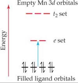
![]() FIGURE 23.36 Ligand-to-metal charge-transfer transition in MnO4–. As shown by the blue arrow, an electron is excited from a nonbonding pair on O into one of the empty d orbitals on Mn.
FIGURE 23.36 Ligand-to-metal charge-transfer transition in MnO4–. As shown by the blue arrow, an electron is excited from a nonbonding pair on O into one of the empty d orbitals on Mn.
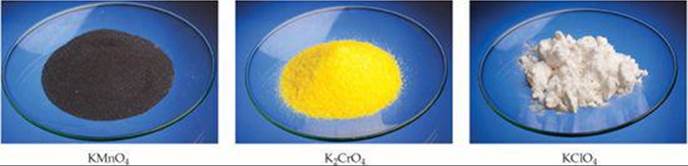
![]() FIGURE 23.35 The colors of compounds can arise from charge-transfer transitions. KMnO4 and K2CrO4 are colored due to ligand-to-metal charge-transfer transitions in their anions. KClO4's anion has no occupied d orbitals and its charge-transfer transition is at higher energy, corresponding to ultraviolet absorption; therefore it appears white.
FIGURE 23.35 The colors of compounds can arise from charge-transfer transitions. KMnO4 and K2CrO4 are colored due to ligand-to-metal charge-transfer transitions in their anions. KClO4's anion has no occupied d orbitals and its charge-transfer transition is at higher energy, corresponding to ultraviolet absorption; therefore it appears white.
SAMPLE INTEGRATIVE EXERCISE Putting Concepts Together
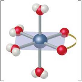
The oxalate ion has the Lewis structure shown in Table 23.4. (a) Show the geometry of the complex formed when this ion complexes with cobalt(II) to form [Co(C2O4)(H2O)4]. (b) Write the formula for the salt formed when three oxalate ions complex with Co(II), assuming that the charge-balancing cation is Na+. (c) Sketch all the possible geometric isomers for the cobalt complex formed in part (b). Are any of these isomers chiral? Explain. (d) The equilibrium constant for the formation of the cobalt(II) complex produced by coordination of three oxalate anions, as in part (b), is 5.0 × 10⁹, and the equilibrium constant for formation of the cobalt(II) complex with three molecules of ortho-phenanthroline (Table 23.4) is 9 × 10¹⁹. From these results, what conclusions can you draw regarding the relative Lewis base properties of the two ligands toward cobalt(II)? (e)Using the approach described in Sample Exercise 17.14, calculate the concentration of free aqueous Co(II) ion in a solution initially containing 0.040 M oxalate (aq) and 0.0010 M Co2+(aq).
SOLUTION
(a) The complex formed by coordination of one oxalate ion is octahedral:
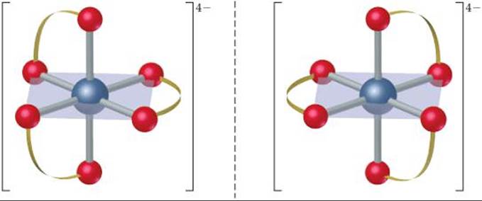
(b) Because the oxalate ion has a charge of 2–, the net charge of a complex with three oxalate anions and one Co2+ ion is 4–. Therefore, the coordination compound has the formula Na4[Co(C2O4)3].
(c) There is only one geometric isomer. The complex is chiral, however, in the same way the [Co(en)3]3+ complex is chiral (Figure 23.22). The two mirror images are not superimposable, so there are two enantiomers:
(d) The ortho-phenanthroline ligand is bidentate, like the oxalate ligand, so they both exhibit the chelate effect. Thus, we conclude that ortho-phenanthroline is a stronger Lewis base toward Co2+ than oxalate. This conclusion is consistent with what we learned about bases in Section 16.7, that nitrogen bases are generally stronger than oxygen bases. (Recall, for example, that NH3 is a stronger base than H2O.)
(e) The equilibrium we must consider involves 3 mol of oxalate ion (represented as Ox2–).
![]()
The formation-constant expression is
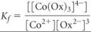
Because Kf is so large, we can assume that essentially all the Co2+ is converted to the oxalato complex. Under that assumption, the final concentration of [Co(Ox)3]4– is 0.0010 M and that of oxalate ion is [Ox2–] = (0.040) – 3(0.0010) = 0.037 M (three Ox2– ions react with each Co2+ ion). We then have
[Co2+] = xM, [Ox2–] ≅ 0.037 M, [[Co(Ox)3]4–] ≅ 0.0010 M
Inserting these values into the equilibrium-constant expression, we have
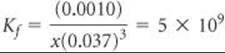
Solving for x, we obtain 4 × 10⁻⁹M. From this, we see that the oxalate has complexed all but a tiny fraction of the Co2+ in solution.