CHEMISTRY THE CENTRAL SCIENCE
9 MOLECULAR GEOMETRY AND BONDING THEORIES
9.8 PERIOD 2 DIATOMIC MOLECULES
In considering the MO description of diatomic molecules other than H2, we will initially restrict our discussion to homonuclear diatomic molecules (those composed of two identical atoms) of period 2 elements.
Period 2 atoms have valence 2s and 2p orbitals, and we need to consider how they interact to form MOs. The following rules summarize some of the guiding principles for the formation of MOs and for how they are populated by electrons:
1. The number of MOs formed equals the number of atomic orbitals combined.
2. Atomic orbitals combine most effectively with other atomic orbitals of similar energy.
3. The effectiveness with which two atomic orbitals combine is proportional to their overlap. That is, as the overlap increases, the energy of the bonding MO is lowered and the energy of the antibonding MO is raised.
4. Each MO can accommodate, at most, two electrons, with their spins paired (Pauli exclusion principle). ![]() (Section 6.7)
(Section 6.7)
5. When MOs of the same energy are populated, one electron enters each orbital (with the same spin) before spin pairing occurs (Hund's rule). ![]() (Section 6.8)
(Section 6.8)
Molecular Orbitals for Li2 and Be2
Lithium has the electron configuration 1s22s1. When lithium metal is heated above its boiling point (1342 °C), Li2 molecules are found in the vapor phase. The Lewis structure for Li2 indicates a Li—Li single bond. We will now use MOs to describe the bonding in Li2.
![]() FIGURE 9.35 shows that the Li 1s and 2s atomic orbitals have substantially different energy levels. From this, we can assume that the 1s orbital on one Li atom interacts only with the 1s orbital on the other atom (rule 2), just as Figure 9.35 indicates. Likewise, the 2s orbitals interact only with each other. Notice that combining four atomic orbitals produces four MOs (rule 1).
FIGURE 9.35 shows that the Li 1s and 2s atomic orbitals have substantially different energy levels. From this, we can assume that the 1s orbital on one Li atom interacts only with the 1s orbital on the other atom (rule 2), just as Figure 9.35 indicates. Likewise, the 2s orbitals interact only with each other. Notice that combining four atomic orbitals produces four MOs (rule 1).
The Li 1s orbitals combine to form σ1s and ![]() bonding and antibonding MOs, as they did for H2. The 2s orbitals interact with one another in exactly the same way, producing bonding (σ2s) and antibonding
bonding and antibonding MOs, as they did for H2. The 2s orbitals interact with one another in exactly the same way, producing bonding (σ2s) and antibonding ![]() MOs. In general, the separation between bonding and antibonding MOs depends on the extent to which the constituent atomic orbitals overlap. Because the Li 2s orbitals extend farther from the nucleus than the 1s orbitals do, the 2s orbitals overlap more effectively. As a result, the energy difference between the σ2s and
MOs. In general, the separation between bonding and antibonding MOs depends on the extent to which the constituent atomic orbitals overlap. Because the Li 2s orbitals extend farther from the nucleus than the 1s orbitals do, the 2s orbitals overlap more effectively. As a result, the energy difference between the σ2s and ![]() orbitals is greater than the energy difference between the σ1s and
orbitals is greater than the energy difference between the σ1s and ![]() orbitals. The 1s orbitals of Li are so much lower in energy than the 2s orbitals, however, that the energy of the
orbitals. The 1s orbitals of Li are so much lower in energy than the 2s orbitals, however, that the energy of the ![]() antibonding MO is much lower than the energy of σ2s bonding MO.
antibonding MO is much lower than the energy of σ2s bonding MO.
![]() GO FIGURE
GO FIGURE
Why do the 1s orbitals of the Li atoms not contribute to the bonding in Li2?
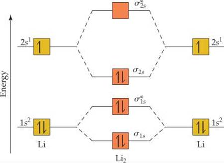
![]() FIGURE 9.35 Energy-level diagram for the Li2 molecule.
FIGURE 9.35 Energy-level diagram for the Li2 molecule.
Each Li atom has three electrons, so six electrons must be placed in Li2 MOs. As shown in Figure 9.35, these electrons occupy the σ1s, ![]() , and σ2s MOs, each with two electrons. There are four electrons in bonding orbitals and two in antibonding orbitals, so the bond order is
, and σ2s MOs, each with two electrons. There are four electrons in bonding orbitals and two in antibonding orbitals, so the bond order is ![]() (4 – 2) = 1. The molecule has a single bond, in agreement with its Lewis structure.
(4 – 2) = 1. The molecule has a single bond, in agreement with its Lewis structure.
Because both the σ1s and ![]() MOs of Li2 are completely filled, the 1s orbitals contribute almost nothing to the bonding. The single bond in Li2 is due essentially to the interaction of the valence 2s orbitals on the Li atoms. This example illustrates the general rule that core electrons usually do not contribute significantly to bonding in molecules. The rule is equivalent to using only the valence electrons when drawing Lewis structures. Thus, we need not consider further the 1s orbitals while discussing the other period 2 diatomic molecules.
MOs of Li2 are completely filled, the 1s orbitals contribute almost nothing to the bonding. The single bond in Li2 is due essentially to the interaction of the valence 2s orbitals on the Li atoms. This example illustrates the general rule that core electrons usually do not contribute significantly to bonding in molecules. The rule is equivalent to using only the valence electrons when drawing Lewis structures. Thus, we need not consider further the 1s orbitals while discussing the other period 2 diatomic molecules.
The MO description of Be2 follows readily from the energy-level diagram for Li2. Each Be atom has four electrons (1s22s2), so we must place eight electrons in molecular orbitals. Thus, we completely fill the σ1s,![]() σ2s, and
σ2s, and ![]() MOs. With equal numbers of bonding and antibonding electrons, the bond order is zero; thus, Be2 does not exist.
MOs. With equal numbers of bonding and antibonding electrons, the bond order is zero; thus, Be2 does not exist.
![]() GIVE IT SOME THOUGHT
GIVE IT SOME THOUGHT
Would you expect Be2+ to be a stable ion?
Molecular Orbitals from 2p Atomic Orbitals
Before we can consider the remaining period 2 diatomic molecules, we must look at the MOs that result from combining 2p atomic orbitals. The interactions between p orbitals are shown in ![]() FIGURE 9.36, where we have arbitrarily chosen the internuclear axis to be the z-axis. The 2pzorbitals face each other head to head. Just as with s orbitals, we can combine 2pz orbitals in two ways. One combination concentrates electron density between the nuclei and is, therefore, a bonding molecular orbital. The other combination excludes electron density from the bonding region and so is an antibonding molecular orbital. In both MOs the electron density lies along the internuclear axis, so they are σ molecular orbitals: σ2p and
FIGURE 9.36, where we have arbitrarily chosen the internuclear axis to be the z-axis. The 2pzorbitals face each other head to head. Just as with s orbitals, we can combine 2pz orbitals in two ways. One combination concentrates electron density between the nuclei and is, therefore, a bonding molecular orbital. The other combination excludes electron density from the bonding region and so is an antibonding molecular orbital. In both MOs the electron density lies along the internuclear axis, so they are σ molecular orbitals: σ2p and ![]() .
.
The other 2p orbitals overlap sideways and thus concentrate electron density above and below the internuclear axis. MOs of this type are called pi (π) molecular orbitals by
![]() GO FIGURE
GO FIGURE
In what types of MOs do we find nodal planes?
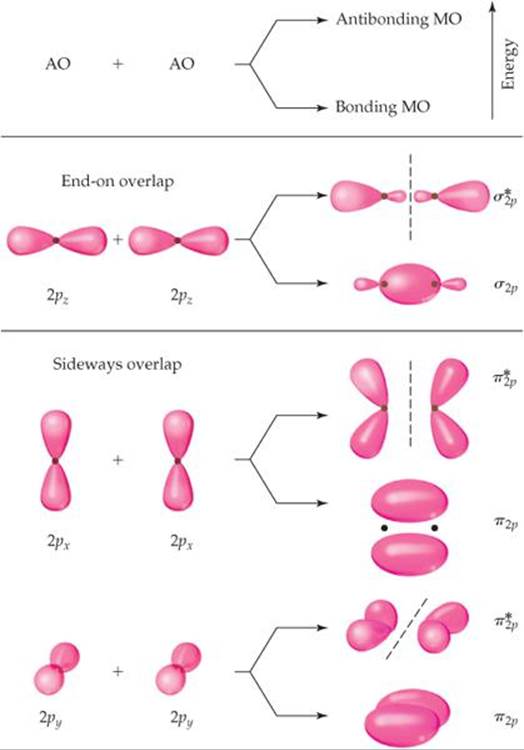
![]() FIGURE 9.36 Contour representations of the molecular orbitals formed by 2p orbitals.
FIGURE 9.36 Contour representations of the molecular orbitals formed by 2p orbitals.
 A CLOSER LOOK
PHASES IN ATOMIC AND MOLECULAR ORBITALS
Our discussion of atomic orbitals in Chapter 6 and molecular orbitals in this chapter highlights some of the most important applications of quantum mechanics in chemistry. In the quantum mechanical treatment of electrons in atoms and molecules, we are mainly interested in determining two characteristics of the electrons—their energies and their distribution in space. Recall that solving Schrödinger's wave equation yields the electron's energy, E, and wave function, ψ, but that ψ does not have a direct physical meaning. ![]() (Section 6.5) The contour representations of atomic and molecular orbitals we have presented thus far are based on ψ2 (the probability density), which gives the probability of finding the electron at a given point in space.
(Section 6.5) The contour representations of atomic and molecular orbitals we have presented thus far are based on ψ2 (the probability density), which gives the probability of finding the electron at a given point in space.
Because probability densities are squares of functions, their values must be nonnegative (zero or positive) at all points in space. However, the functions themselves can have negative values. Consider, for example, the sine function plotted in ![]() FIGURE 9.37. In the top graph, the sine function is negative for x between 0 and – π and positive for x between 0 and +π. We say that the phase of the sine function is negative between 0 and – π and positive between 0 and +π. If we square the sine function (bottom graph), we get two peaks that are symmetrical about the origin. Both peaks are positive because squaring a negative number produces a positive number. In other words, we lose the phase information of the function upon squaring it.
FIGURE 9.37. In the top graph, the sine function is negative for x between 0 and – π and positive for x between 0 and +π. We say that the phase of the sine function is negative between 0 and – π and positive between 0 and +π. If we square the sine function (bottom graph), we get two peaks that are symmetrical about the origin. Both peaks are positive because squaring a negative number produces a positive number. In other words, we lose the phase information of the function upon squaring it.
Like the sine function, the more complicated wave functions for atomic orbitals can also have phases. Consider, for example, the representations of the 1s orbital in ![]() FIGURE 9.38. Note that here we plot this orbital a bit differently from what is shown in Section 6.6. The origin is the point where the nucleus resides, and the wave function for the 1s orbital extends from the origin out into space. The plot shows the value of ψ for a slice taken along the z-axis. Below the plot is a contour representation of the 1s orbital. Notice that the value of the 1s wave function is always a positive number. Thus, it has only one phase. Notice also that the wave function approaches zero only at a long distance from the nucleus. It therefore has no nodes, as we saw in Figure 6.21.
FIGURE 9.38. Note that here we plot this orbital a bit differently from what is shown in Section 6.6. The origin is the point where the nucleus resides, and the wave function for the 1s orbital extends from the origin out into space. The plot shows the value of ψ for a slice taken along the z-axis. Below the plot is a contour representation of the 1s orbital. Notice that the value of the 1s wave function is always a positive number. Thus, it has only one phase. Notice also that the wave function approaches zero only at a long distance from the nucleus. It therefore has no nodes, as we saw in Figure 6.21.
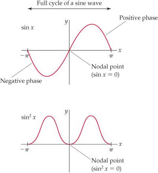
![]() FIGURE 9.37 Graphs for a sine function and the same function squared.
FIGURE 9.37 Graphs for a sine function and the same function squared.
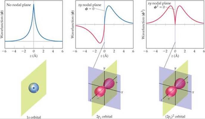
![]() FIGURE 9.38 Phases in wave functions of s and p atomic orbitals.
FIGURE 9.38 Phases in wave functions of s and p atomic orbitals.
In the Figure 9.38 graph for the 2pz orbital, the wave function changes sign when it passes through z = 0. Notice that the two halves of the wave have the same shape except that one has positive values and the other negative values. Analogously to the sine function, the wave function changes phase when it passes through the origin. Mathematically the 2pz wave function is equal to zero whenever z = 0. This corresponds to any point on the xy plane, so we say that the xy plane is a nodal plane of the 2pz orbital. The wave function for a p orbital is much like a sine function because it has two equal parts that have opposite phases. Figure 9.38 gives a typical representation used by chemists of the wave function for a pz orbital.* The plus and minus signs indicate the phases of the orbital. As with the sine function, the origin is a node.
The third graph in Figure 9.38 shows that when we square the wave function of the 2pz orbital, we get two peaks that are symmetrical about the origin. Both peaks are positive because squaring a negative number produces a positive number. Thus, we lose the phase information of the function upon squaring it just as we did for the sine function. When we square the wave function for the pz orbital, we get the probability density for the orbital, which is given as a contour representation in Figure 9.38. This is what we saw in the earlier presentation of p or- bitals. ![]() (Section 6.6) For this squared wave function, both lobes have the same phase and therefore the same sign. We use this representation throughout most of this book because it has a simple physical interpretation: The square of the wave function at any point in space represents the electron density at that point.
(Section 6.6) For this squared wave function, both lobes have the same phase and therefore the same sign. We use this representation throughout most of this book because it has a simple physical interpretation: The square of the wave function at any point in space represents the electron density at that point.
The lobes of the wave functions for the d orbitals also have different phases. For example, the wave function for a dxy orbital has four lobes, with the phase of each lobe opposite the phase of its nearest neighbors (![]() FIGURE 9.39). The wave functions for the other d orbitals likewise have lobes in which the phase in one lobe is opposite that in an adjacent lobe.
FIGURE 9.39). The wave functions for the other d orbitals likewise have lobes in which the phase in one lobe is opposite that in an adjacent lobe.
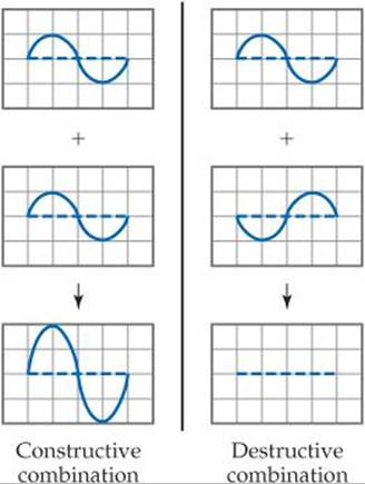
Why do we need to consider the complexity introduced by considering the phase of the wave function? While it is true that the phase is not necessary to visualize the shape of an atomic orbital in an isolated atom, it does become important when we consider overlap of orbitals in molecular orbital theory. Let's use the sine function as an example again. If you add two sine functions having the same phase, they add constructively, resulting in increased amplitude: but if you add two sine functions having opposite phases, they add destructively and cancel each other.
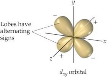
![]() FIGURE 9.39 Phases in d orbitals.
FIGURE 9.39 Phases in d orbitals.
The idea of constructive and destructive interactions of wave functions is key to understanding the origin of bonding and antibonding molecular orbitals. For example, the wave function of the σ1s MO of H2 is generated by adding the wave function for the 1s orbital on one atom to the wave function for the 1s orbital on the other atom, with both orbitals having the same phase. The atomic wave functions overlap constructively in this case to increase the electron density between the two atoms (![]() FIGURE 9.40). The wave function of the
FIGURE 9.40). The wave function of the ![]() MO of H2 is generated by subtracting the wave function for a 1s orbital on one atom from the wave function for a 1s orbital on the other atom. The result is that the atomic orbital wave functions overlap destructively to create a region of zero electron density between the two atoms—a node. Notice the similarity between this figure and Figure 9.32. In Figure 9.40 we use plus and minus signs to denote positive and negative phases in the H atomic orbitals. However, chemists may alternatively draw contour representations in different colors to denote the two phases.
MO of H2 is generated by subtracting the wave function for a 1s orbital on one atom from the wave function for a 1s orbital on the other atom. The result is that the atomic orbital wave functions overlap destructively to create a region of zero electron density between the two atoms—a node. Notice the similarity between this figure and Figure 9.32. In Figure 9.40 we use plus and minus signs to denote positive and negative phases in the H atomic orbitals. However, chemists may alternatively draw contour representations in different colors to denote the two phases.
When we square the wave function of the ![]() MO, we get the electron density representation which we saw earlier, in Figure 9.32. Notice once again that we lose the phase information when we look at the electron density.
MO, we get the electron density representation which we saw earlier, in Figure 9.32. Notice once again that we lose the phase information when we look at the electron density.
RELATED EXERCISES: 9.103, 9.115, 9.117
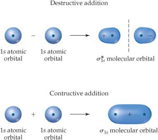
![]() FIGURE 9.40 Molecular orbitals from atomic orbital wave functions.
FIGURE 9.40 Molecular orbitals from atomic orbital wave functions.
analogy to π bonds. We get one π bonding MO by combining the 2px atomic orbitals and another from the 2py atomic orbitals. These two π2p molecular orbitals have the same energy; in other words, they are degenerate. Likewise, we get two degenerate ![]() antibonding MOs that are perpendicular to each other like the 2p orbitals from which they were made. These
antibonding MOs that are perpendicular to each other like the 2p orbitals from which they were made. These ![]() orbitals have four lobes, pointing away from the two nuclei, as shown in Figure 9.36. The 2pz orbitals on two atoms point directly at each other. Hence, the overlap of two 2pz orbitals is greater than that of two 2px or 2py orbitals. From rule 3 we therefore expect the σ2p MO to be lower in energy (more stable) than the π2p MOs. Similarly, the
orbitals have four lobes, pointing away from the two nuclei, as shown in Figure 9.36. The 2pz orbitals on two atoms point directly at each other. Hence, the overlap of two 2pz orbitals is greater than that of two 2px or 2py orbitals. From rule 3 we therefore expect the σ2p MO to be lower in energy (more stable) than the π2p MOs. Similarly, the ![]() MO should be higher in energy (less stable) than the
MO should be higher in energy (less stable) than the ![]() MOs.
MOs.
Electron Configurations for B2 through Ne2
We can combine our analyses of MOs formed from s orbitals (Figure 9.32) and from p orbitals (Figure 9.36) to construct an energy-level diagram (![]() FIGURE 9.41) for homonuclear diatomic molecules of the elements boron through neon, all of which have valence 2s and 2p atomic orbitals. The following features of the diagram are notable:
FIGURE 9.41) for homonuclear diatomic molecules of the elements boron through neon, all of which have valence 2s and 2p atomic orbitals. The following features of the diagram are notable:
1. The 2s atomic orbitals are substantially lower in energy than the 2p atomic orbitals. ![]() (Section 6.7) Consequently, both MOs formed from the 2s orbitals are lower in energy than the lowest-energy MO derived from the 2p atomic orbitals.
(Section 6.7) Consequently, both MOs formed from the 2s orbitals are lower in energy than the lowest-energy MO derived from the 2p atomic orbitals.
2. The overlap of the two 2pz orbitals is greater than that of the two 2px or 2py orbitals. As a result, the bonding σ2p MO is lower in energy than the π2p MOs, and the anti-bonding ![]() MO is higher in energy than the
MO is higher in energy than the ![]() MOs.
MOs.
3. Both the π2p and ![]() MOs are doubly degenerate; that is, there are two degenerate MOs of each type.
MOs are doubly degenerate; that is, there are two degenerate MOs of each type.
Before we can add electrons to Figure 9.41, we must consider one more effect. We have constructed the diagram assuming no interaction between the 2s orbital on one atom and the 2p orbitals on the other. In fact, such interactions can and do take place. ![]() FIGURE 9.42 shows the overlap of a 2s orbital on one of the atoms with a 2p orbital on the other. These interactions increase the energy difference between the σ2s and σ2p MOs, with the σ2s energy decreasing and the σ2p energy increasing (Figure 9.42). These 2s-2p interactions can be strong enough that the energetic ordering of the MOs can be altered: For B2, C2, and N2, the σ2p MO is above the π2p MOs in energy. For O2, F2, and Ne2, the σ2p MO is below the π2p MOs .
FIGURE 9.42 shows the overlap of a 2s orbital on one of the atoms with a 2p orbital on the other. These interactions increase the energy difference between the σ2s and σ2p MOs, with the σ2s energy decreasing and the σ2p energy increasing (Figure 9.42). These 2s-2p interactions can be strong enough that the energetic ordering of the MOs can be altered: For B2, C2, and N2, the σ2p MO is above the π2p MOs in energy. For O2, F2, and Ne2, the σ2p MO is below the π2p MOs .
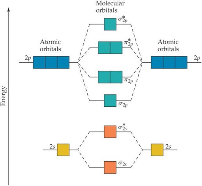
![]() FIGURE 9.41 Energy-level diagram for MOs of period 2 homonuclear diatomic molecules. The diagram assumes no interaction between the 2s atomic orbital on one atom and the 2p atomic orbitals on the other atom, and experiment shows that it fits only for O2, F2, and Ne2.
FIGURE 9.41 Energy-level diagram for MOs of period 2 homonuclear diatomic molecules. The diagram assumes no interaction between the 2s atomic orbital on one atom and the 2p atomic orbitals on the other atom, and experiment shows that it fits only for O2, F2, and Ne2.
![]() GO FIGURE
GO FIGURE
Which molecular orbitals have switched relative energy in the group on the right as compared with the group on the left?
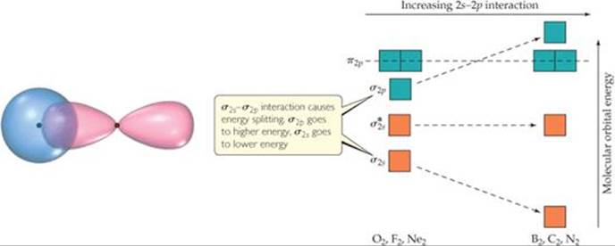
![]() FIGURE 9.42 The effect of interactions between 2s and 2p atomic orbitals.
FIGURE 9.42 The effect of interactions between 2s and 2p atomic orbitals.
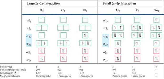
Given the energy ordering of the molecular orbitals, it is a simple matter to determine the electron configurations for the diatomic molecules B2 through Ne2. For example, a boron atom has three valence electrons. (Remember that we are ignoring the 1s electrons.) Thus, for B2 we must place six electrons in MOs. Four of them fill the σ2s and ![]() MOs, leading to no net bonding. The fifth electron goes in one π2p MO, and the sixth goes in the other π2p MO, with the two electrons having the same spin. Therefore, B2 has a bond order of 1.
MOs, leading to no net bonding. The fifth electron goes in one π2p MO, and the sixth goes in the other π2p MO, with the two electrons having the same spin. Therefore, B2 has a bond order of 1.
Each time we move one element to the right in period 2, two more electrons must be placed in the diagram of Figure 9.41. For example, on moving to C2, we have two more electrons than in B2, and these electrons are placed in the π2p MOs, completely filling them. The electron configurations and bond orders for B2 through Ne2 are given in ![]() FIGURE 9.43.
FIGURE 9.43.
Electron Configurations and Molecular Properties
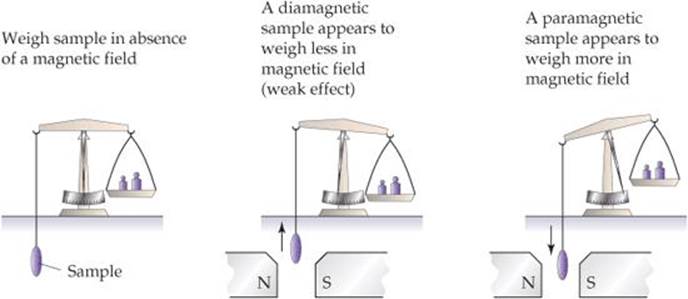
The way a substance behaves in a magnetic field can in some cases provide insight into the arrangements of its electrons. Molecules with one or more unpaired electrons are attracted to a magnetic field. The more unpaired electrons in a species, the stronger the attractive force. This type of magnetic behavior is called paramagnetism.
Substances with no unpaired electrons are weakly repelled by a magnetic field. This property is called diamagnetism. The distinction between paramagnetism and diamagnetism is nicely illustrated in an older method for measuring magnetic properties (![]() FIGURE 9.44). It involves weighing the substance in the presence and absence of a magnetic field. A paramagnetic substance appears to weigh more in the magnetic field; a diamagnetic substance appears to weigh less. The magnetic behaviors observed for the period 2 diatomic molecules agree with the electron configurations shown in Figure 9.43.
FIGURE 9.44). It involves weighing the substance in the presence and absence of a magnetic field. A paramagnetic substance appears to weigh more in the magnetic field; a diamagnetic substance appears to weigh less. The magnetic behaviors observed for the period 2 diatomic molecules agree with the electron configurations shown in Figure 9.43.
![]() GIVE IT SOME THOUGHT
GIVE IT SOME THOUGHT
Figure 9.43 indicates that C2 is diamagnetic. Would that be expected if the σ2p MO were lower in energy than the π2p MOs?
Electron configurations in molecules can also be related to bond distances and bond enthalpies. ![]() (Section 8.8) As bond order increases, bond distances decrease
(Section 8.8) As bond order increases, bond distances decrease
![]() GO FIGURE
GO FIGURE
What difference in electron configuration accounts for most of the difference between the bond enthalpy of N2 and that of F2?
![]() FIGURE 9.43 Molecular orbital electron configurations and some experimental data for period 2 diatomic molecules.
FIGURE 9.43 Molecular orbital electron configurations and some experimental data for period 2 diatomic molecules.
![]() FIGURE 9.44 Determining the magnetic properties of a sample.
FIGURE 9.44 Determining the magnetic properties of a sample.
and bond enthalpies increase. N2, for example, whose bond order is 3, has a short bond distance and a large bond enthalpy. The N2 molecule does not react readily with other substances to form nitrogen compounds. The relatively high bond order of the molecule helps explain its exceptional stability. We should also note, however, that molecules with the same bond orders do not have the same bond distances and bond enthalpies. Bond order is only one factor influencing these properties. Other factors include nuclear charge and extent of orbital overlap.
Bonding in O2 provides an interesting test case for molecular orbital theory. The Lewis structure for this molecule shows a double bond and complete pairing of electrons:
![]()
The short O—O bond distance (1.21 Å) and relatively high bond enthalpy (495 kJ/mol) are in agreement with the presence of a double bond. However, Figure 9.43 tells us that the molecule contains two unpaired electrons, a detail not discernible in the Lewis structure. Unpaired electrons mean paramagnetism, and the paramagnetism of O2 is demonstrated in ![]() FIGURE 9.45. The Lewis structure fails to account for this paramagnetism, but molecular orbital theory correctly predicts two unpaired electrons in the
FIGURE 9.45. The Lewis structure fails to account for this paramagnetism, but molecular orbital theory correctly predicts two unpaired electrons in the ![]() orbital. The MO description also correctly indicates a bond order of 2.
orbital. The MO description also correctly indicates a bond order of 2.
![]() GO FIGURE
GO FIGURE
What would you expect to see if liquid nitrogen were poured between the poles of the magnet?
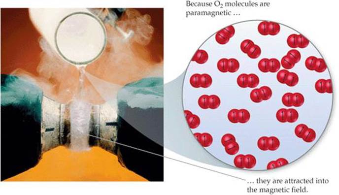
![]() FIGURE 9.45 Paramagnetism of O2.
FIGURE 9.45 Paramagnetism of O2.
Going from O2 to F2, we add two electrons, completely filling the ![]() MOs. Thus, F2 is expected to be diamagnetic and have an F—F single bond, in accord with its Lewis structure. Finally, the addition of two more electrons to make Ne2 fills all the bonding and antibonding MOs. Therefore, the bond order of Ne2 is zero, and the molecule is not expected to exist.
MOs. Thus, F2 is expected to be diamagnetic and have an F—F single bond, in accord with its Lewis structure. Finally, the addition of two more electrons to make Ne2 fills all the bonding and antibonding MOs. Therefore, the bond order of Ne2 is zero, and the molecule is not expected to exist.
SAMPLE EXERCISE 9.9 Molecular Orbitals of a Period 2 Diatomic Ion
For the O2+ ion, predict (a) number of unpaired electrons, (b) bond order, (c) bond enthalpy and bond length.
SOLUTION
Analyze Our task is to predict several properties of the cation O2+.
Plan We will use the MO description of O2+ to determine the desired properties. We must first determine the number of electrons in O2+ and then draw its MO energy diagram. The unpaired electrons are those without a partner of opposite spin. The bond order is one-half the difference between the number of bonding and antibonding electrons. After calculating the bond order, we can use Figure 9.43 to estimate the bond enthalpy and bond length.
Solve
(a) The O2+ ion has 11 valence electrons, one fewer than O2. The electron removed from O2 to form O2+ is one of the two unpaired ![]() electrons (see Figure 9.43). Therefore, O2+ has one unpaired electron.
electrons (see Figure 9.43). Therefore, O2+ has one unpaired electron.
(b) The molecule has eight bonding electrons (the same as O2) and three antibonding electrons (one fewer than O2). Thus, its bond order is
![]()
(c) The bond order of O2+ is between that for O2 (bond order 2) and N2 (bond order 3). Thus, the bond enthalpy and bond length should be about midway between those for O2 and N2, approximately 700 kJ/mol and 1.15 Å. (The experimentally measured values are 625 kJ/mol and 1.123 Å.)
PRACTICE EXERCISE
Predict the magnetic properties and bond orders of (a) the peroxide ion, O22–; (b) the acetylide ion, C22–.
Answers: (a) diamagnetic, 1; (b) diamagnetic, 3
Heteronuclear Diatomic Molecules
The principles we have used in developing an MO description of homonuclear diatomic molecules can be extended to heteronuclear diatomic molecules—those in which the two atoms in the molecule are not the same––and we conclude this section with a fascinating heteronuclear diatomic molecule—nitric oxide, NO.
The NO molecule controls several important human physiological functions. Our bodies use it, for example, to relax muscles, kill foreign cells, and reinforce memory. The 1998 Nobel Prize in Physiology or Medicine was awarded to three scientists for their research that uncovered the importance of NO as a “signaling” molecule in the cardiovascular system. NO also functions as a neurotransmitter and is implicated in many other biological pathways. That NO plays such an important role in human metabolism was unsuspected before 1987 because NO has an odd number of electrons and is highly reactive. The molecule has 11 valence electrons, and two possible Lewis structures can be drawn. The Lewis structure with the lower formal charges places the odd electron on the N atom:
![]()
Both structures indicate the presence of a double bond, but when compared with the molecules in Figure 9.43, the experimental bond length of NO (1.15 Å) suggests a bond order greater than 2. How do we treat NO using the MO model?
![]() GO FIGURE
GO FIGURE
How many valence-shell electrons are there in NO?
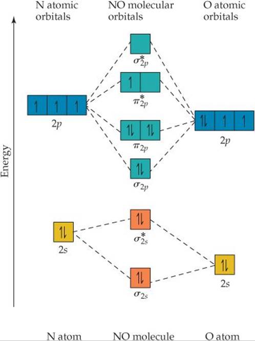
![]() FIGURE 9.46 The energy-level diagram for atomic and molecular orbitals in NO.
FIGURE 9.46 The energy-level diagram for atomic and molecular orbitals in NO.
If the atoms in a heteronuclear diatomic molecule do not differ too greatly in electronegativities, their MOs resemble those in homonuclear diatomics, with one important modification: The energy of the atomic orbitals of the more electronegative atom is lower than that of the atomic orbitals of the less electronegative element. In ![]() FIGURE 9.46, you see that the 2s and 2p atomic orbitals of oxygen are slightly lower than those of nitrogen because oxygen is more electronegative than nitrogen. The MO energy-level diagram for NO is much like that of a homonuclear diatomic molecule—because the 2s and 2p orbitals on the two atoms interact, the same types of MOs are produced.
FIGURE 9.46, you see that the 2s and 2p atomic orbitals of oxygen are slightly lower than those of nitrogen because oxygen is more electronegative than nitrogen. The MO energy-level diagram for NO is much like that of a homonuclear diatomic molecule—because the 2s and 2p orbitals on the two atoms interact, the same types of MOs are produced.
There is one other important difference in the MOs of heteronuclear molecules. The MOs are still a mix of atomic orbitals from both atoms, but in general an MO in a heteronuclear diatomic molecule has a greater contribution from the atomic orbital to which it is closer in energy. In the case of NO, for example, the σ2s bonding MO is closer in energy to the O 2s atomic orbital than to the N 2s atomic orbital. As a result, the σ2s MO has a slightly greater contribution from O than from N—the orbital is no longer an equal mixture of the two atoms, as was the case for the homonuclear diatomic molecules. Similarly, the ![]() antibonding MO is weighted more heavily toward the N atom because that MO is closest in energy to the N 2s atomic orbital.
antibonding MO is weighted more heavily toward the N atom because that MO is closest in energy to the N 2s atomic orbital.
 CHEMISTRY PUT TO WORK
Orbitals and Energy
Asked to identify the major technological challenge for the twenty-first century, you might say “energy,” reasoning that development of sustainable energy sources is crucial to meet the needs of future generations of people on our planet. Currently, the majority of the world, in one way or another, relies on exothermic combustion reactions of oil, coal, or natural gas to provide heat and power. These are all fossil fuels—carbon-containing compounds that are the long-term decomposition products of ancient plants and animals.
Fossil fuels are not renewable in the several-hundred-year time-frame in which we need them, but every day our planet receives plenty of energy from the Sun to easily power the world for millions of years. Whereas combustion of fossil fuels releases CO2 into the atmosphere, solar energy represents a renewable energy source that is potentially less harmful to the environment. One way to utilize solar energy is to convert it into electrical energy via photovoltaic solar cells. The problem with this alternative is that the current efficiency of solar-cell devices is low; only about 10-15% of sunlight is converted into useful energy. Furthermore, the cost of manufacturing solar cells is relatively high.
How does solar energy conversion work? Fundamentally, we need to be able to use photons from the Sun to excite electrons in molecules and materials to different energy levels. The brilliant colors around you—those of your clothes, the photographs in this book, the foods you eat—are due to the selective absorption of light by chemicals. Light excites electrons in molecules. In a molecular orbital picture, we can envision light exciting an electron from a filled molecular orbital to an empty one at higher energy. Because the MOs have definite energies, only light of the proper wavelengths can excite electrons. The situation is analogous to that of atomic line spectra. ![]() (Section 6.3) If the appropriate wavelength for exciting electrons is in the visible portion of the electromagnetic spectrum, the substance appears colored: Certain wavelengths of white light are absorbed; others are not. A green leaf appears green because green light is most strongly reflected by the leaf while other wavelengths of visible light are absorbed.
(Section 6.3) If the appropriate wavelength for exciting electrons is in the visible portion of the electromagnetic spectrum, the substance appears colored: Certain wavelengths of white light are absorbed; others are not. A green leaf appears green because green light is most strongly reflected by the leaf while other wavelengths of visible light are absorbed.
In discussing light absorption by molecules, we can focus on two MOs. The highest occupied molecular orbital (HOMO) is the MO of highest energy that has electrons in it. The lowest unoccupied molecular orbital (LUMO) is the MO of lowest energy that does not have electrons in it. In N2, for example, the HOMO is the σ2p MO and the LUMO is the ![]() MO (Figure 9.43).
MO (Figure 9.43).
The energy difference between the HOMO and the LUMO—known as the HOMO-LUMO gap—is related to the minimum energy needed to excite an electron in the molecule. Colorless or white substances usually have such a large HOMO-LUMO gap that visible light is not energetic enough to excite an electron to the higher level. The minimum energy needed to excite an electron from the HOMO to the LUMO in N2 corresponds to light with a wavelength of less than 200 nm, which is far into the ultraviolet part of the spectrum. ![]() (Figure 6.4) As a result, N2 cannot absorb visible light and is therefore colorless.
(Figure 6.4) As a result, N2 cannot absorb visible light and is therefore colorless.
The magnitude of the energy gap between filled and empty electronic states is critical for solar energy conversion. Ideally, we want a substance that absorbs as many solar photons as possible and then converts the energy of those photons into a useful form of energy. Titanium dioxide is a readily available material that can be reasonably efficient at converting light directly into electricity. However, TiO2 is white and absorbs only a small amount of the Sun's radiant energy. Scientists are working to make solar cells in which TiO2 is mixed with highly colored molecules, whose HOMO-LUMO gaps correspond to visible and near-infrared light. That way, the molecules can absorb more of the solar spectrum. The molecule's HOMO must also be higher in energy than the TiO2's HOMO so that the excited electrons can flow from the molecules into the TiO2, thereby generating electricity when the device is illuminated with light and connected to an external circuit.
![]() FIGURE 9.47 shows a solar cell made from ruthenium-containing molecules, which appear red, mixed with TiO2 in a paste that is sandwiched between two glass plates. Incoming light excites electrons on the ruthenium-containing molecules from occupied MOs to empty MOs. The electrons are then transferred into the TiO2 and move through the external circuit, generating enough current to run the small fan.
FIGURE 9.47 shows a solar cell made from ruthenium-containing molecules, which appear red, mixed with TiO2 in a paste that is sandwiched between two glass plates. Incoming light excites electrons on the ruthenium-containing molecules from occupied MOs to empty MOs. The electrons are then transferred into the TiO2 and move through the external circuit, generating enough current to run the small fan.
RELATED EXERCISES: 9.105, 9.116
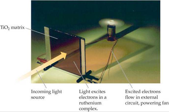
![]() FIGURE 9.47 Light into electricity.
FIGURE 9.47 Light into electricity.
We complete the MO diagram for NO by filling the MOs in Figure 9.46 with the 11 valence electrons. Eight bonding and three antibonding electrons give a bond order of ![]() (8 – 3) =
(8 – 3) = ![]() , which agrees better with experiment than the Lewis structures do. The unpaired electron resides in one of the
, which agrees better with experiment than the Lewis structures do. The unpaired electron resides in one of the ![]() MOs, which are more heavily weighted toward the N atom. (We could have placed this electron in either the left or right
MOs, which are more heavily weighted toward the N atom. (We could have placed this electron in either the left or right ![]() MO.) Thus, the Lewis structure that places the unpaired electron on nitrogen (the one preferred on the basis of formal charge) is the more accurate description of the true electron distribution in the molecule.
MO.) Thus, the Lewis structure that places the unpaired electron on nitrogen (the one preferred on the basis of formal charge) is the more accurate description of the true electron distribution in the molecule.
SAMPLE INTEGRATIVE EXERCISE Putting Concepts Together
Elemental sulfur is a yellow solid that consists of S8 molecules. The structure of the S8 molecule is a puckered, eight-membered ring (see Figure 7.26). Heating elemental sulfur to high temperatures produces gaseous S2 molecules:
S8(s) → 4 S2(g)
(a) The electron configuration of which period 2 element is most similar to that of sulfur? (b) Use the VSEPR model to predict the S – S – S bond angles in S8 and the hybridization at S in S8. (c) Use MO theory to predict the sulfur–sulfur bond order in S2. Do you expect this molecule to be diamagnetic or paramagnetic? (d) Use average bond enthalpies (Table 8.4) to estimate the enthalpy change for this reaction. Is the reaction exothermic or endothermic?
SOLUTION
(a) Sulfur is a group 6A element with an [Ne]3s23p4 electron configuration. It is expected to be most similar electronically to oxygen (electron configuration, [He]2s22p4), which is immediately above it in the periodic table.
(b) The Lewis structure of S8 is
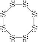
There is a single bond between each pair of S atoms and two nonbonding electron pairs on each S atom. Thus, we see four electron domains around each S atom and expect a tetrahe-dral electron-domain geometry corresponding to sp3 hybridization. Because of the nonbonding pairs, we expect the S — S — S angles to be somewhat less than 109.5°, the tetrahedral angle. Experimentally, the S — S — S angle in S8 is 108°, in good agreement with this prediction. Interestingly, if S8 were a planar ring, it would have S — S — S angles of 135°. Instead, the S8 ring puckers to accommodate the smaller angles dictated by sp3 hybridization.
(c) The MOs of S2 are analogous to those of O2, although the MOs for S2 are constructed from the 3s and 3p atomic orbitals of sulfur. Further, S2 has the same number of valence electrons as O2. Thus, by analogy with O2, we expect S2 to have a bond order of 2 (a double bond) and to be paramagnetic with two unpaired electrons in the ![]() molecular orbitals of S2.
molecular orbitals of S2.
(d) We are considering the reaction in which an S8 molecule falls apart into four S2 molecules. From parts (b) and (c), we see that S8 has S — S single bonds and S2 has S ═ S double bonds. During the reaction, therefore, we are breaking eight S — S single bonds and forming four S ═ S double bonds. We can estimate the enthalpy of the reaction by using Equation 8.12 and the average bond enthalpies in Table 8.4:
![]()
Recall that D(X—Y) represents the X—Y bond enthalpy. Because ΔHrxn > 0, the reaction is endothermic. ![]() (Section 5.4) The very positive value of ΔHrxn suggests that high temperatures are required to cause the reaction to occur.
(Section 5.4) The very positive value of ΔHrxn suggests that high temperatures are required to cause the reaction to occur.