Microreactors in Organic Chemistry and Catalysis, Second Edition (2013)
3. Microreactors Made of Glass and Silicon
3.6. Bonding Methods
If multilayer systems are to be manufactured, suitable bonding methods are needed. Attention must be paid not only to the mechanical stability of the bond but also to its resistance to chemicals and changes of temperature. Bonding by means of modern glues is not impossible but is rarely used in the construction of microreactors. The prerequisite for tension-free bonding is similar coefficients of linear thermal expansion. The following bonding processes are of importance:
anodic bonding of glass and silicon
glass fusion bonding
silicon direct bonding (silicon fusion bonding).
3.6.1 Anodic Bonding of Glass and Silicon
Metals or semiconductors can be joined to glass with a hermetic seal by anodic bonding. The process is used mainly to join silicon and borosilicate glass that contains a sufficiently high concentration of alkali, such as Borofloat 33 or Pyrex. It is a prerequisite that the surface is polished and clean and the materials to be bonded have approximately the same coefficient of thermal expansion. They are brought into close contact with one another at a temperature of 400–500 °C under direct current at a voltage of 700–1000 V. The high temperature makes the glass conduct ions. The electrostatic forces generated by the electric current not only strengthen the contact but also cause a drift of sodium ions across the boundary from the glass anode to the silicon cathode. Unsaturated oxygen bonds are left behind. With these, silicon atoms form strong chemical SiO bridges that constitute the bond. This process is used to make a covering for structures formed in silicon.
3.6.2 Glass Fusion Bonding
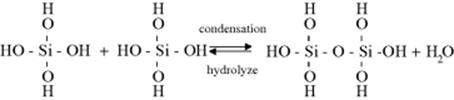
Thermal bonding of glass is similar to direct bonding of silicon. A distinction is made between two methods: with and without plastic deformation. For extremely high precision components, the method without plastic deformation is employed. As in the case of silicon direct bonding, the hydrophilic wafers are first “pre-bonded.” This brings the hydrophilic silica gel layer on each surface into contact with each other. At temperatures above 350 °C, this silica gel layer condenses and the results are firm bridges across the surfaces that are in contact with one another (Scheme 3.1). In practice, the wafers are given heat treatment for several hours at between 400 and 450 °C. Because the temperature is lower than the transformation temperature, the wafers are still undistorted after the heat treatment. For all this to succeed, the surface quality and accuracy of shape are subject to very demanding specifications. The planarity must be better than 100 nm and the absolute roughness better than 1–2 nm. If this is not the case, and the wafers are not sufficiently even, or are too rough, as is the case with photostructurable glass after etching, the gap caused by the lack of planarity must be overcome by plastic deformation. This means that the wafers are bonded under slight pressure and at a bonding temperature in excess of the transformation temperature. The significant process parameters, temperature, pressure, and bonding time will depend on the nature of the surfaces – their roughness or curvature.
Scheme 3.1 Condensation of the silica gel layer to siloxane bridges.
The degree to which the whole component is deformed after bonding depends on the quality of the surface.
3.6.3 Silicon Direct Bonding (Silicon Fusion Bonding)
Direct bonding is used as a procedure to join two or more wafers made of silicon. The chemical process is similar to glass fusion bonding of glass, (Scheme 3.1). It is possible to bond the wafers in the oxidized state or to dip them first into a solution of NH4OH: H2O2: H2O to make them hydrophilic; by this means, OH bonds are formed at the surface. Then, one wafer is laid on top of another, and they are pressed together. The wafers now adhere by virtue of van-der-Waals forces, as the surfaces are extremely smooth and even. The wafers are then heat-treated in an oxidizing kiln, in which the atmosphere contains 5% O2 and 95% N2, for 60 min at 1050 °C. It results in firm Si—O bonds holding the wafers together.
If the wafers have been oxidized first, no hydrophilization is required, as SiO2 itself is hydrophilic.
By a plasma activation of the surfaces, the bonding temperature at comparable strength can be reduced to below 400 °C. This process opens up a new technology, especially in multilayer microsystems, as they are necessary for the production of microreactors. Polymers and metallization can be introduced before the bonding in the microreactor.
At an annealing temperature of 325 °C is almost reached, the mechanical strength of the base material. At 120 °C and corresponding activation, up to 80% of the strength of the base material can be achieved. This is sufficient for many applications.
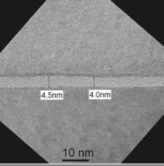
The Figure 3.21 shows a bonded microfluidic structure; Figure 3.22 shows a TEM image (transmission electron microscopy) of the bonding interface. Shown is the change in the material in the bonding interface by the thermal treatment. See Refs [32–34] for more details.
Figure 3.21 Low temperature silicon direct bonded microfluidic sensor element. Source: With courtesy of the CiS Forschungsinstitut für Mikrosensorik und Photovoltaik GmbH, Erfurt, Germany.
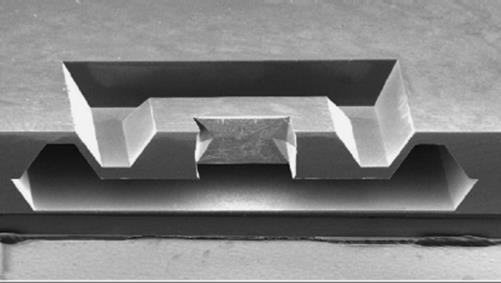
Figure 3.22 TEM images of interfacial bonding. Source: Prepared by the Fraunhofer Institute for Mechanics of Materials on behalf CiS Forschungsinstitut für Mikrosensorik und Photovoltaik GmbH, Erfurt, Germany.
3.6.4 Establishing Fluid Contact
The connections for fluid contact have the task of ensuring ingress of the starting materials to the microreactor and egress of the products. They are normally miniature hoses made of PTFE or pipes made of chemically resistant stainless steel. Common diameters are 1/8 and 1/16 in. Fittings with 1/4 in. UNF thread are employed for PTFE hoses, and the steel tubing is fixed with jubilee clips. A variety of methods are used to fix compatible connection points on the microreactor. Here, three of them will be described.
1. Casing: the microreactors are embedded into a casing. Female threads are integrated into the casing and furnished with O-ring gasket to seal against leakage of the substances. Adapters for screw fittings or hose clips are screwed into the female thread using conventional seals.
2. Self-supporting casing: Here, the reactor has a self-supporting casing, that is, the reactor is so solid that it is possible to fix the connections directly onto it. It does not need a separate casing. Sometimes, partial frames are used, enclosing only the components at the ingress points or the egress points, for an exemplar U form coupling body see in Figures 3.23a, and 3.24, the tube seals directly on the component. Or, the connections are fixed with hollow screws and double muffs. On one side of the double muff, there is the thread for the hollow screw, and on the opposite side, there is the ¼″-UNF thread or a screw fitting (Figure 3.23b).
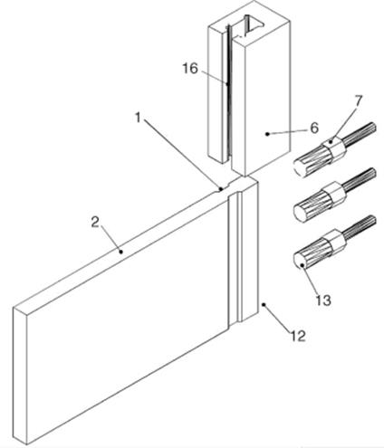
3. Another variant is shown in Figures 3.25 and 3.26. The figures show the expanded view and the general view of a connector system. The connector system is made up of the microreactors (2) with groove (microreactor) (1) and the profile rail (6), in which the fluid connector (7) is screwed and a force carry on the front face, the connector surface (12) of the microreactors (2). The profile rail is built up of a connector coupling with a c-shaped profile that encloses the front face connected microreactors. The connector coupling is made up of two shank-tile, left shank-tile (4) and right shank-tile (14), which are joined with a back bar (15). In the opposite side of back bar is the retaining bar (5) and it protrudes into the room. The retaining bar is built with a crack (16), in which the microreactors can slide. The microreactor has a retaining groove, which holds the connector coupling. Because of the geometry of connector coupling, it is prevented that the connector coupling twists and vertically switch to the surface side and the connector side. In the back bar (15), you can find internal thread that can screw in the connector of hoses (3) through the front surface of hoses (13) and seal up the connector surface (12).
4. The right size of female thread and the 1/4 in. UNF are manufactured in glass, as a direct component of the self-supporting casing or in connector pieces that are bonded onto the reactor. This method is particularly suitable for thin microreactors, see Figure 3.23c.
Figure 3.23 Possibilities for connecting fluidics to microreactors (a) 1: bedstop; 2: U form coupling body; 3: connection screw; and 4: microreactor [8]. (b) Self-supporting casing and hollow screws. (c) Self-supporting casing with female threads.
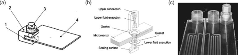
Figure 3.24 Partial frames with the microreactor.
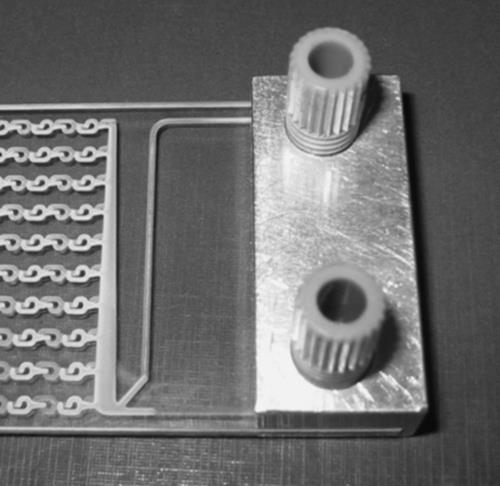
Figure 3.25 Microreactor made of glass with front port.
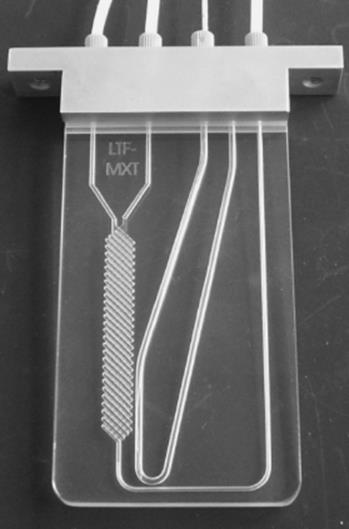
Figure 3.26 Exploded view of connector system 2.7.11 [36, 37].