Organic Chemistry I For Dummies, 2nd Edition (2014)
Part I. Getting Started with Organic Chemistry
Chapter 3. Speaking with Pictures: Drawing Structures
IN THIS CHAPTER
Perfecting your organic-speak
Drawing Lewis structures
Seeing structural abbreviations
Drawing resonance structures
I hope you’ve had the chance to listen in on a conversation between two chemists in the halls of a cavernous chemistry building as they discussed their experiments. Perhaps you overheard snatches of their conversation: “I don’t get it,” one might have said. “My proton NMR showed two multiplets one part per million upfield from the aromatic protons.” Or maybe you heard, “I made the alkene via the Wittig, but for the life of me I simply could not get the reduced nitro group to react with the t-butyl chloride using an SN1 in ethanol!” Or perhaps, “We return to planet Beldar with the earthlings in eight lunar cycles!” And you thought, “Now what language were they speaking?”
They were speaking organic, of course, which hasn’t been classified yet as a foreign language, but perhaps could be, because learning organic chemistry is a lot like learning a foreign language. Organic chemistry has its own jargon, as the snatches of conversation you overheard show (though after you’ve read this book and are fluent in organic, you’ll be able to understand what they were talking about). But I would argue that the similarity goes deeper than that. The words are different, too.
Before you can speak German or Japanese or Swahili — or any foreign language, for that matter — you need to learn what the different words mean. Similarly, before you can “speak organic,” you need to learn how to draw structures. Structures are the “words” of the organic chemist, and becoming fluent in drawing structures is absolutely essential in order to do well in organic chemistry. Drawing structures may seem strange at first, and probably even intimidating, but with practice you’ll soon get the hang of it. Like speaking a foreign language, with enough practice, drawing organic structures will simply become second nature (and kind of fun, too).
In this chapter, I give you the vocabulary for speaking organic chemistry by showing you how to draw organic structures using the standard Lewis convention. I also walk you through the ways that organic chemists abbreviate Lewis structures, both for clarity and for when they’re feeling lazy (which, admittedly, is most of the time). Finally, I show you how to draw resonance structures, which are used to correct for a flaw in the Lewis structure model.
MODELS AND MOLECULES
People have a hard time comprehending objects that are either huge or tiny. That’s because our minds think in terms of the sizes of the things we encounter in our daily lives. A kilometer is about as far as our walk across campus; 2 centimeters is about the length of our pinky tips. To us, these sizes make sense; we can relate to them. But comprehending gargantuan lengths, like the distance between the earth and a distant star millions of light-years away, or itty-bitty lengths, like the distance across an atom (a distance of only a few hundred picometers), is mind-boggling.
This difficulty creates a problem for chemists. How can they understand atoms and molecules if they’re so small that it boggles chemists’ minds just to think about them? How can chemists describe, organize, and classify things that they cannot see? In short, how can they be scientific about the study of chemistry?
In addition to our inability to comprehend such small things is the added complexity that atoms don’t behave in the same way as objects of a larger scale; they don’t behave like the things we see in our everyday lives — things that we can see or touch or throw, things like stink bombs or chemistry texts. Molecules behave in very bizarre ways as a result of their smallness, and human intuition based on the big world of everyday objects is no help in understanding the tiny world of molecules. For atoms, the classical physics that you’ve been taught since grade school fails disastrously. This is because something that is very, very small (like an electron) has been found to behave both like a particle (which you might expect) and as a wave (which you wouldn’t). Electrons are small enough that they have the ability to “tunnel” through a barrier (the equivalent of a person walking through a wall), and they can exist in two places simultaneously, in addition to other very bizarre behaviors.
So, chemists must use models to describe molecules and their weird behavior. Chemists use models to describe the way a molecule is put together — where the electrons are and which atoms are attached together and in what way — and to represent how reactions might occur. The primary model used in organic chemistry is the Lewis structure. Although Lewis structures are only approximate models of how molecules look in actuality, they really do an excellent job of showing the connectivity of atoms. These models, however, are not always perfect for describing the exact locations of certain electrons, as I discuss in the section about resonance structures later in the chapter.
Picture-Talk: Lewis Structures
A Lewis structure is the chemist’s way of depicting an infinitesimally small molecule on a macroscopic piece of paper. A Lewis structure shows what atoms are connected to each other, and it shows where the electrons in the molecule reside. Single bonds between two atoms are represented with a single line, signifying two shared electrons; double bonds are represented with a double line, signifying four shared electrons; and triple bonds are represented with a triple line, signifying six shared electrons (refer to Chapter 2 for more on bonding). Nonbonding electrons are indicated with dots on the atoms on which they reside.
Taking charge: Assigning formal charges
The first thing you want to be able to identify on a Lewis structure is which atoms have formal charges. Electrons are negatively charged, so an atom that is missing one or more electrons will have a positive charge. An atom that has one too many electrons will have a negative charge. Being able to quickly determine the charge on any atom in a given molecule is extremely important. So, here’s a quick-and-dirty equation for determining the formal charge on an atom:
formal charge on an atom = valence electrons – dots – sticks
Here dots is simply the number of lone-pair electrons around the atom, while sticks is the number of bonds off the atom. (A single bond is one stick; a double is two; a triple, three.) The best way to see this is to try one. So, apply this equation to NH2, shown in Figure 3-1, to calculate the formal charge on the nitrogen atom.
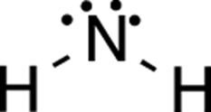
FIGURE 3-1: The amide ion.
Just plug the values into the formula. Nitrogen is in the fifth column of the periodic table and so has five valence electrons; it has four dots (four nonbonding electrons) and two sticks (two bonds).
formal charge = 5 valence electrons – 4 dots – 2 sticks = –1
The formal charge on the nitrogen, then, is –1, so in this molecule nitrogen is anionic. Using this same approach, you should be able to apply this formula quickly to all the atoms in a molecule. Still, even though this equation is fairly simple to use, applying it to every atom in a molecule is tedious. You want to be able to simply look at a structure and, within a couple seconds, determine which atoms have charges.
Fortunately, with enough practice, you’ll quickly recognize certain patterns for different atoms that will indicate whether the atoms are neutral, positively charged, or negatively charged. For example, if carbon has four bonds, it will be neutral, if it has three bonds, it will be positively charged, and if it has three bonds and a lone pair, it will be negatively charged. You can see this generality to be true for yourself by plugging these different configurations for carbon into the equation for formal charge just shown.
 Knowing that a neutral carbon atom always has four bonds lets you scan a molecule quickly to identify carbons that don’t have four bonds, and, when you find one, say to yourself, “Aha! This carbon must have a charge.” For nitrogen, you look to see which nitrogen atoms don’t have three bonds and a lone pair; for oxygen, you look to see which ones don’t have two bonds and two lone pairs, and so forth. This way, you won’t need to apply the formula to every atom (although you can if you need to); you just look to see which atoms differ from the typical number of bonds found around an atom in its neutral form. I show these patterns for the most common elements in organic compounds in Figure 3-2.
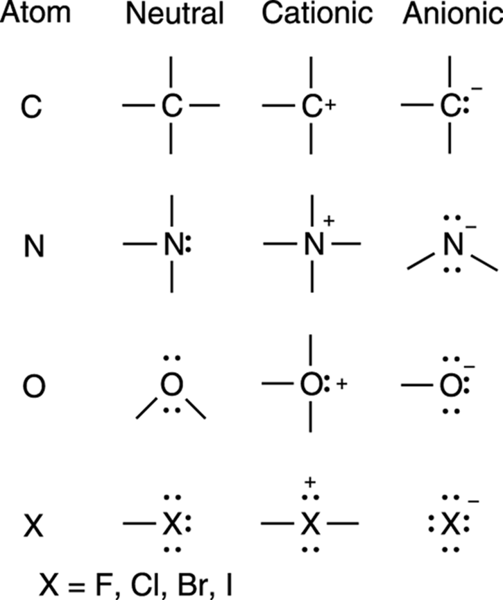
FIGURE 3-2: Some common charges on atoms.
Chemists, in fact, use specific jargon to describe typical bonding patterns of atoms. The number of bonds around a neutral atom is referred to as that atom’s valency. Carbon is tetravalent (tetra means four), because carbon has four bonds to other atoms when it’s neutral; nitrogen is trivalent, because it has three bonds to other atoms (plus a lone pair) when it’s neutral; oxygen is divalent, because it has two bonds to other atoms (plus two lone pairs) in its neutral form; and halogens (elements such as fluorine [F], chlorine [Cl], bromine [Br], and iodine [I]) are monovalent, because they have one bond to another atom (plus three lone pairs) when they’re neutral.
Drawing structures
In addition to calculating charges, you also need to be able to quickly draw organic structures and interpret what the drawings mean, because these are the words you’ll use to speak organic chemistry.
Organic chemists draw structures in several different ways, and because the different styles have different uses, you should be familiar with all of them. The most complete way of drawing organic structures is with the full Lewis structure (sometimes called a Kekulé structure). A Lewis structure explicitly draws out all the bonds in a molecule (an example is given in Figure 3-3). The lone pairs on atoms may or may not be shown in a Lewis structure (they often aren’t), but formal charges are always shown. Later in this chapter, I show you how to determine the number of lone pairs on a given atom when these lone pairs aren’t explicitly shown (don’t worry, it’s not difficult).
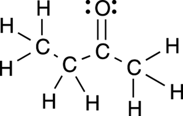
FIGURE 3-3: The full Lewis structure for butanone.
Full Lewis structures most faithfully show the structure of a molecule and how the molecule is put together, because every bond and every atom is shown. But this method of structure drawing can become tedious and overwhelming when you draw larger molecules. To make structure drawing quicker and the interpretation of change in a molecule easier to spot, chemists use shorthand notation, just as you may use abbreviations when you text your friends.
Atom packing: Condensed structures
One such structure abbreviation of the full Lewis structure is called a condensed structure. In a condensed structure, the bonds between carbon and hydrogens are not explicitly shown; instead, each carbon and the attached hydrogens are grouped together into a cluster (such as CH2 or CH3), and these clusters are written in a chain that shows the connectivity between the carbons. The carbon-carbon bonds may be explicitly shown, or they may simply be assumed. Condensed structures with shown and unshown bonds between the clusters are given in Figure 3-4 for the molecule butanone.
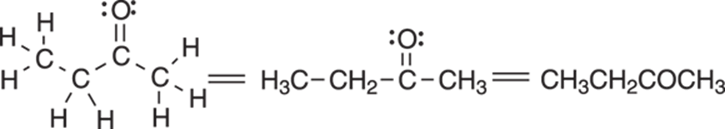
FIGURE 3-4: Condensed structures of butanone.
Condensed structures are most useful when the molecule consists of a straight chain of atoms; elaborate structures that contain rings are more difficult to portray with condensed structures. When two or more identical groups are attached to an atom, parentheses with a subscript can be used to abbreviate the structure even further. In this case, the subscript indicates the number of identical groups that are attached to the atom. An example of this grouping for condensed structures is given in Figure 3-5 for diethyl ether.
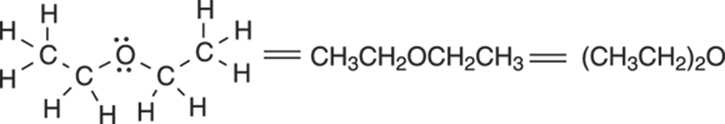
FIGURE 3-5: Condensed structures for diethyl ether.
Parentheses are also used when a chain becomes very long and a unit is repeated many times (for instance, when a CH2 unit is repeated). Here, the subscript after the parentheses indicates how many times the unit is repeated, as shown for heptane in Figure 3-6.
![]()
FIGURE 3-6: Heptane condensed structure.
Structural shorthand: Line-bond structures
The most common method of structure drawing, however, is called the line-bond structure. In these structures, each point (or node) on a jagged line is assumed to be a carbon atom. Hydrogens attached to carbons are not explicitly shown in a line-bond structure. But because each carbon is presumed to be neutral unless a charge is explicitly written on the structure, this method of drawing structures assumes that you can mentally supply the number of hydrogens attached to each carbon by making the total number of bonds equal to four. So, if a neutral carbon is shown having two bonds to other carbon atoms, then it must also be bonded to two additional hydrogens that are not shown. Figure 3-7 shows the line-bond structure for isoheptane.
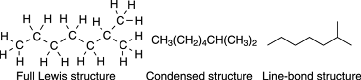
FIGURE 3-7: Structures for isooctane.
 The general rules for line-bond structures are as follows:
· Each point on a jagged line is assumed to be a carbon atom.
· The ends (tips) of lines are assumed to be carbon atoms.
· All hydrogens attached to non-carbon elements (like N, O, S, and so on) must be explicitly shown.
· All atoms are presumed to be neutral unless a charge is specifically shown.
Converting Lewis structures to line-bond structures
As shown in Figure 3-8, to convert a full Lewis structure to a line-bond structure, a jagged line is used to represent straight chain molecules, with each point (including the ends of the structure) representing a carbon atom.
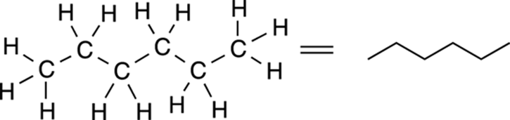
FIGURE 3-8: Line-bond structure for hexane.
In line-bond structures, rings are represented by polygons, with each point representing a carbon atom, as shown for the five-membered ring in Figure 3-9. A triangle is a three-carbon ring (which, of course, is the smallest possible ring size); a square is a four-carbon ring; a pentagon is a five-carbon ring; and so forth.
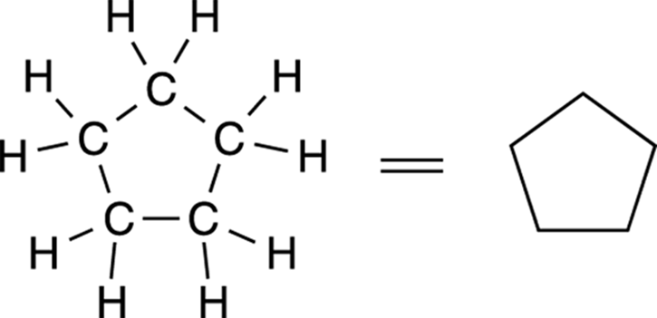
FIGURE 3-9: Cyclopentane line-bond structure.
Multiple bonds are explicitly drawn out. Triple bonds are drawn in a straight line, as shown in Figure 3-10, and are not jagged like single bonds (I talk about why in Chapter 11).
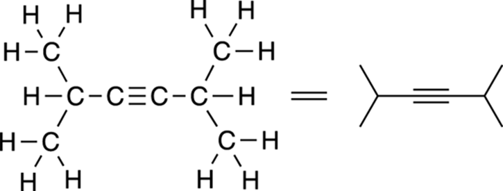
FIGURE 3-10: Diisopropyl acetylene.
Hydrogens attached to any atom other than carbon (atoms such as oxygen [O], sulfur [S], and nitrogen [N]) must be explicitly shown; only hydrogens attached to carbons are not shown. Figure 3-11 shows an example of how to draw non-carbon atoms in line-bond structures.
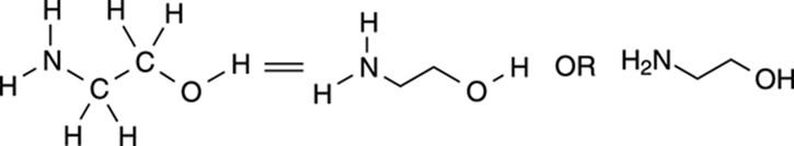
FIGURE 3-11: Ethanolamine.
This line-bond method of structural representation is probably the method most commonly used by organic chemists — it’s easy to draw, it’s convenient, and it’s uncluttered in comparison to the full Lewis structure. My guess is that you’ll prefer, at least initially, to use full Lewis structures to represent molecules rather than this line-bond method, because Lewis structures don’t require you to mentally supply the missing hydrogens.
At first, using full Lewis structures in your drawings is probably an excellent idea, because this structure has no structural abbreviations (just as you would want to learn how to speak with proper English before learning LOL and OMG). But you should familiarize yourself with line-bond drawings right away so you can quickly become comfortable using them. Your organic chemistry textbook — and your teacher — will likely use line-bond structures almost exclusively later in the course, so knowing how to draw and interpret line-bond structures will be to your advantage.
Determining the number of hydrogens on line-bond structures
Being able to quickly “see” how many hydrogens are attached to each carbon in a line-bond structure takes practice. But the math, at least, is simple. A neutral carbon has four bonds. So, if a line-bond structure shows a carbon that has three bonds to other atoms, it must have one implicit hydrogen; if it shows a carbon that has two bonds, it must have two implicit hydrogens; if it shows a carbon that has only one bond, it must have three implicit hydrogens. In Figure 3-12, I show a line-bond structure and point out the number of hydrogens assumed to be attached to each of the carbons.
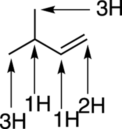
FIGURE 3-12: Counting the assumed hydrogens.
Getting the hang of drawing line-bond structures takes a bit of work, but there’s a nice payoff once you do because you’ll be able to draw structures much faster (which is a significant issue when you’re dealing with a large number of structures), and you’ll be able to see chemical changes much more easily than if you were using the full Lewis structures (important when you begin chemical reactions of organic molecules). You’ll also better understand the textbook and your instructor when they use these line-bond structures.
Quite often, you see structures drawn that combine these three different methods of structure drawing. In other words, it’s not a requirement that an entire molecule be drawn using only one of the drawing methods. It’s not unusual to see parts of a molecule drawn out with the full Lewis representation, parts drawn in condensed structure form, and parts drawn using the line-bond format. Chemists often have good reasons for doing this — to emphasize certain important parts of a molecule, for example — but at the beginning, when you’re just trying to get everything straight in your head, you can easily get confused if a structure is drawn that combines the different structure drawing styles. Figure 3-13 shows an organic molecule that was drawn using a combination of structure drawing methods.
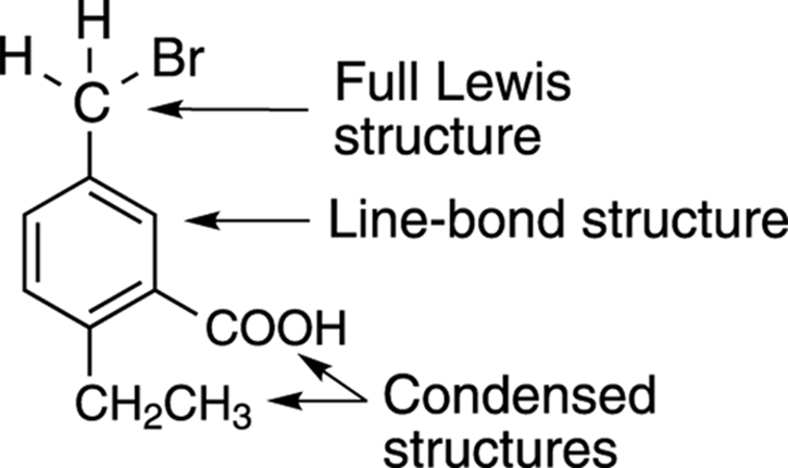
FIGURE 3-13: A structure drawing that combines the three different styles.
So lonely: Determining lone pairs on atoms
Most often, lone pairs on atoms are not shown explicitly because chemists assume that you can determine for yourself the number of lone pairs on the atom. One way to determine the number of lone pairs (if they aren’t shown) is to simply plug the information into the rearranged equation for the formal charge, where dots is simply the number of nonbonding electrons.
dots = valence electrons – sticks – formal charge
The best way to master this is by practicing, so go ahead and try one. To determine the number of lone pairs on the nitrogen atom in NH2–, you plug into the equation the number of valence electrons for nitrogen (5), the number of sticks (2, because nitrogen has two bonds, one with each of the two hydrogens), and the formal charge on the atom (–1 in this case).
dots = 5 – 2 – (–1) = 4
So, NH2– has four nonbonding electrons, or two lone pairs of electrons (because there are two “dots” in every lone pair).
As is the case with distinguishing formal charges, after a while you’ll become practiced enough at figuring out the number of lone pairs that you won’t need to do this calculation, because you’ll recognize the patterns of electrons and bonds. At that point, you’ll know that a negatively charged nitrogen will have two lone pairs, that a negatively charged carbon will have one lone pair, that a neutral oxygen will have two lone pairs, and so on (refer to Figure 3-2 for the other patterns). But it’s going to take some work before it becomes second nature, so practice, practice, practice!
Problem Solving: Arrow Pushing
Now for the squishy part. If structures are the words of organic chemistry, then arrow pushing is the grammar and syntax of organic chemistry. And I know how much everyone loves grammar. Knowing what the arrows represent and how to use them properly will help you understand organic chemistry. (Like English professors, chemistry professors are very picky about using this “grammar” correctly.)
In organic chemistry, you see five major types of arrows (see Figure 3-14):
· Resonance arrow: Used to indicate movement between resonance structures (which I talk about in the next section).
· Equilibrium arrow: Used to show reactions governed by equilibria (see Chapter 10). Making one of the equilibrium arrows longer shows the direction of the equilibrium in a reaction (in other words, which side of the reaction — reactants or products — is favored).
· Reaction arrow: Used to show the change of molecules by a reaction.
· Full-headed arrow: Used to show the movement of two electrons.
· Half-headed arrow: Used to show the movement of one electron.
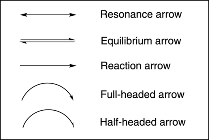
FIGURE 3-14: The types of arrows used in organic chemistry.
Electrons, electrons, electrons: These little guys are the keys to chemistry. They’re what organic chemists care most dearly about. The neutrons and protons stay fixed in their little round shack at the nucleus, but the electrons are adventurous, bustling about making new bonds and breaking old ones, so organic chemists concern themselves mostly with what happens to the electrons. Because electrons form and break bonds (and protons and neutrons do not), the focus throughout organic chemistry is on where the electrons are and where they’re going in a chemical reaction. So, for the most part, you ignore the protons and neutrons in the nucleus, because these remain constant, and focus your attention on what’s happening with the electrons.
Organic chemists use half- and full-headed arrows to show the movement of electrons (sometimes half-headed arrows are called fishhook arrows because they look like fishhooks). Full-headed arrows are much more common than half-headed arrows, simply because most reactions involve the movement of lone pairs and bonds — each of which contains two electrons. Half-headed arrows are used for describing free radical reactions (described in Chapter 8), because these reactions involve the movement of single electrons. You’ll need to become as good as Robin Hood at using these types of arrows.
Mastery of so-called “arrow pushing” is essential to mastering organic chemistry — and, importantly, to doing well in the class! Arrow pushing is something that can’t be learned in one sitting. This kind of grammar takes lots and lots of practice to master. Arrow pushing is organic-speak for showing how a chemical change takes place. To do this, organic chemists use these single- and full-headed arrows, which show how you get from one structure to the next in a reaction (or in a resonance structure, which I describe in the next section) by showing the movement of electrons.
Full-headed arrows, by convention, are used to show the movement of electrons. Therefore, you always draw arrows from electrons toward where they’re going, never the other way around. I think most students would prefer to have arrows show the movement of atoms rather than show the movement of electrons. But using an arrow to show the movement of atoms is wrong, and if you make your arrows do that on an exam, it will almost certainly cost you points. If, for example, you want to show water being protonated (receiving an H+ ion) by acid, you would show one of the lone pairs on water’s oxygen attacking the proton (the H+), not the proton moving onto the water.
Because H+ has no electrons (hydrogen has lost its one electron to become a positively charged cation), you may ask when would it be correct to show an arrow coming from an H+. As King Lear may have said had he been an organic chemist: “Never! never! never! never! never!” Figure 3-15 shows the correct and incorrect ways to show the movement of electrons using a double-headed arrow.
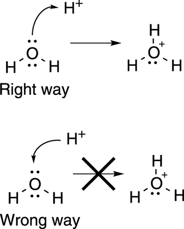
FIGURE 3-15: The right and wrong ways to use full-headed arrows to show electron movement.
Drawing Resonance Structures
Lewis structures show the locations of electrons correctly most of the time — but not always. To correct for a flaw in showing the locations of certain electrons in Lewis structures, chemists use resonance structures. Organic chemists use these resonance structures to account for a flaw in showing the locations of certain lone-pair and pi electrons in Lewis structures (pi electrons are electrons found in pi bonds; refer to Chapter 2). You can’t get through organic chemistry without being able to draw resonance structures and without understanding what these structures mean.
The Lewis structure for a carboxylate anion (RCO2–, where R stands for the rest of the molecule) provides a good example of how Lewis structures are not always the best way to describe certain molecules. This Lewis structure (see Figure 3-16) predicts one double bond between carbon and one of the oxygens, and one single bond between carbon and the oxygen that contains the negative charge. According to this Lewis structure, the two C-O bonds are different. Instead, the actual structure is one in which both of the carbon-oxygen bonds are identical — with each C-O bond having some single-bond qualities and some double-bond qualities — and each of the oxygens shares the negative charge equally.
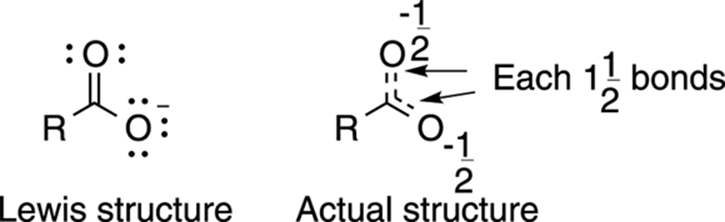
FIGURE 3-16: The Lewis structure of a carboxylate ion compared to the actual structure.
Because this Lewis structure fails to correctly account for the location of the electrons, organic chemists use resonance structures to correct for this flaw. But how do you know when to use resonance structures to correct for this flaw? In general, any time more than one valid Lewis structure can be drawn for a given molecule, each of these alternate structures is considered a resonance structure, and the actual structure of a molecule will look like a hybrid of all the different resonance structures. That leads to the next question: How do you find all the alternative resonance structures?
Rules for resonance structures
Chemists use arrow pushing to find all alternative resonance structures for a molecule. Here are the three basic rules for finding alternative resonance structures:
· Atoms are fixed and cannot move. Because the purpose of resonance structures is simply to account for alternative locations of electrons, all atoms stay in fixed positions. Only the distribution of the electrons in the molecule changes from one resonance structure to the next.
· Only lone-pair electrons and pi electrons — which are only found in double and triple bonds — can move. Single bonds stay put (to review pi bonds, refer to Chapter 2).
· You can’t break the octet rule. This law still applies. To put this rule into practical terms, the sum of an atom’s lone pairs and bonds cannot be greater than 4 for second-row elements.
For example, the carboxylate anion in Figure 3-17 can be represented by two different and equally valid Lewis structures, one in which the negative charge rests on the top oxygen, and one in which the charge rests on the bottom oxygen. So, which Lewis structure represents the actual molecule? The answer: Neither one does! In fact, no single resonance structure describes a molecule perfectly, but the correct structure lies somewhere in between; the correct structure is a hybrid of all the resonance structures. In the case of the carboxylate anion, each of the C-O bonds is neither a double bond nor a single bond, but a bond that is somewhere in between (one-and-a-half bonds).
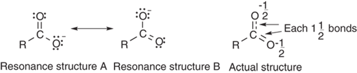
FIGURE 3-17: Double-headed resonance arrows are used to convert between resonance forms.
 You may ask why chemists don’t simply draw the hybrid drawing (like the one shown in the right-hand portion of Figure 3-17), with the dotted line representing the partial (one-and-a-half) bonding character. One reason is that this drawing doesn’t show the number of electrons in the molecule, so this drawing is an inconvenient representation for showing the reactions of that molecule. Instead, multiple resonance structures are typically used to represent the hybrid nature of the actual structure.
Note the use of the double-headed resonance arrow in Figure 3-17 to show the two equivalent resonance structures. This arrow serves as a reminder that resonance is not a reaction, not an equilibrium process, and not a change of any kind in a molecule. Instead, these resonance structures are simply a way of correcting the flaw in Lewis theory and accounting for the proper electron distribution of a single molecule on a piece of paper. A molecule does not flip between different resonance structures like Jekyll and Hyde, back and forth, back and forth. It exists instead as one structure all the time, one that simply looks like the hybrid of all the possible resonance structures.
For the carboxylate anion, two valid Lewis structures can be drawn, so each of these is considered a resonance structure.
Problem solving: Drawing resonance structures
So, how do you recognize when a structure has alternative resonance structures, and how do you go about drawing resonance structures for a given molecule? Any time a molecule can be represented by an alternative valid Lewis structure, all such alternatives are considered resonance structures. But how do you determine when a molecule can be represented by alternative Lewis structures?
One way that resonance structures are found is by pushing around the nonbonding and pi electrons with arrows. (Recall that pi electrons are electrons that contribute to double and triple bonds. Read more in Chapter 2.) Electron-pushing arrows are used to convert one resonance structure into the next. It’s a bit unfortunate that usually the first “arrow pushing” you do in your organic chemistry course is for resonance structures, because the meaning behind the arrow pushing used for resonance structures is entirely different than the meaning behind the arrow pushing that you use again and again later in the course to show how a reaction occurs. They’re fundamentally different, even if they seem similar.
How so? In the preceding section, I use a double-headed arrow in Figure 3-17 to show the protonation of water (the addition of H+ to water). In that figure, the arrow is used to show how the reaction happens: The lone-pair electrons on the oxygen attack the proton (H+), forming a new bond.
Resonance structures use arrows for a different purpose. They don’t show how a reaction happens. Instead, the arrows are simply used as a convenient tool to determine all the alternative resonance structures. These arrows are not really showing the movement of electrons, because resonance structures are simply our way of modeling a single, unchanging molecule.
With that in mind, a few common patterns can be used to recognize when a structure can be better described using resonance structures. In the sections that follow, I take you through four kinds of structural features that are indicative of molecules that will have two or more resonance structures. In addition to these four patterns, keep in mind that resonance structures must adhere to the three basic rules listed earlier: Atoms are fixed and don’t move, you must leave single bonds fixed, and you can’t break the octet rule. Now, look at each of these patterns individually.
A lone pair next to a double bond or triple bond
You use arrows to convert one resonance structure into the other. Note that in cases where a lone pair is adjacent to a double bond, at least two arrows are drawn (see Figure 3-18). The first begins at the lone-pair electrons and moves these electrons in the direction of the double bond. The next arrow places the double bond electrons onto the adjacent carbon as a lone pair.

FIGURE 3-18: Lone-pair resonance.
 You can’t stop after you’ve drawn just the first arrow because to do so would result in a structure that would violate the octet rule. To prove this to yourself, draw out all the hydrogens in the structure and then push some arrows!
A common confusion among students involves the frequent symmetry of resonance structures. They see that both of the resonance structures look like the same thing — in other words, if you were to flip one of them over like a pancake, one would be superimposable on the other. So aren’t they the same? The answer is no, because the first rule of resonance structures is that the atoms cannot move, so you could not perform such a flip without moving the atoms. The purpose of showing resonance structures is to indicate that half the negative charge resides on each of the end carbons and the two C-C bonds are neither a single bond nor a double bond but somewhere in between. Therefore, even though the resonance structures “look the same,” each of them is a different resonance structure and must be included.
A cation next to a double bond, triple bond, or lone-pair of electrons
In a somewhat similar situation, a double bond that is situated next to a positive charge will also yield resonance structures. In this case, you can’t draw the arrow from the positive charge because there are no lone-pair or pi electrons on that carbon. (Recall that with arrow pushing you never draw an arrow originating from a positive charge because arrows always originate from electrons.) Instead, you move the double-bond electrons onto the adjacent single bond, making a new double bond. This re-forms the double bond on the other side of the molecule and shifts the positive charge from the left side to the right, as shown in Figure 3-19. (Insert the hydrogens and calculate the charges for yourself if you don’t believe me!) Note that the octet rule is not violated here.
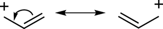
FIGURE 3-19: Pi bond resonance.
Similarly, when a lone pair of electrons is situated next to a positive charge, an alternative resonance structure involves moving the lone pair of electrons in the direction of the cation to form a double bond. The positive charge then moves to the atom that originally held the lone pair, because that atom has become deficient in electrons (see Figure 3-20).
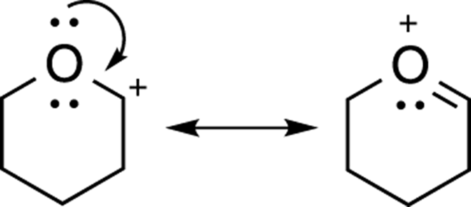
FIGURE 3-20: Lone pair resonance.
A double or triple bond containing an electronegative atom
When a double or triple bond includes an electronegative atom (like oxygen or nitrogen), an alternative resonance structure can be found by moving one of the double (or triple) bonds onto the electronegative element as a lone pair. In such situations, the electrons always go onto the more electronegative element, not the carbon. (Find out more about this rule in the “Assigning importance to resonance structures” section, later in this chapter.) An example of this kind of resonance is shown in Figure 3-21 for acetone (the chemical in nail polish remover).
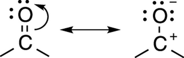
FIGURE 3-21: Pi bond resonance.
Alternating double bonds around a ring
When double bonds alternate all the way around a ring, you can move each of the double bonds over to the next carbon to make an alternative resonance form. Benzene, for example, has two resonance structures, as shown in Figure 3-22. Here you would break the octet rule if you were to stop after drawing either one or two of the arrows. So, you have to go all the way around the ring.
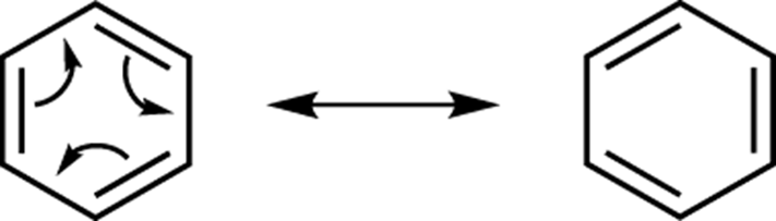
FIGURE 3-22: Benzene resonance structures.
Drawing more than two resonance structures
Sometimes a structure will have more than two resonance structures. Figure 3-23, for example, shows a molecule that has four resonance structures. If you were asked to draw all the resonance structures for this molecule, you would start by recognizing that the molecule had a double bond containing an electronegative atom, which conforms to pattern number three described in the preceding section.
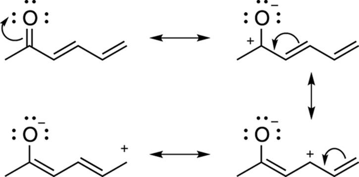
FIGURE 3-23: Four resonance structures for 2-hexadienone.
Drawing the resonance structure by moving the double-bond electrons onto the oxygen creates a species with a positive charge on carbon. But this is not the end of the resonance structures. This positive charge, now, is next to a double bond, which is another of the common patterns (pattern number two) discussed in the previous section. So, another resonance structure can be drawn by moving the double-bond electrons onto the single bond to the left, which moves the location of the positive charge. But there is still one more resonance structure that can be drawn. Moving the last double bond over to the left in the same fashion as you did previously puts the positive charge on the end carbon atom. All four of these structures are valid resonance structures and the actual structure looks like a hybrid of all of them.
Often, you can get to any of the resonance structures in a single step. Figure 3-24 illustrates this one-step process. Generally, though, drawing out all the resonance structures one at a time, as I’ve shown (at least until you get the hang of it), is helpful to make sure that you don’t leave out any resonance structures.
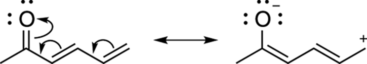
FIGURE 3-24: Converting between resonance structures in one step.
Assigning importance to resonance structures
Some resonance structures contribute more to the overall hybrid than others. As a rule, the more stable resonance structures will contribute more to the hybrid than unstable ones. Three major factors are used to determine the relative stability of resonance structures (and, therefore, their relative importance). In this section, I illustrate each of these three factors.
Fewest charges
The resonance structures that have the fewest charges within the molecule will contribute the most to the overall hybrid. This rule makes sense because keeping positive and negative charges separate from each other costs energy. For the molecule acetone, shown in Figure 3-25, the first resonance structure is uncharged, so it will contribute more to the overall hybrid than the resonance structure on the right that has both positive and negative charges.
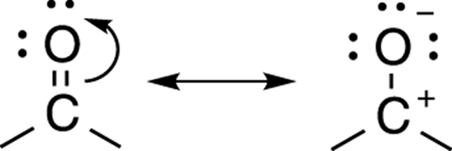
FIGURE 3-25: Acetone resonance structure.
Charges on the best atoms
Negative charges generally prefer to rest on electronegative elements (elements such as oxygen and nitrogen), while positive charges will prefer to rest on electropositive elements (such as carbon). An alternative resonance structure for acetone is one in which the negative charge rests on the carbon and the positive charge rests on the oxygen. This resonance structure is considered a bad resonance structure (see Figure 3-26). Because oxygen is an electronegative atom (an electron pig), it really does not want to have a positive charge; therefore, the resonance structure on the right would contribute an insignificant amount to the overall hybrid. Although technically it would be considered a valid resonance structure, this resonance form is never drawn because it’s so unstable that it would not significantly contribute to the overall hybrid.
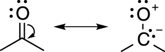
FIGURE 3-26: Bad resonance structure.
In the example shown in Figure 3-27, both resonance structures would contribute to the overall hybrid. In this example, the negative charge rests on either oxygen (in the right-hand structure) or carbon (in the left-hand structure). Because oxygen is more electronegative, the oxygen is more comfortable holding the negative charge than carbon is, so the resonance structure on the right would contribute more to the overall hybrid.
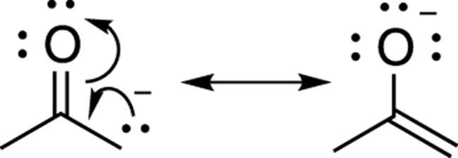
FIGURE 3-27: Comparing charge stability.
Filled octets
In the next example, shown in Figure 3-28, you may expect, based on the last argument about placing positive charges on electropositive atoms and negative charges on electronegative atoms, that the resonance structure on the left would contribute more to the overall hybrid, because carbon would be more willing to hold a positive charge than would nitrogen. However, this analysis neglects one key factor: a full octet of electrons.
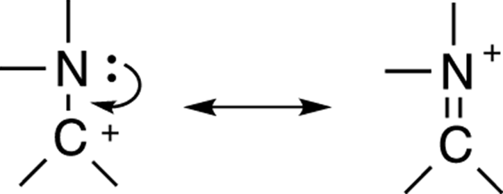
FIGURE 3-28: Octet considerations trump charge considerations.
In fact, the resonance structure on the right contributes the most to the overall hybrid, because every atom in that resonance form has a full octet of electrons. In the resonance structure on the left, the carbon does not have a complete octet, owning only six electrons in its outermost shell. Generally, the desire of atoms to achieve a full octet trumps the desire to put the charges on the best atoms. This is why the resonance structure on the right contributes more to the overall hybrid than does the resonance structure on the left, even though the structure on the right has the charge on a less preferable atom.
Common mistakes in drawing resonance structures
 Here are four common mistakes that students make in drawing resonance structures. Avoid these at all costs.
· Forgetting charges: After drawing out the arrows and determining what the alternative resonance structure will look like, leaving out a charge or two is an easy mistake to make (see Figure 3-29). One way to quickly check for missing charges is to see if all your charges balance. That is, the net charge that you begin with must equal the net charge that you end up with. If your starting resonance structure has a net negative charge, then all other resonance structures must have a net negative charge as well.
That’s not to say that the number of charges must be the same, just that the net charge must be the same. For example, if you start with no charges on a resonance structure, an alternative resonance structure can end up with one positive charge and one negative charge, because the net charge remains zero. But starting with a neutral molecule and ending up with one negative charge or one positive charge is not acceptable. If you see that your charges don’t balance, this generally indicates that you simply neglected to place a charge on one of the atoms.
· Breaking the octet rule: Breaking the octet rule is a fairly common mistake, and, unfortunately, it’s a big one. A general rule to remember is that an atom in the second row of the periodic table (like C, N, O, or F) will never have more than eight electrons around it. This means that the sum of all the bonds and lone pairs around one of these atoms cannot total more than four. I’ve known professors who have threatened to flunk students if on the final exam they drew a Texas carbon (a pentavalent carbon with five bonds, so called because everything’s bigger in Texas) like the one shown in Figure 3-30. So, avoid making this mistake.
· Moving single bonds: Resonance structures involve the movement of only lone-pair and pi electrons. Therefore, you can’t move single bonds. To do so would break up a molecule into fragments, as shown in Figure 3-31.
· Not following the electron flow: Electrons are always drawn “flowing” in a single direction. So arrows won’t start going one way and then double back in the opposite direction, as shown in Figure 3-32.
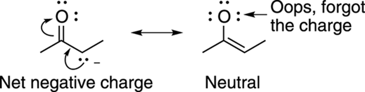
FIGURE 3-29: Keeping track of charges.
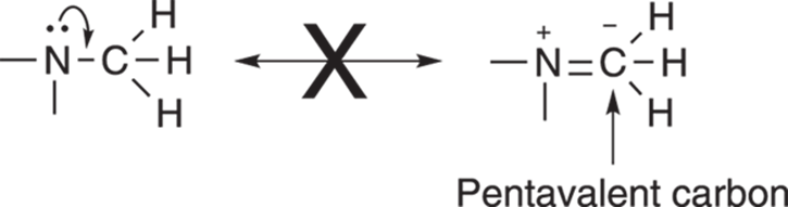
FIGURE 3-30: A Texas (pentavalent) carbon. A major organic chemistry no-no.
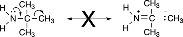
FIGURE 3-31: Single bond resonance — also a major no-no.
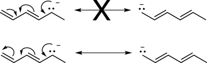
FIGURE 3-32: Resonance going against the flow.