Organic Chemistry: Concepts and Applications - Headley Allan D. 2020
Bonding and Structure of Organic Compounds
1.3 Chemical Bonds
Atoms combine with each other to form molecules, and the atoms in a molecule are held together by chemical bonds, which involve the valence electrons. There are two types of chemical bonds — ionic bonds and covalent bonds.
1.3.1 Ionic Bonds
For molecules that contain ionic bonds, the atoms involved acquire the electronic configuration of the nearest noble gas by either gaining or losing valence electrons. As a result, each atom of an ionic bond acquires a formal charge. Atoms that lose electrons acquire a positive formal charge and become cations, and atoms that gain electrons acquire a negative formal charge and become anions. The attraction that results between these two oppositely charged species (cation and anion) is called an ionic bond. Figure 1.8 shows the ionic bond that results between Li and F.
Note that in Figure 1.8, the lithium cation, which is formed after the loss of one electron, acquires the electronic configuration of the noble gas, helium (He). Similarly, fluorine acquires the electronic configuration of the nearest noble gas, neon (Ne), by gaining an electron. You will discover that ionic bonds are formed between atoms of the extreme columns of the periodic table. For example, the bond that is most likely formed between potassium and chlorine will be an ionic bond; similarly for sodium and bromine.
Problem 1.4
Using a formulism as that shown in Figure 1.8, illustrate how ionic bonds are formed between the following pairs of atoms.
1. Na and Cl
2. Li and Cl
3. Mg and F
1.3.2 Covalent Bonds
A covalent bond in a molecule results from the sharing of valence electrons of the atoms of that molecule. Among organic molecules, the covalent bond is the most common and this is the type of bond that you will encounter the most throughout this course. The valence electrons that are used to make a covalent bond are called bonding electrons, and valence electrons that are not involved in a covalent bond are called nonbonding electrons, or unshared electrons. The arrangements of the atoms and electrons (both bonding and nonbonding electrons) in molecules can also be represented using Lewis dot structures. As mentioned earlier, in the Lewis dot structure, only the valence electrons of an atom are considered, and recall that the valence electrons for a particular atom are the number of electrons that are contained in the orbitals that have the highest principal quantum number (outer shell). Thus, for carbon, the number of valence electrons is four (4) because there are a total of four (4) electrons in the 2s and 2p orbitals.
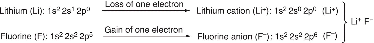
Figure 1.8 The formation of an ionic bond between lithium and fluorine.
In the Lewis dot structure of a covalent molecule, the valence electrons are represented by dots, with the bonding electrons located between the atoms, illustrating the covalent bond, and the nonbonding electrons located around the atoms of the molecule. The total number of valence electrons for a molecule is determined by adding the valence electrons of each atom of the molecule. In drawing Lewis dot structures, the octet rule is obeyed. The octet rule states that there must be a total of eight electrons (bonding and nonbonding) around each atom in a molecule. There are exceptions to this rule, however, and hydrogen is one exception that will be encountered frequently throughout this course. The number of electrons that are associated with a hydrogen atom in a molecule will not be eight, but two (2). Other atoms, such as boron (B), beryllium (Be), and aluminum (Al), are also exceptions, and they will be discussed later.
In order to draw the Lewis dot structure, the atoms of the molecule are typically arranged in the most symmetrical manner, and the first atom of the chemical formula is typically the central atom. The valence electrons are distributed so that each atom has an octet of electrons, except hydrogen, which has a duet of electrons. Since organic chemistry is the chemistry of carbon-containing compounds, it is extremely important that we fully understand how to draw the Lewis dot structure of compounds that contain carbons. Thus, we will start by looking at the simplest organic molecule, methane (CH4), the Lewis dot structure can be determined based on the number of valence electrons as shown below:
Atom |
# valence electrons in each atom |
Total # valence electrons |
Carbon (C) |
4 |
4 |
Hydrogen (H) |
1 |
(4 × 1) 4 |
Total valence electrons for CH4 = 8 electrons.
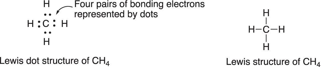
Note that in the Lewis dot structure of methane, the bonding electrons are represented by dots. Another representation of the same structure is to use a single line to represent a pair of bonding electrons that are shared between any two atoms. The representation of using a line to represent bonding electrons is very important since that will be the representation used throughout this course.
Another example of using the Lewis dot structure is shown below for carbon dioxide molecule (CO2).
Atom |
# valence electrons in each atom |
Total # valence electrons |
Carbon (C) |
4 |
4 |
Oxygen (O) |
6 |
(6 × 2) 12 |
Total valence electrons for CO2 = 16 electrons
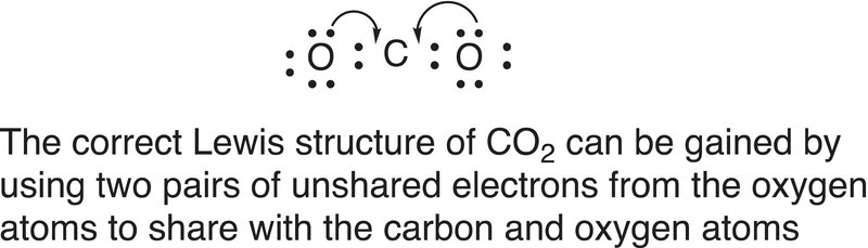
These 16 valence electrons must be distributed among the three atoms. One possibility is to try and distribute these 16 electrons so that each of the oxygen atoms gets an octet of electrons, as shown below.
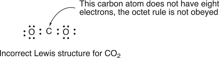
However, you will quickly realize that for this Lewis dot structure, the octet rule is not obeyed because the carbon does not have an octet of electrons, even though the oxygen atoms have an octet of electrons. As a result, this is not a correct Lewis dot structure for CO2, but it can be transformed into the correct Lewis dot structure by using two pairs of unshared electrons from the oxygen atoms to share with the carbon and oxygen atoms as shown below.
Note carefully that the curved arrow formulism is used to indicate the movement of electrons from the oxygen atom to form bonding electrons for the carbon and oxygen atoms. This method of using an arrow to show electron movement will be used routinely throughout this course. A double-barbed arrow is used to indicate the movement of two electrons (or a pair of electrons), and a single-barbed arrow is used to indicate the movement of one electron. Thus, the correct Lewis dot structure for carbon dioxide (CO2) is shown in Figure 1.9.
Note that the most symmetrical arrangement of the atoms results in a linear structure, in which the central atom, C, is the first atom of the chemical formula. Also, note that the bonds to carbon are double bonds. Thus, there are two double bonds in the carbon dioxide molecule and each oxygen atom has two pairs of unshared electrons.
Problem 1.5
Draw the Lewis dot structure for the following molecules and clearly show all nonbonding electrons.
H2O b) NH3 c) CS2 d) SiH4 e) CH2O f) CH2O2
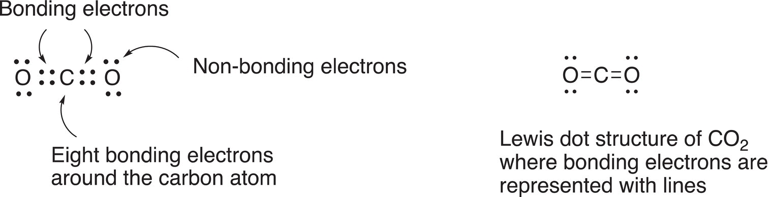
Figure 1.9 Correct Lewis dot structure for carbon dioxide (CO2).
1.3.3 Shapes of Molecules
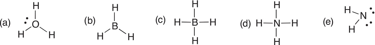
You saw from the example in the previous section that the geometry of CO2 is linear. This geometry results since electrons are negatively charged and are located at opposite ends of the molecule. Remember that like charges repel and opposite charges attract. Thus, the bonding electrons and the nonbonding electrons on oxygen are located at opposite ends of the molecule. For CH4, the geometry is different since there are now four pairs of bonding electrons, and as a result, the four hydrogens are located at opposite ends around the central carbon atom. This geometry is different from that of CO2 and is called a tetrahedral geometry. Remember that we should always be visualizing molecules in three dimensions. Valence shell electron pair repulsion (VSEPR) theory can be used to explain the geometry of CO2, CH4, and other molecules. This theory is based on the fact that electrons (bonding and nonbonding) have the same charge (negative), and as a result, will repel each other in a molecule. Thus, electrons (both bonding and nonbonding) of a molecule will be located at opposite ends of a molecule, which will result in different geometries around the central atom of different molecules. Figure 1.10 shows the geometries of some common molecules.
If there are only two electrons (one pair of electrons) between any two atoms in a molecule, the covalent bond is called a single bond. If there are four electrons (two pairs of electrons) between any two atoms as is the case with carbon and oxygen atoms of CO2, the bond is described as a double bond, and if there are six electrons (three pairs of electrons), the bond is called a triple bond.
Problem 1.6
Give the Lewis dot structure for the following molecules and predict the geometry about each atom of your structure that is bonded to at least two other atoms: NF3, H2S, CH4, CS2, CH2O, CH3OH, CH3N.
1.3.4 Bond Polarity and Polar Molecules
Because there are typically different types of atoms in a molecule, the bonding electrons between two different atoms in the molecule are not equally distributed within the bond. You will recall from your previous course in general chemistry that electronegativity is defined as the tendency of an atom to attract electrons toward itself and that the most electronegative atom is fluorine. The relative electronegativities of atoms can be determined from the periodic table. Electronegativity increases in going from left to right across a particular row of the periodic table and also increases in going up a particular group (column) on the periodic table. This means that electronegativity of different atoms increases in going diagonally toward fluorine on the periodic table. Thus, by using the periodic table, it is possible to determine relative electronegativities of any two atoms without knowledge of the actual electronegativity values.
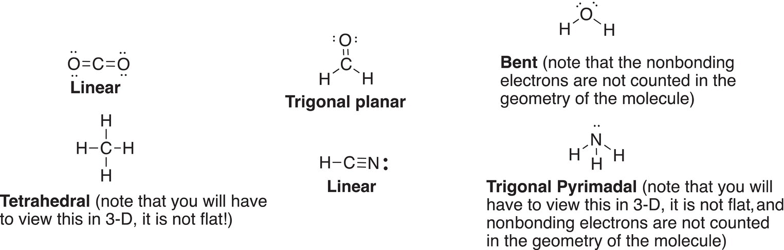
Figure 1.10 Examples of common organic molecules with different geometries as predicted by the VSEPR theory. Note that they also contain different types of covalent bonds, i.e. single, double, and triple covalent bonds.
Problem 1.7
Of the following pairs of atoms, look at the periodic table and determine which is more electronegative.
a) K and Br b) Cl and Br c) N and C d) Mg and C.
For some molecules, two atoms of a covalent bond (single, double, or triple) may have different electronegativities. Both atoms do not equally share the bonding electrons of such a bond. The more electronegative atom attracts the bonding electrons closer to itself, compared to the less electronegative atom. The relative electronegativities can be readily determined from the periodic table. Remember, the most electronegative atoms are located at the top right of the periodic table. Covalent bonds that have atoms of different electronegativities are called polar covalent bonds. On the other hand, if the electronegativities of both atoms in a covalent bond are the same, then the bonding electrons are shared equally and the covalent bond is called a nonpolar covalent bond. Thus, covalent bonds that involve atoms of equal electronegativity are classified as nonpolar covalent bonds.
Problem 1.8
Classify the following covalent bonds as polar or nonpolar.
a) O─H b) H─H c) HN═NH d) C─Mg e) C─O f) C─Cl
There are different ways to show the polarities of polar covalent bonds. The most commonly used representation in organic chemistry is the use of partial charges, δ+ or δ− (δ is the Greek letter delta, and the representations are referred to as delta negative and delta positive). The most electronegative atom gets the δ− symbol, and the least electronegative atom is assigned the δ+ symbol. The unequal distribution of bonding electrons for the polar bonding of H─Cl is shown in Figure 1.11. Also shown in Figure 1.11 is another representation of the distribution of the electrons of the polar covalent bond of H─Cl in which an arrow (with a cross) is used. For this representation, the head of the arrow points in the direction of the most electronegative atom and away from the least electronegative atom, as shown in Figure 1.11. Note that the very electronegative chlorine gets the δ− and the head of the arrow points to the chlorine atom. The most commonly used representation in organic chemistry is the use of partial charges, δ+ or δ−.
More examples in which these representations are used to show the polarities of polar covalent bonds are shown in Figure 1.12.
Problem 1.9
1. i) Give the Lewis dot structures of the molecules shown below and use the δ+ and δ− representations to indicate the polarity of the covalent bonds.
HF, HCN, NH3 and CS2.
2. Which of the following molecules have nonpolar covalent bonds?
H2, Cl2, CH3Cl, CO2, COS, and H2O.
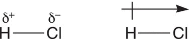
Figure 1.11 Two different representations of polar covalent bonds.
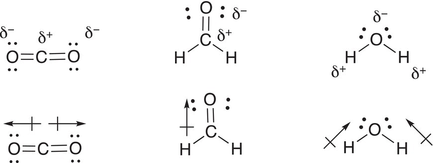
Figure 1.12 Examples of selected molecules in which different representations are used to show bond polarities.
Molecules that have at least one polar covalent bond may have a net molecular polarity based on the individual bond polarities; for example, hydrochloric acid is a polar molecule because there is a net dipole in the direction of the chlorine atom. For molecules with more than one polar bond, a carefully examination of the geometry of the molecule, along with the bond polarities, must be carried out in order to determine if the molecule is polar or not polar. The dipole moment of molecules is determined by the sum of the bond polarities and the three-dimensional geometry of the molecule. For example, water as shown in Figure 1.12 is a polar molecule since the bond dipoles do not cancel each other, but instead reinforce each other. On the other hand, carbon dioxide, as shown in Figure 1.12, is linear and since the two atoms bonded to the central carbon are the same (oxygen atoms) and bonded to the central carbon atom at a bond angle of 180o, carbon dioxide is not a polar molecule. The dipole moment is a measure of the overall polarity of a molecule, and the Greek letter μ is used to represent dipole moments of molecules. A close analysis of molecules must be carried out in order to determine if they are polar molecules or not. An analysis of the polarity of each covalent bond, along with an analysis of the three-dimension geometry of the molecule, must be carried out. For example, CO2 has two polar C═O double bonds, but the molecule is linear and the two bond dipoles of equal magnitude point in opposite directions. As a result, the bond dipoles cancel, and the net dipole of the molecule is zero. On the other hand, H2O, which is a bent molecule, has a dipole moment greater than zero (μ > 0).
Problem 1.10
Draw the Lewis dot structures of each of the following molecules; determine the geometries and which have dipole moments of zero or nonzero.
a) CH4 b) CHCl3 c) H2O d) CS2 e) NH3 f) CH2Cl2 g) COS h) BF3
1.3.5 Formal Charges
The atoms of some molecules have charges, even though the overall charge of the molecule may be neutral. For most molecules that will be encountered in organic chemistry, the charge on most of the atoms is zero, but for some molecules, atoms may acquire a formal charge of +1 or −1 or even higher charges. The classic example of a molecule that is neutral, but has atoms with formal charges, is nitric acid and the Lewis dot structure is shown in Figure 1.13.
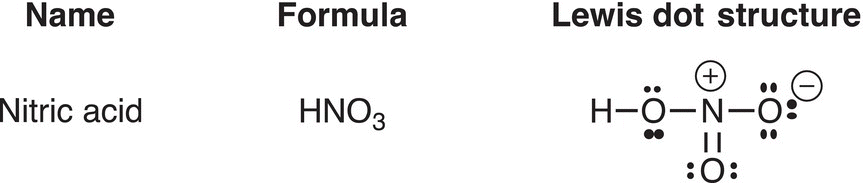
Figure 1.13 Lewis dot structure of nitric acid showing the formal charges.
Shown below are different equations that are used to calculate the formal charge for a specific atom in a molecule.
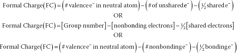
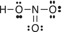
In order to determine the formal charge of an atom in a molecule, the Lewis dot structure of the molecule must first be determined. For example, the formal charge of nitrogen in the Lewis dot structure of nitric acid (HNO3) shown in Figure 1.13 is +1. This value can be obtained by first drawing the Lewis dot structure of nitric acid, as shown below; then by using one of the above equations the formal charge can be calculated, as shown in Eq. (1-3).
(1-3)![]()
Similarly, the formal charge of one of the oxygen atoms (oxygen at the top right) as shown in Figure 1.13 is −1 and below is shown the calculation to obtain its formal charge as shown in Eq. (1-4).
(1-4)![]()
The formal charge calculation shows that the formal charge of the other oxygen atom (oxygen at the bottom) is zero as shown in Eq. (1-5).
(1-5)![]()
Problem 1.11
Utilize one of the equations above to calculate the formal charge for the central atom of each of the following species.
1.3.6 Resonance
For some molecules or ions, it is possible to draw more than one Lewis dot structures that meet the requirements of the octet rule. For example, nitric acid has two equivalent Lewis dot structures. Such equivalent Lewis dot structures are also called resonance structures, and the double-headed arrow is used to show this relationship between resonance structures as shown in Figure 1.14.
Since electrons are in constant motion in specific regions of space, resonance structures result from the movement of electrons (typically of unshared electrons or electrons of a double or triple bond) across bonds or atoms within the molecule. Resonance structures (or equivalent Lewis dot structures) are possible only for molecules or ions that have double and triple bonds or at least one lone pair of electrons that are adjacent to each other. Equivalent Lewis dot structures can be achieved by a method called curved-arrow formulism in which arrows are used to show the movements of electrons, as shown below.
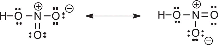
Figure 1.14 Equivalent Lewis dot structures (resonance structures) for nitric acid.
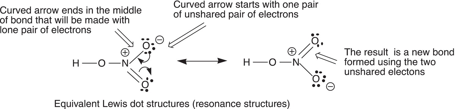
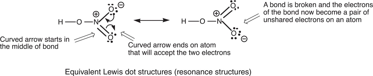
Note that the curved arrow starts with one pair of electrons and ends in the middle of the bond that will be made with these two electrons. The other curved arrow movement starts in the middle of the double bond and shows how the electrons are moved onto the electronegative oxygen to give another resonance structure. Note that a double-headed arrow is used and each barb of the arrow represents an electron. There will be the need in later chapters to move just one electron at a time and then a single-barbed curved arrow is used to indicate the movement of just one electron. This curved-arrow formulism will be used frequently throughout this course to obtain different resonance structures and to show the movement of electrons in general.
Nitric acid is just one example where resonance structures are possible, there are many other molecules and ions that will be encountered throughout the course. In this section, different types of molecules and ions that have possible resonance structures will be discussed. The first example is shown in the resonance structures given in 1-6.
(1-6)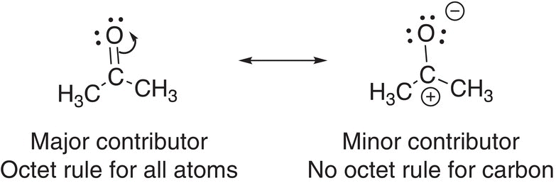
Note carefully that a curved double-headed arrow is used in the resonance structure to the left to indicate the electron movement of two electrons of the double-bonded electrons to the more electronegative oxygen. A close examination of the resonance structures shown above reveals that the atoms of the resonance structure of the left all have an octet of electrons; whereas, for the resonance structure on the right, the carbon atom does not have an octet of electrons. As a result, the resonance structure on the left is described as contributing more to the overall picture of the molecule and is a major contributor to the overall structure of the molecule. The other resonance structure is considered to be a minor resonance contributor to the overall resonance structure of the molecule shown.
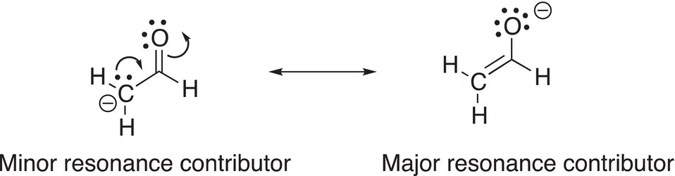
For resonance structures in which all the atoms have an octet of electrons, there may be other factors to consider in determining the major and minor resonance contributors. For the anion shown below, all the atoms have an octet of electrons, but in the resonance structure to the left, there is a negative formal charge on carbon, which is not as electronegative as oxygen. On the other hand, the resonance structure on the right has the negative formal charge on the more electronegative oxygen atom. Thus, the resonance structure to the left is the minor resonance contributor, and the structure to the right is a major resonance contributor.
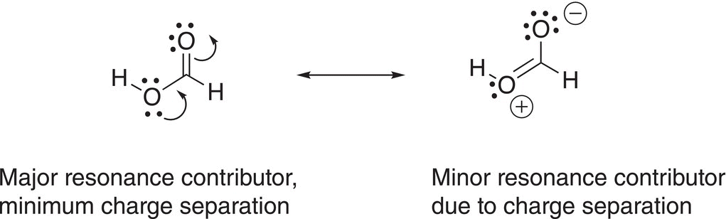
In determining major resonance contributors, the charge separation must also be considered. For the resonance structures shown below, the resonance structure to the left is neutral with no charge separation; whereas, the structure to the right, even though it is neutral, there is a charge separation. As a result, the resonance structure to the left is a major resonance contributor, since there is minimum charge separation, actually zero, and the resonance structure to the right is minor, since there is a charge separation.
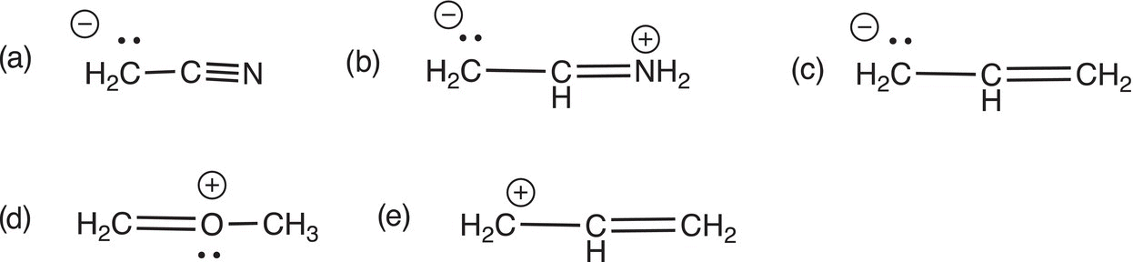
Problem 1.12
1. i)Use curved arrow formulism to show electron movement. Show how the resonance structure on the left is transformed to the resonance structures on the right.
2. ii)Give another resonance structure for each of the following species. Use curved arrow formulism to indicate electron movement and include formal charges where appropriate.