Physical Chemistry Essentials - Hofmann A. 2018
The Chemical Bond
11.7 Valence Bond Theory and Hybridisation of Atomic Orbitals
The valence bond (VB) approach considers the overlap of the half-filled valence atomic orbitals of each atom containing one unpaired electron, thereby assuming that all bonds are localised bonds. This approach builds on the Lewis structures of molecules which have been introduced in introductory chemistry courses. Historically, the VB theory is a further development of the Lewis structures that also accounts for the geometric shape of molecules. Its main advantage is indeed the description of molecular shapes, but shortcomings remain in the correct prediction of electronic structures in some cases (e.g. molecular oxygen, O2). However, despite those deficits, the VB method is still frequently used in qualitative descriptions of bond formation in molecules.
Conceptually, the VB method assumes that due to the spatial closeness of the electrons and nuclei of two atoms engaging in a bond, their orbitals become distorted as a consequence of the electrostatic interactions. Therefore, these orbitals no longer adopt their pure forms but rather a mix of the features of the pure orbitals; the resulting orbitals are thus called hybrid orbitals. Importantly, the mixing must not be confused with the linear combination of atomic orbitals in Sect. 11.3.2 which resulted in molecular orbitals. The hybrid orbitals are still atomic orbitals, since they arise from a single atom.
11.7.1 Hybridisation of Atomic Orbitals
To illustrate the concept, we consider methane (CH4). All experimental studies show that the four C—H bonds in methane are identical in length and energy; the four hydrogen atoms are indistinguishable and the molecule possesses tetrahedral symmetry, resulting in the angle of 109.5° between any pair of C—H bonds. Recalling the three-dimensional arrangements of the 2s and the three 2p orbitals, it is obvious that the tetrahedral symmetry cannot be explained by overlap of those ’pure’ atomic orbitals with the four 1s orbitals of the hydrogen atoms. Since four identical bonds require four identical orbitals, one can suggest four identical atomic orbitals which may be derived from one s and three p orbitals by mixing them into four hybrid orbitals (sp 3) that extend into the four directions of a tetrahedron. The mathematical representation of the mixing is given in Table 11.4. Each sp 3 orbital has the same shape (see Fig. 11.13) and its direction is determined by the signs. The C—H bonds are now accomplished by overlap of the four 1s orbitals of the hydrogen atoms with the four sp 3 hybrid orbitals of carbon (see Fig. 11.14).
Table 11.4
Mixing rules of to obtain hybrid from pure atomic orbitals. There are as many hybrid orbitals as pure orbitals used for mixing
|
Hybrid orbital |
Mixing of atomic orbitals |
Topology |
Angle between hybrid orbitals |
sp |
|
linear |
180° |
sp 2 |
|
planar |
120° |
sp 3 |
|
tetrahedral |
109.5° |

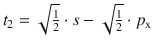
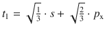
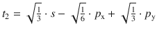
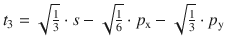
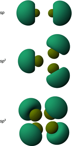
Fig. 11.13
Shapes and directions of sp, sp 2 and sp 3 hybrid orbitals obtained by mixing pure s and p orbitals as specified in Table 11.4
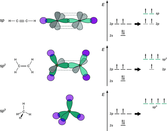
Fig. 11.14
Schematic illustration of bond formation in acetylene, ethylene and methane. The hybrid atomic orbitals of carbon are coloured turquoise, the 2p orbitals grey and the 1s orbitals of hydrogen are coloured magenta
Schematic drawings such as the one in Fig. 11.14 qualitatively depict the shape of atomic orbitals and frequently used in pen-and-paper discussions of the binding situation in molecules.
In contrast to methane, ethylene (C2H4) is a planar molecule. The angle between two C—H bonds is 120°, which can be explained by the formation of three sp 2 hybrid orbitals from the 2s and two 2p orbitals (for example, p x and p y; see Fig. 11.13 and Table 11.4) of carbon, each occupied with one electron, ready to pair up with the one electron in a bonding orbital provided by another atom (2× 1s orbital of hydrogen and 1× sp 2 hybrid orbital from the other carbon; see Fig. 11.14). The fourth remaining electron occupies a pure ’left-over’ p orbital; since p x and p y have been mixed, the remaining pure p orbital is p z. Overlap of the two p z orbitals of the two neighbouring carbon atoms provides a further bond, in addition to the bond arising from overlap of two sp 2 hybrid orbitals. Earlier (Sect. 11.3.2), we have introduced the distinction between electron density arising between atoms on the inter-nuclear axis (σ bond) and above/below or in front/behind the inter-nuclear axis (π bond). As illustrated in Fig. 11.14, the overlap of the pure p orbitals in ethylene occurs above and below the C—C axis and therefore constitutes a π bond.
Bonding in the linear acetylene (C2H2) molecule can be explained by mixing of the 2s and one 2p orbital of carbon, resulting in the formation of two sp hybrid orbitals (see Fig. 11.13 and Table 11.4). As illustrated in Fig. 11.14, the sp orbitals of the two neighbouring carbon atoms overlap on the inter-nuclear axis and thus form a σ bond. The second sp hydrid orbital on each of the carbon atoms overlaps with the 1s orbital of the hydrogen atoms, forming another σ bond. The remaining pure p orbitals p y and p z on each of the neighbouring carbon atoms also possess one electron each and overlap above/below (p z) and in front/behind (p y) of the inter-nuclear axis and therefore give rise to two π bonds.
11.7.2 Valence Shell Electron Pair Repulsion
The hybridisation of atomic orbitals can be successfully applied to many molecules comprising of covalent bonds. In ammonia (NH3), for example, one might think that due to the electronic configuration of 1s 2 2s 2 2p 3 of nitrogen the three hydrogen atoms might be bound by overlap of the three 2p orbitals of nitrogen (with one electron each) with the 1s orbitals of the hydrogen atoms (also one electron each). This would result in an angle of 90° between any two N—H bonds. However, experimentally, the angle between two N—H bonds is observed with 107.3°.
Alternatively, we can consider formation of four sp 3 hybrid orbitals on the nitrogen; three of those hybrid orbitals are occupied by one electron and overlap with the hydrogen 1s orbitals. The fourth sp 3 hybrid orbital is populated with two electrons of anti-parallel spin and forms a so-called lone pair. Repulsion between the lone pair electrons and the electrons in the N—H σ bonds ’pushes’ the three N—H bonds closer together and thus causes a decrease of the expected bond angle from 109.5° to 107.3°. This concept forms the central idea of the so-called valence shell electron pair repulsion ( VSEPR).
The repulsive effect is more pronounced in the presence of more electrons. For example, in the water (H2O) molecule, the bond angle between the two O—H bonds is 104.5° and therefore even further decreased from tetragonal angle of 109.5°. With oxygen having an electron configuration of 1s 2 2s 2 2p 4, the orbitals of the second shell can again hybridise to form four sp 3 hybrid orbitals. However, two of those hybrid orbitals are occupied by two electrons each, thus forming two lone pairs which exert a stronger repulsive effect towards the electrons in the σ bonds than the one lone pair in the case of ammonia.
The VSEPR approach remains a popular method for qualitative description of covalent bonding in for lighter elements, but does not predict correct geometry for some compound groups involving heavier elements (such as e.g. calcium, strontium and barium halides).
11.7.3 Resonance Structures and Electron Delocalisation
Both the molecular orbital (MO) theory and the valence bond (VB) theory are useful approaches to describe chemical bonding. One aspect of the VB method that is very appealing to many chemists is the fact that it allows depiction of molecules in connectivity diagrams which remains the by far most frequently used method to denote molecular structures.
However, it is often impossible to denote the properties of particular molecules with a single structure. The most prominent example is certainly benzene (C6H6) for which a cyclic structure was first proposed by Kekulé in 1865. A ring structure can be accomplished with 6 · 4 = 24 carbon valence electrons, if one assumes three alternating double bonds (see Fig. 11.15). Such a structure would require that there are two types of C—C bond lengths in the ring: 1.54 Å for a single, and 1.33 Å for a double bond. In contrast, the experimentally determined C—C bond length in benzene is 1.40 Å. We realise that the assignment of the C—C double bond in the ring is entire arbitrary and can formally suggest a second structure where the double bonds are localised differently. More realistically, though, the molecule resonates between the two depicted structures which depict two possible extremes. The possible extreme structures are those we can depict with localised bonds and are called resonance structures. In the depiction of such structures, a double-headed arrow is used to indicate that the structure(s) shown are indeed resonance structures.
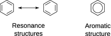
Fig. 11.15
Depiction of resonance and aromatic structures of benzene
Aromaticity
Cyclic planar molecules that possess increased chemical stability when compared to linear molecules with the same number of atoms are called aromatic compounds. The increased stability is a direct consequence of the electron delocalisation within the molecule, i.e. the existence of resonance structures.
The properties of aromatic systems include:
✵ Delocalised π electrons, typically a result of alternating single and double bonds
✵ Coplanar structure
✵ Atoms are part of one or more ring systems
✵ Hückel’s rule: the number of π electrons is 4 · N + 2, with N = 0, 1, 2, …
When depicting chemical structures, the existence of aromaticity is often shown as a circular bond (see Fig. 11.15).
Resonance structures arise when the valence bond method is used to describe molecules; this is typically the case when constructing connectivity diagrams such as in Fig. 11.15. An alternative explanation for phenomena such as aromaticity is provided by the molecular orbital (MO) theory. Focussing on the π electron system, we need to consider the six p z orbitals which need to be combined in accordance with the linear combination of atomic orbitals. Therefore, six different linear combinations of the wave functions of the six p z orbitals have to be generated. This results in three bonding and three anti-bonding molecular orbitals. The phase distribution in the different molecular orbitals are indicated in Fig. 11.16 by colours and the boundaries define the nodal planes. The (bonding) MO with the lowest energy shows that these electrons are delocalised over the entire ring. With increasing energy, the number of nodal planes increase and thus the compartmentalisation of the orbitals. Electrons populating the higher energy MOs are therefore increasingly localised.
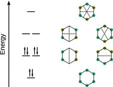
Fig. 11.16
The molecular orbitals and schematic representation of wave functions of the π system of benzene