Physical Chemistry Essentials - Hofmann A. 2018
Interactions of Matter with Radiation
13.5 Spectroscopic Methods Involving X-rays
13.5.1 Photoelectron Spectroscopy
In Sect. 8.1.3 we discussed the photoelectric effect that described the release of electrons from a metal plate that is exposed to electromagnetic radiation (Fig. 8.3). From Einstein’s frequency law (Eq. 8.8) it became clear that the energy of the incident light (h·ν) equals the work required to release electrons from the material (h·νcath) and the kinetic energy of the released electrons (½·me·v 2):
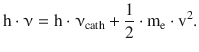
(8.8)
This photoelectric effect can also be observed with non-metals, and the frequency law is then formulated more generally as
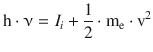
(13.38)
where, according to Koopman’s theorem, I i is the ionisation energy, i.e. the energy required to expel an electron from a particular orbital i.
This effect forms the basis of photoelectron spectroscopy where light of a particular wavelength (monochromatic light) is directed onto a sample and the kinetic energy of released photoelectrons is determined. Energy measurements of electrons require conditions of very high vacuum; therefore, fairly sophisticated equipment as well as careful sample preparation is required for such experiments. The choice of light source depends on whether photoelectrons originating from valence orbitals (with low ionisation energies) or such from deeper orbitals (with high ionisation energies) are investigated. For the former, UV light available e.g. from helium gas discharge lamps is used; this is known as UV photoelectron spectroscopy ( UPS). Spectra obtained from UPS show peaks that correspond to the ionisation energies of the valence orbitals, but also a fine structure due to vibrational levels of the molecular ion, which facilitates the assignment of peaks to bonding, non-bonding or anti-bonding molecular orbitals.
Photoelectrons originating from core orbitals require higher energies in the X-ray region. These types of experiments are known as X-ray photoelectron spectroscopy ( XPS). In contrast to valence electrons, the electrons in core orbitals of an atom should not be affected by neighbouring atoms. At a first approximation, XP spectra of a particular element therefore show peaks at the same energy irrespective of whether it exists as an isolated atom in the gas phase, covalently bonded in a molecule or embedded in a solid. XP spectra are therefore ideal to determine the elemental composition of samples (a technique known as electron spectroscopy for chemical analysis, ESCA).
Closer inspection shows that the type of bonding does have a small effect on the position of the core photoelectrons in XP spectra and small shifts are seen when comparing the same element in varying bonding environments.
13.5.2 X-ray Diffraction
When discussing the scattering of light by atoms and molecules in previous sections (e.g. such as in the case of Raman spectroscopy), we very much focussed on the scattering by single isolated molecules. When atoms and molecules are arranged in a periodic array with long-range order, the superposition of light scattering from individual atoms gives rise to the phenomenon of diffraction, due to constructive interference of waves at particular angles.
The scattering of light arises from the interaction of electromagnetic radiation with matter which causes the electrons in the exposed sample to oscillate. The accelerated electrons, in turn, will emit radiation of the same frequency as the incident radiation ( secondary waves). In a crystalline sample, the individual atoms can be considered point scatterers which all emit secondary waves. The strength with which an atom scatters light is proportional to the number of electrons around that atom. Upon superposition of individual secondary waves, the phenomenon of interference occurs. Depending on the displacement (phase difference) between two waves, their amplitudes either reinforce or cancel each other out. The maximum reinforcement is called constructive interference, the cancelling is called destructive interference. The interference gives rise to dark and bright rings, lines, or spots, depending on the geometry of the object causing the diffraction. Diffraction effects increase as the physical dimension of the diffracting object ( aperture) approaches the wavelength of the radiation. When the aperture has a periodic structure, for example in a diffraction grating, repetitive layers or crystal lattices, the features generally become sharper.
Constructive interference of secondary waves from point scatterers occurs only when the diffraction condition is met. Using a geometric approach (Fig. 13.23), the father-son team of William Henry and William Lawrence Bragg found that the diffraction condition is met for re-radiated waves that enclose an angle of 2·θ with the incident beam of monochromatic radiation (i.e. single wavelength), if the path difference is equal to an integer multiple of the wavelength (Bragg and Bragg 1913). The diffraction condition is known as Bragg’s law:
![]()
(13.39)
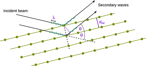
Fig. 13.23
Geometric construction to explain the Bragg diffraction
From the observed diffraction rings (powder/multi-crystalline samples) or spots (mono-crystalline samples) that appear at a particular angle 2·θ with respect to the incident beam, one can therefore calculate distances of lattice planes (d) via the geometric relationship with the integer multiples (n) of the wavelength λ.
Since the distances between atoms or ions are at the order of 10−10 m (1 Å), diffraction methods used to determine structures at the atomic level require radiation in the X-ray region of the electromagnetic spectrum, or beams of electrons or neutrons with a similar wavelength. We recall from Sect. 8.1.5, that electrons (as well as neutrons) are particles, but also possess wave properties with the wavelength depending on their energy ( DeBroglie relationship). Accordingly, diffraction can not only be observed X-rays but also electron and neutron beams.
Crystalline materials are characterised by the long-range order/periodic arrangement of atoms. The unit cell of a crystal is the basic repeating unit that defines the crystal structure. It repeats in all three dimensions and thus defines the lattice parameters of the crystal. Parallel planes of atoms intersecting the coordinate system of the unit cell define directions and distances in the crystal. The different sets of parallel planes are characterised by their intercepts with the axes of the coordinate system (defined by the unit cell). The reciprocal fractional intercepts are called the Miller indices (h with x-axis, k with y-axis and l with the z-axis), which together with the distance d hkl between the parallel planes in the set, describe a particular set of planes that elicits a diffraction spot at the angle 2·θ.
Notably, in contrast to the definition of resolution in optical microscopy (see Sect. 8.1.5), the resolution of structures derived by diffraction methods is the smallest distance d hkl of lattice planes (corresponding to the maximum reflection angle θ) that can be resolved on the diffraction image.
13.5.3 Mößbauer Spectroscopy
Similar to the resonance phenomena discussed in earlier sections of this chapter, there is a phenomenon of nuclear resonance of γ-rays. If a particular nucleus with Z protons (= order number) and N neutrons exists in an excited state of the energy level E exc , it can transition into the ground state with the energy level E ground and emit the energy difference as a photon; due to the magnitude of the energy difference
![]()
the photon will be a γ-ray. If this photon hits another nucleus of the same element, that second nucleus can transition from the ground into the excited state. As we have seen earlier, such resonance phenomena are possible only if the incident photon possesses exactly the same energy that corresponds to the difference between the energy levels of the excited and the ground states.
However, similar to a gun, the excited nucleus experiences a recoil effect when emitting a γ-ray photon, owing to the conservation of the total momentum. The recoil effect results in the nucleus to be kicked back, in the direction opposite to the emitted photon. Since the principle of conservation of energy still needs to be considered, too, the emitted photon possesses an energy that is slightly less than the energy difference between the ground and excited states of the transitioning nucleus; the energy of the recoil effect needs to be subtracted from the energy difference between the two nuclear states:
![]()
(13.40)
The recoil energy of a free atom or molecule can be calculated as per
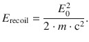
(13.41)
Since the energy E 0 takes substantial values (due to the photons being γ-rays), the recoil energy E recoil is orders of magnitudes larger than the natural line width of a transition. The emitted photon thus carries less energy than the resonance difference E 0 (Eq. 13.40) and this difference cannot be ignored; this is different with electromagnetic radiation of lesser energies where the recoil energies are less than the natural line widths, and the recoil effect thus does not play a significant role.
As the absorbing nucleus also experiences a recoil effect as it receives the incoming photon, for a successful resonance transition to occur the energy of the incoming photon needs to carry not only the resonance energy E 0, but also the energy to compensate for the recoil effect:
![]()
(13.42)
The energies of emitted and received photons are therefore separated by 2·E recoil (Eqs. 13.40, 13.41) and, due to the large value of E recoil with respect to the natural line width, do not overlap (Fig. 13.24). It is thus virtually impossible to observe this resonance phenomenon in the gas or liquid phase.
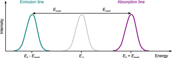
Fig. 13.24
The γ-ray emission and absorption lines observed with free atoms do not appear at the theoretical energy E 0 but are shifted to higher/lower energies due to the recoil effect. In order for the resonance condition to be met in the absorption case, the incoming γ-ray needs to possess a higher energy than the difference between the two atomic energy levels in order to account for the additional energy when transferring momentum (recoil). For emitted photons, the energy of the γ-ray is decreased by the amount of the recoil energy
However, Rudolf Mößbauer discovered in 1958 that in the crystalline phase the crystal lattice is able to absorb the recoil energy and thus allows the observation of nuclear resonance (Mößbauer 1958). This is called the Mößbauer effect, which led to award of a Nobel prize to his discoverer in 1961; the criterion for it to occur is generally formulated as
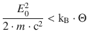
(13.43)
whereby Θ is a measure for the strength of the crystal lattice (the so-called Debye temperature). For a given temperature the probability of a successful nuclear resonance to occur is higher the stronger atoms are embedded in a crystal. At lower temperatures, the probability of recoil-free emission and absorption of photons increases.
In a Mößbauer spectrometer, the resonance absorption of emitted photons due to nuclear transitions is disturbed in a controlled fashion by varying the energies of the incoming photons. This is achieved by mounting the emitter of the photons (source) on a drive that moves the source with constant velocity either towards or away from the sample (absorber). Due to the externally controlled velocity, the emitted photons experience an additional momentum ( Doppler effect) and their energy is thus higher or lower than the transition energy E 0.
If the velocity of the moving source is varied from zero to a maximum value, then the resonance condition is only met at zero velocity and the overlap of the emission and the absorption lines decreases as the photons emitted by the source are subject to significant Doppler shifts and their energies thus deviate from E 0. Since the detector in a Mößbauer spectrometer acquires the transmittance of photons through the sample (absorber), the maximum signal is registered in the regions outside the resonance condition and the lowest transmittance is registered when the resonance condition is met exactly (see Fig. 13.25).
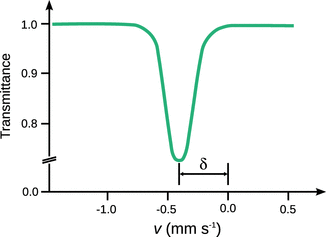
Fig. 13.25
Mößbauer spectra are recorded as relative transmission which is the ratio of γ-quant counts in the resonance range and the number of counts in the non-resonance range. This results in a resonance curve with lowest transmission at the velocity of the source that exactly meets the resonance condition. The isomeric shift δ is defined as the offset to zero velocity
The number and position of resonance lines in Mößbauer spectra depend on the interactions between nuclei as well as the electric and magnetic fields experienced by the nuclei. These fields are dominated by electrons in the valence shell which define many chemical and physical properties of substances. Three parameters of Mößbauer spectra can be used to assess the interactions between nuclei (see Table 13.7):
✵ isomeric shift
✵ electric quadrupole splitting
✵ magnetic splitting.
Table 13.7
Summary of the main parameters observed in Mößbauer spectra of substances in solid phase
|
Parameter |
Type of interaction |
Description |
Isomeric shift |
Interaction between nucleus and electrons |
Reminiscent of the chemical shift observed in NMR. Information about the absorber: ✵ oxidation state ✵ binding properties of complexes ✵ electronegativity of ligands |
Quadrupole splitting |
Interaction of the nuclear quadrupole momentum and the electric field at the nucleus |
Only possible for nuclei with a spin I > ½; results in (I + ½) sub-levels. Information about the absorber: ✵ spin state ✵ oxidation state ✵ molecular symmetry ✵ binding properties, magnetic behaviour |
Magnetic splitting |
Interaction between the nuclear magnetic momentum and the magnetic field at the nucleus |
Only possible for nuclei with a spin I > 0; results in (2·I + 1) sub-levels. Reminiscent of the hyperfine splitting ( Zeeman effect) observed in EPR. Information about the absorber: ✵ spin state ✵ oxidation state ✵ molecular symmetry ✵ binding properties, magnetic behaviour |
Suitable nuclei for Mößbauer spectrometry include Fe, Ni, Zn, Ru, Ag as well as all elements of the third transition metal row, and most lanthanide and actinide metals.