Process Technology: An Introduction - Haan A.B. 2015
4 Chemical reactors and their industrial applications
4.3 Tubular reactors
4.3.1 Introduction
Most industrial applications of tubular reactors involve homogeneous gas— and liquid phase reactions. In these applications, a tubular flow reactor is chosen when the reactor is to operate continuously but without back-mixing of reactants and products. In the ideal tubular reactor the fluids flow as if they were solids, plugs, or pistons. Thus in the idealized tubular reactor all elements of fluid take the same time to pass through the reactor and experience the same sequence of temperature, pressure, and composition changes. In practice there is always some degree of departure from the ideal plug-flow condition. The most serious are departures from a uniform temperature profile across the radius of the reactor. There will be local variations in reaction rate and therefore in the composition of the reaction mixture. Flow in tubular reactors can be laminar or turbulent. Generally, turbulent flow is preferred to laminar flow, because mixing and heat transfer are improved and less back-mixing is introduced in the direction of flow.
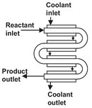
Fig. 4.10: Schematic of a tubular reactor.
When heat transfer to the reactor is required, a configuration with a high surface-to-volume ratio is employed (Fig. 4.10). In such reactors the reaction volume is made up from a number of tubes, which can be arranged parallel or in series. The parallel arrangement gives a lower velocity of the fluid in the tubes, which results in a lower pressure drop, but also in a lower heat-transfer coefficient. It is very suitable to use a second fluid outside the tubes for heat transfer. On the other hand, with tubes in series, a high fluid velocity is obtained inside the tubes and a higher heat transfer coefficient results. The series arrangement is therefore often more suitable if heat transfer is by radiation or when the main resistance to heat transfer is located inside the tube. From this it is clear that a tubular reactor has the advantage of favorable conditions for temperature control through heat supply or removal. Another important advantage is the lack of moving mechanical parts, which makes tubular reactors especially suitable for high-pressure service. Due to their length and relatively high velocities, high pressure drops are usually encountered. The flexibility of tubular reactors is limited, because they are in most cases designed for a specific application with a high degree of specialization.
4.3.2 Gas-phase reactors
Production of olefins by the steam cracking of hydrocarbons such as naphtha provides an excellent example of the use of tubular reactors for an important petrochemical process (Fig. 4.11). The reaction is highly endothermic, and the highest selectivity toward the desired olefinic products is achieved at short residence times with temperatures up to 900 °C. Despite the name steam cracking the reactions do not involve steam. The role of steam is to lower the hydrocarbon partial pressure in the reactor to enhance the olefin yield. Other functions of steam are aiding heat transfer from the reactor wall and reaction with coke deposits on the reactor walls to reduce coke formation. The cracking of hydrocarbons occurs almost entirely by homogeneous gas-phase free-radical chain reactions. In the simplest case, ethane pyrolysis, the steps can be set out as follows:
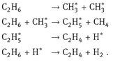
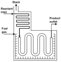
Fig. 4.11: Schematic representation of a steam cracker furnace.
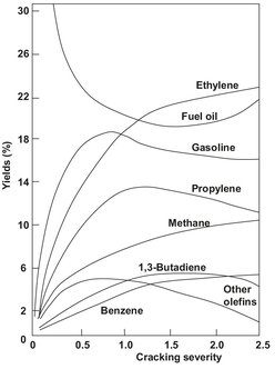
Fig. 4.12: Effect of cracking severity on product gas composition.
Besides these reactions, several hundreds of other reactions take place, yielding a large variety of other hydrocarbon products. Chemical simulation models that can simulate more than a hundred different species and several thousands of different chemical reactions are used to optimize the product distribution of large-scale steam crackers. The main objective is to maximize the yield to ethylene and propylene for each type of naphtha. As illustrated in Fig. 4.12, this can be accomplished by optimizing the cracking severity, which is a combination of cracking temperature and residence time. Typically the product gas from a naphtha steam cracker contains about 30 % ethylene and 14 % propylene.
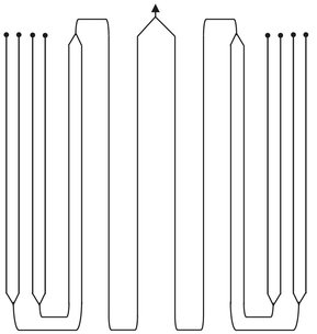
Fig. 4.13: Example of steam cracker reactor geometry giving improved heat transfer and lower pressure drop.
Since rapid heating to reaction temperature is required and the reaction is highly endothermic, it must be carried out in a tube reactor with a high surface-to-volume ratio. In the earliest tubular furnaces the internal diameters of the reactor coils were usually uniform. The introduction of new steel alloys allowed the construction of more complex reactor coils that have the advantage of better heat transfer and lower pressure drop. In these reactor coils the first one or two passes are made from a tube of smaller diameter. The resulting larger surface-to-volume ratio allows higher heat inputs, and as a result the full cracking temperature is reached more rapidly. In a typical arrangement four parallel 50 mm tubes are followed by two 75 mm tubes and then a single 100 mm tube (Fig. 4.13). Several of such coils are combined in a single firebox and are directly heated by natural gas burners. Virtually all of the heat transfer to the outside of the tubes occurs by radiation from the hot combustion gases.
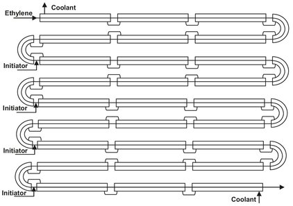
Fig. 4.14: Schematic drawing of high pressure tubular reactor for polyethylene (LDPE) production.
4.3.3 Liquid-phase reactors
LDPE (low-density polyethylene) is produced by polymerization of ethylene at pressures between 1500 and 3500 bar. These extreme operating conditions and the high heat of polymerization are good reasons for using a tubular reactor. The reactors typically consist of 1000 to 2000 meters of jacketed high-pressure tubing (Fig. 4.14). Such a reactor is constructed from a large number of sections, each 10 m long, which are arranged in the shape of an elongated coil. Inner diameters range typically between 50 and 75 mm, depending on the capacity of the system. A ratio of outer to inner diameters of about 2.5 is used to provide the necessary strength for the high pressures involved.
In the first section of the reactor the compressed ethylene is preheated to the temperature at which polymerization is initiated. This temperature depends on the initiator employed and ranges from 140 to 180 °C. After introduction of the peroxide initiator, the temperature of the reaction mixture rises to a peak of 300-350 °C and is then cooled back down to about 250 °C (Fig. 4.15). The ethylene velocity must be at least 10 m/s to provide sufficient heat transfer and reduce fouling of the reactor wall. In general the reactor is long enough to provide more than one reaction zone, and the polymerization is reinitiated. This is repeated 3 to 4 times until conversions between 30 and 40 % are obtained.
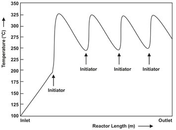
Fig. 4.15: Typical temperature profile in a high-pressure polyethylene tubular reactor.