Process Technology: An Introduction - Haan A.B. 2015
15 Product technology
15.4 Polymer processing
Depending on the shape desired and the dimensions of the product, a large variety of techniques are available for shaping the polymer end product. By outlining a selection of the techniques, we hope to convey some idea of the broad scope of polymer processing. However, because of space limitations only the processes that use extruders as the initial step will be discussed.
15.4.1 Extrusion processes
Profile extrusion is the direct manufacture of shaped products such as rods, strips, profiles, and sections from the extruder die. Hollow sections include a circular tube and pipe, square tube for racking and light furniture, and complex hollow sections such as window framing. In continuous operation, extrusion would produce a very long object with a shape determined by the die used in the process. Therefore additional operations are required to deliver a fully satisfactory product. With the use of a cutter at the end of the cooling section, objects of well-defined lengths can be produced. Pull rolls are used to assist transporting the shape through the cooling section to the cutter and can also be used to stretch the shape or fiber before it solidifies. For example, grains are produced by extruding a fiber of relatively high thickness and cutting it in very small pieces. A complete setup for (industrial) extrusion is given in Fig. 15.18.
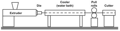
Fig. 15.18: Extrusion setup.
In profile extrusion the shape and dimensions of the die determine the shape of the final product: a circular opening results in a solid fiber. However, due to the effect of die swell, the design of dies for extrusion processes is never an easy task. Die swell is the effect where the polymer expands as soon as it leaves the die. The result is an extrudate which differs in its dimensions from those of the die orifice. Thus an extruded rod would have a larger diameter, and a pipe would have thicker walls. Die swell is the combined result of the elastic component in the overall response of a polymer melt to stress and the pressure difference between the extruder and the surroundings. It results from recovery of the elastic deformation as the extrudate leaves the constraint of the die channel and before it freezes. Therefore, the size of the die is never equal to the size of the resulting fiber, and even the shape of the die can differ from the shape of the desired product. Fig. 15.19 shows a square die with the resulting product-shape and a die with the resulting square product. For similar reasons the die dimensions only approximately determine the pipe dimensions. In pipe extrusion it is common to apply some “drawdown” to pull the extrudate away from the die exit and counteract the swell. If more exact pipe dimensions are required, a sizing mandrel is used. If an exact inner diameter is required, the extruded pipe is passed over a mandrel of the appropriate size. When the outer diameter is specified, an external sizing device is required. Two basic versions exist. In one the pipe is pressurized against the external mandrel by air injection, while in the other a vacuum outside the mandrel allows the normal atmospheric pressure inside the pipe to hold it against the mandrel.
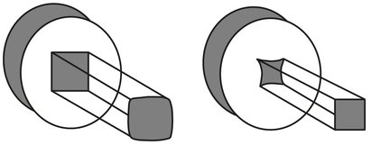
Fig. 15.19: Different die shapes with corresponding product shapes.
A derivation of the conventional profile extruder is that in which the melt turns 90° before emerging from its die. This is used in electrical cable manufacture where polymer insulation, often polyethylene, is applied to electrical conductors by this means. Fig. 15.20 shows this process schematically. The wire is pulled through the coating head of the extruder by the haul-off gear of the plant. The molten polymer enters at right angles and is forced around the cable by the die pressure. The wire takes along the polymer coating, the thickness of which depends on the balance between the polymer flow rate and wire speed. A typical single wire may consist of a copper conductor 0.45 mm in diameter with an insulating covering LDPE 0.22 mm thick produced with extrusion rates in excess of 1500 m/min.
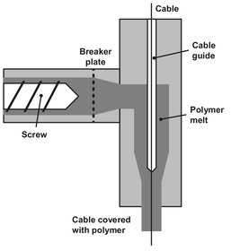
Fig. 15.20: Cable covering by cross-head extrusion.
15.4.2 Injection and blow molding
Two different types of molding are used in commercial processes: injection molding and blow molding. In injection molding a batch of molten polymer is injected under pressure into a steel mold. After the plastic solidifies, the mold is opened, and the product is removed from the mold. This can be done either by gravity or by ejector pins. An injection-molding machine consists of an injection unit and a clamp unit which houses the mold. This basic layout of an injection-molding machine is shown schematically in Fig. 15.21. In the first section the process is virtually the same as in an extrusion process. The main difference is that the screw is displaced rearwards as it pumps melt into the reservoir formed by the injection cylinder. An additional complication is that the screw can run intermittently and reciprocate, piston like, within the barrel to act as the ram for injection. The sequence of operations in the injection-molding process starts with an empty closed mould and a shot of melt ready in the injection unit. Injection occurs by opening the valve, and the screw forces the melt through the nozzle into the mold. Pressure is maintained during the early stages of cooling to counteract contraction. Once cooling progresses, the pressure is released by closing the valve, and the screw rotation restarted. Pressure develops against the closed-off nozzle and the screw moves backwards to accumulate a fresh shot of melt in the front. Meanwhile, the melt in the mould has continued to cool, the press and the mold open, and the molding is removed. Finally the mold closes again and the cycle repeats. A large proportion of the total cycle time is taken by cooling, including the hold-on time. As a consequence, cooling rates are an important concern in the economics of injection molding.
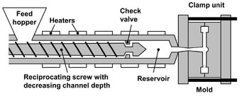
Fig. 15.21: Schematic of an injection-molding machine.
The mold contains the cavity in which the molded product forms, the channels along which the melt flows as it is injected, cooling channels through which cooling water is pumped, and ejector pins which remove the molding from the cavity. Molds are custom made and polished to a very high gloss, because every detail of the mold will be visible in the finished product. Usually a full shot, as it is called, is not completely used. Often a sprue, runner, and gate are present, as can be seen from Fig. 15.22. These are separated from the desired part and fed back to the injection unit, where they are melted and used in the process again. The mold is mechanically fastened in the clamp unit, but is interchangeable to allow different products to be molded. The clamp unit is essentially a press closed by a hydraulic or mechanical toggle system. The clamping force available to it must be great enough to resist the force generated by the melt as it is injected. The pressure in this melt can be in excess of 1000 bar, so that for moldings with a large projected area the force required can be as high as several thousand tons.
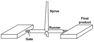
Fig. 15.22: Injection-molded product.
Blow molding is the established technique for producing bottles and other hollow objects. There are two major subcategories: extrusion blow molding and injection blow molding. In extrusion blow molding the resin is used directly from the extruder, and the process takes place in four steps, as can be seen from Fig. 15.23. In the first step an extruder runs continuously to produce parisons at a single crosshead die. The mold moves to the die and closes on a length of parison, sealing one end. A parison cutter separates it from the die, and the mold moves away from the die to allow extrusion of the next parison to continue. The mold arrives at the blowing/cooling station, where a blow-pin is inserted into the open end of the parison and seals it. Compressed air is fed through the blow pin into the parison, inflating it against the inside of the cooled mold surfaces. The bottom of the bottle is formed by the “pinch-off” of the mold, and a characteristic of blow-molded plastic bottles is the scar caused by this mold closure weld. Once the molding has sufficiently solidified, the product is recovered by opening the mold, and the molding cycle begins again. Although the extrusion process may be intermittent, the continuous arrangement, where the parison is cut off and moved away in the mold, is the most widely used, because it allows higher production rates.
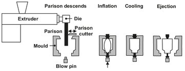
Fig. 15.23: Extrusion blow molding.
Injection blow molding has emerged in recent years as a major method for the production of PET bottles for carbonated drinks. It differs from extrusion blow molding by using an injection-molded preform instead of a directly extruded parison. The tube is first extruded and quenched rapidly to prevent crystallization of the PET. Next the tube is heated to just above its glass transition temperature, usually 90—100 °C, and stretchblown. As can be seen from Fig. 15.24, the stretch blowing is accomplished by pushing down the blow-pin to stretch the preform downwards and simultaneous blowing to give radial expansion. The actual blowing introduces a circumferential orientation that results in a rapid crystallization and solidification of the PET.
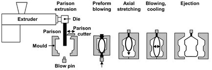
Fig. 15.24: Stages in injection blow molding.
15.4.3 Melt and gel spinning
Many synthetic fibers are produced by extrusion through fine holes, a process known as melt spinning. Although melt spinning is the most economical spinning process, it can only be applied to polymers that are stable at temperatures sufficiently above their melting point, such as nylon, polyester, polyethylene, and polypropylene. Most meltspinning plants melt the polymer with the aid of screw extruders, which can be fed directly with the solid polymer grains and forward molten polymer of high melt viscosity (Fig. 15.25). The polymer melt is extruded under pressure through a spinneret, which is a flat plate made of stainless steel containing orifices. The number of holes may range from a few to several thousand, with individual hole diameters in the range of 175—750 µm. The feed rate to individual spinning units is controlled by an accurately machined metering gear pump, which delivers molten polymer at a constant rate into a filter assembly. As molten polymer passes through the spinneret, the emerging bundle of fibers is quenched in water or a countercurrent flow of air, under a high draw-down rate. Usually the product obtained from the spinning process is not directly suitable for commercial use. The fibers are then further cold-drawn as they pass to the wind-up, to orientate the molecules and develop the necessary linear strength. The dimensions of the produced filament or yarn are expressed in the unit called tex. This measure of fineness or linear density is defined as 1 g/1000 m. The filament linear density is related to its diameter by
![]()
(15.4)
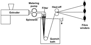
Fig. 15.25: Melt spinning of fibers.
The linear density is controlled by the throughput of polymer per hole, W (kg/s), and the windup speed, V (m/s). The melt-spun filament linear density (tex) is then
![]()
(15.5)
DSM’s high strength fiber, Dyneema®, required a new method for its production. Its strength is due to the orientation of the polymer molecules in the fiber, they are all parallel to the length of the fiber. Melt spinning cannot be used in this case because of the very high melt viscosity of the ultrahigh molecular weight polyethylene (UHMW-PE). In order to be able to use the desired polymer, a new process called gel spinning was developed. An additional advantage of the use of a solvent is that the degree of entanglement in the polymer decreases. This is especially true if dilute solutions are used. With this reduced degree of entanglement, it is a lot easier to achieve a highly oriented polymer in the final fiber and a higher degree of orientation is achieved.
Gel spinning is essentially a two-step process. First a fiber is spun from a solution of the polymer, and after that the fiber is stretched and dried. For the production of Dyneema®, a dilute solution of 1-2 % of polyethylene (PE) in an organic solvent is used for spinning the fibers at 150 °C. A typical solvent is decalin, a higher aromatic compound, yielding fibers with good mechanical properties. The polyethylene used has an ultrahigh molecular weight of around 1-4 · 106, which is one of the reasons why a high strength fiber results. The spinneret used in this process has openings with diameters of 0.5—2 mm, depending on the desired fiber diameter. The fibers are quenched to room temperature in a water bath and a disoriented gel fiber remains. The solvent content of the fiber has to be at least 50 %, and can be as high as 98 %, which has to be completely removed to produce a strong homogeneous fiber. This is done by increasing the temperature to 50 °C prior to stretching. At this stage the molecules are still disoriented, and the fiber does not have a high strength. Next, the fiber is stretched further, and the temperature is gradually increased from 120 to 160 °C. Now orientation of the polymer takes place, and the fiber attains its great strength. The remainder of the solvent also evaporates in this stage. It is carried by a hot gas and can be recycled after cooling and/or cleaning. A schematic overview of the gel-spinning process is given in Fig. 15.26.
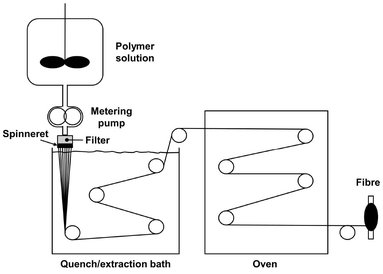
Fig. 15.26: Gel-spinning process.
15.4.4 Film production techniques
Polymeric films can be produced by calendering, extrusion, casting, and blowing. Calenders are used for making rubber sheeting and similar products from plasticized PVC and ABS with variable thicknesses less than 1 mm. The process requires the polymer to be in the rubbery state and concerns the production of sheet of accurate thickness by passing the compound between rotating rolls. Often, more than one nip is required to give a sheet of the required accuracy, in which case multiroll machines are then used. The rolls are often placed in an inverted L-configuration, which can be recognized in the typical layout of a calendering plant shown in Fig. 15.27. The rolls tend to bend because of the pressure, and this has to be taken into account when designing them. They are also equipped with cooling channels to control the temperature during processing. Each roll is driven separately by a variable-speed drive. The first sheet is formed at the first nip directly from the feed, which may be supplied from a two-roll mill or extruder. The second gap usually allows the sheet through without nipping. The sheet is then remade at the third gap, where a thin “pencil” bank is kept rolling. Calenders are mainly used for resins with high melt viscosity, which results in high pressures on the rolls. Under good conditions the thickness of the sheet can be controlled to ± 0.02 mm.
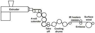
Fig. 15.27: Calendering plant containing an inverted L four-roll configuration.
Film and sheet can also be produced by direct extrusion in a similar way as shown in Fig. 15.28. Thicknesses below about 0.5 mm are usually called film, and above 0.5 mm sheet. As widths between 1 and 2 m are frequently required, the design of dies for the production of sheet or film presents certain challenges. The requirement is to deform the melt from its essentially cylindrical shape to a wide thin form and obtain uniform distribution of the polymer melt across the die.
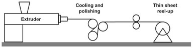
Fig. 15.28: Sheet extrusion.
In casting the film is extruded directly on to a roll through a long straight slit with an adjustable gap in the order of 0.4 mm (Fig. 15.29). The die is positioned very carefully with respect to the casting roll, which is used for controlled cooling and to impart some degree of drawdown to enhance the film properties by orientation and reduce the film thickness. The cooling roll is highly polished to achieve a smooth and flawless surface of the film produced. Usually, the die for cast film is deflected downwards to effect the best approach to the casting rolls. Since the web of resin narrows as it is drawn from the die, the die is wider than the desired film. The edges of the film are removed because of thickening during the process. The edge trim can be recycled if desired. The process of extrusion coating is similar. The film emerging from the die contacts the substrate to be coated at a nip, and the resulting laminate proceeds around a cooling train to the wind-up. Cardboard coated in this way is extensively used for foodstuffs.
Widely used for the productions of thin films from LDPE, HDPE, PP, and PET is the tubular-blown film process. Blown film is made by extruding the polymer melt through an annular die, producing a tube that is inflated with air and yielding a bubble of the desired diameter and which is at the same time drawn upwards. The result is that the produced film becomes biaxially orientated, and this orientation is made permanent by the crystallization that freezes the orientation in place. The blown tube is cooled and solidified by blowing air upwards along the outside of the expanded tube and guided by converging boards or sets of roller onto the nip rollers (Fig. 15.30). It may be wound directly as a flat tube or slit at both sides and wound into two flat reels. Extrusion is usually vertically upward to avoid buoyancy effects on the blown tube, permitting the heavy extruder and winds-ups to be floor mounted.
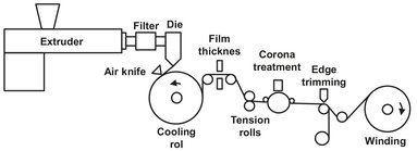
Fig. 15.29: Film extrusion.
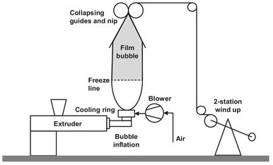
Fig. 15.30: Diagram of the tubular-blown film extrusion process.
The minimum thickness of a film which can be produced on a continuous basis without a lot of rejected films depends on the viscosity of the polymer used. In Fig. 15.31 a schematic representation of the minimum thickness dependency of PE-films on the melt index is given. The melt index can be regarded as the reciprocal value of the meltviscosity at a constant shear stress. As can be seen, the minimum thickness generally decreases with an increasing melt index. Exceptions are resins (a) and (c), both representing another important factor in film casting: the molecular weight distribution. Resin (c) has a broad distribution, which results in better flow characteristics, whereas (a) has a narrow distribution, resulting in worse flow characteristics.
For a polymers that run well in this process, such as polyethylenes (HDPE, LDPE), the produced bubble is stabilized by the tension stiffening of the polymer melt and a favorable also tension-induced crystallization rate. An interesting contrast exists in the production of polypropylene film. Polypropylene is tension-thinning in the melt, and also its crystallization rate during cooling is rather slow. A different technique is adopted in which the extrudate is quenched from the melt with ice water to give a rubbery amorphous tube. This tube is then reheated to the temperature at which crystallization is at its maximum and blown. Blowing the reheated tube avoids the problems associated with a tension-thinning melt and a slow crystallization rate, which would result in an unstable bubble. This process for polypropylene differs further from polyethylene in that it is run vertically downwards.
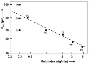
Fig. 15.31: Minimum thickness of PE films.
15.4.5 Thermoforming
Thermoforming refers to a group of processes that involve clamping a sheet of thermoplastic above an open mold, heating it so that it becomes soft and rubbery and then forcing the sheet to take up the contours of the mold, where it cools and solidifies. The deformation of the sheet is achieved either by applying mechanical force or compressed air to the top of the sheet (pressure forming), or by drawing a vacuum between the sheet and the mold (vacuum forming). This processing method uses relatively low pressures and temperatures, because high temperatures would result in a polymer that is not self-supporting. In principle a product can be made by the two different molds shown in Fig. 15.32. The female mould uses a cavity for the main formation, whereas the male mould uses a projection.
As can be seen from the lower part of the figure, this type of thermoforming produces a product with nonuniform thickness. This is due to contact chilling of the polymer, which results in excessive thinning of the parts of the sheet that contact the mold last. A relatively easy adjustment to the process, especially in vacuum forming, can be made to achieve a product with a more uniform thickness. Simply blowing a bubble of the sheet before applying a vacuum does this. This way the sheet is pre-stretched to the desired dimensions and in the actual forming stage, and the thickness of the sheet remains intact.
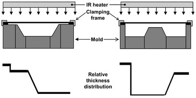
Fig. 15.32: Female (left) and male (right) thermoforming molds.
Thermoformed products are mainly of a relatively simple geometry, most being thin-walled panels, trays, cups, and boxes, of various shapes and sizes. Advantages of this technique are its low capital cost, low molding pressure, and reasonably short cycle times. For small series or research purposes, it is even possible to make the mold out of wood. Balanced against these advantages are a number of disadvantages, among which are the limited product geometry and the difficulty in obtaining a narrow thickness distribution. Plastics used for thermoforming are usually resins that have rubber-like properties over a wide temperature-range, mostly the amorphous polymers. Examples include polystyrene, ABS, PVC and polycarbonate (all amorphous) and significant quantities of semicrystalline HDPE and PP.
15.4.6 Foam extrusion
Foamed sheets are an important product for thermal insulation, packaging, and cushioning. They are produced by extrusion under carefully controlled conditions. Cylindrical shapes are extruded for pipe insulation. The foams are formed by the action of gas-producing blowing agents that are mixed into the polymer melt. These agents may consist of low boiling solvents, azo compounds that release nitrogen, or isocyanates that release carbon dioxide. Owing to the high pressure, the blowing agent remains dissolved until pressure is reduced at the die exit and instantaneous foaming occurs. Foaming requires fairly constant output for control of the product density and close control of temperature to achieve the correct degree of decomposition of the foaming agent. Critical to the success of most foaming extrusion operations are good mixing within the extruder and cooling of the melt just prior to entry of the die to prevent premature release of the blowing agent and control the density and surface finish of the sheet. Cooling is most effectively accomplished with a tandem arrangement of two extruders, as shown in Fig. 15.33. The first extruder assures complete dissolution of the blowing agent, and the second extruder is operated at slow speed for optimum cooling.
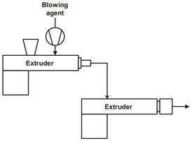
Fig. 15.33: Foam extrusion line.
Nomenclature
A, B |
screw geometry |
[m2] |
d |
filament diameter |
[m] |
L |
filled length |
[m] |
N |
screw speed |
[ms—1] |
P |
pressure |
[Pa] |
Q |
flow |
[m2 s—1] |
R |
remission value |
[%] |
T |
temperature |
[K] |
V |
windup speed |
[m s—1] |
W |
throughput per hole |
[kg s—1] |
η |
melt viscosity |
[Pa · s] |