Process Technology: An Introduction - Haan A.B. 2015
Appendices
Base chemicals
A.1 Ammonia
A.1.1 General description
In this chapter the conversion of natural gas to ammonia is discussed. Natural gas mainly consists of methane CH4, which is the actual reactant. The overall reaction, takes place according to
![]()
(A.1)
As with most processes, this reaction is not carried out in one step. First the natural gas has to be desulphurized, and steam is added. Next, the methane is thermally cracked to hydrogen, CO, and CO2, and in a second step the majority of the CO is converted to CO2. After removal of the COX the hydrogen is dried, and a reaction with nitrogen takes place to produce the ammonia, which is cooled and purified. The corresponding flow sheet is given in Fig. A.1.
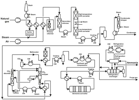
Fig. A.1: Flow sheet of an ammonia plant. Adapted from [213].
A.1.2 Desulphurization
The supplied natural gas contains some sulphur (as H2S and COS), which is a catalyst poison. To remove this contamination hydrogen is added and in the presence of a NiO catalyst, almost all of the sulphur is converted to H2S and absorbed on NiO, which is converted to NiS. After some time the catalyst bed has to be replaced, because all the NiO is consumed. For large amounts of sulphur removal an acid gas absorption stripper system is used for bulk removal and after that the described NiO system is used.
A.1.3 Primary and secondary reforming
The purified natural gas, which contains about 80 % methane, is converted to hydrogen and CO, as given in eqs. (A.2a) and (A.2b). The latter is called the water-gas shift reaction:
![]()
(A.2a)
![]()
(A.2b)
Both of these reactions are endothermic, which means that a lot of heat is required to allow these reactions take place. High temperature, low pressure, and high steam-to-carbon ratios favor the reactions.
In the primary reformer the feed of methane and steam is led through nickel alloy tubes and placed in a furnace to heat the gas to 750—850°C at a pressure of 30-40 atmosphere. The nickel content of the alloy, which also acts as a catalyst, is in the range of 20—30 %. Most of the methane is converted, but there is still a large amount of CO in the outlet gas. Side reactions taking place are carbon formation by decomposition of higher hydrocarbons and by CO reduction and disproportionation. Most of this takes place in the first section of the reformer, when the hydrogen content is still low. Promoters, such as potash, are used to suppress the carbon formation, which decreases the cracking of higher hydrocarbons. The reformer type used is a so-called Kellogg box type. In the box reformer the catalyst tubes are arranged in parallel, single-width rows heated from both sides, either by gas or liquid fired burners, located in the furnace arch.
In the secondary reformer the reaction is continued at higher temperatures (up to 1000 °C) to achieve a low methane slip (0.2—0.3 vol%). Again the catalyst used is nickel, this time on an alumina support to withstand the high temperatures.
A.1.4 Shift conversion
Because the ammonia synthesis catalyst is very sensitive for poisoning by CO and CO2, these gases have to be removed. The easiest way to do this is to convert the carbon monoxide to carbon dioxide, absorbing the dioxide with a suitable absorbent. Unfortunately, the conversion of CO leads to equilibrium. At 300 °C, only 85 % conversion is obtained, which even decreases at higher temperatures. Usually the conversion is separated into two parts: a high temperature conversion (HTS) to remove the bulk of the CO, and a low temperature conversion (LTS) for the remainder. The HTS takes place at 350-400 °C over a magnetite catalyst stabilized with chromium oxide. The main reason to apply high temperatures is the high reaction speed, so the conversion of the bulk of the CO2 takes place very rapidly. The LTS converter operates at temperatures of 200-250 °C in the presence of a CuO catalyst supported on alumina and zinc oxide. The converter design is based on an already used catalyst system, so that when the catalyst load is fresh (and thereby more active), the operating temperature can be lower than design temperatures. Gradually raising the temperature compensates for the lower activity of the used catalyst, and thus a constant outlet composition is achieved.
A.1.5 Carbon dioxide removal
Carbon dioxide is an acidic gas which reacts reversibly with aqueous solutions of alkanol amines. In general, solutions of weak bases (15-40 wt%) in water are applied for the removal of CO2 from gases. Strong bases are inapplicable, because they would give irreversible absorption. The most used solvent is methyl-di-ethanol-amine (MDEA), and the CO2 content can be lowered to 50 ppm. In most processes absorption is effected between 20 and 40 °C in countercurrent operation in a column, preferably at the highest possible pressure. The amount of nonacid gas components absorbed is so small that the quantity released upon pressure reduction is too small to return them to the absorber; moreover, expansion turbines cannot be applied here. The regeneration is carried out at atmospheric pressure by applying heat. Since much water is removed from the solution along with desorbed CO2, it is customary to cool the top product of the regeneratorwith a cooler/condenser and return the water to the column as reflux. A simple flow sheet of this absorption stripper system is given in Fig. A.2.
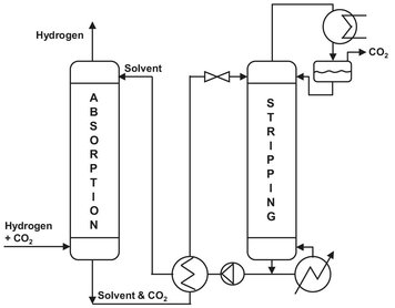
Fig. A.2: CO2 removal system.
A.1.6 Final purification
Because oxygen containing compounds poison the ammonia syntheses catalyst, they must be efficiently removed. This is done in three steps: methanation, dehydration, and excess nitrogen removal. The reactions taking place in the methanation are exactly the reverse of the reforming reactions at a temperature of 300—400 °C. They almost go to completion, reducing the CO and CO2 content to a few ppm. Dehydration is done by the use of molecular sieves, usually at the interstage of the syntheses gas compressorto reduce volume requirement. Excess nitrogen removal is necessary because there are some processes which use excess air (and thus excess nitrogen), and the nitrogen has a negative influence on the ammonia production. This is usually carried out by cryogenic purification, which involves cooling and stripping of the partly liquefied stream. Even here the CO content is lowered, about 50 %
A.1.7 Ammonia syntheses and recovery
The purified gas consists mainly of hydrogen and nitrogen (with a molar ratio of 3:1) and some inerts like argon methane and sometimes helium. As can be seen from eq. (A.3), the reaction will lead to an equilibrium, and therefore not all of the raw material can be converted. A higher conversion can be reached by introducing a recycling loop. The exact recycling stream in proportion to the product stream has to be determined after economic considerations. After mixing with the recycling loop, compression takes place to 220 bar and a temperature of 500 °C. By doing this the speed of the reaction is increased and the equilibrium is shifted to a more favorable ammonia production. As previously discussed, the syngas is dried at this stage using molecular sieves, after which the ammonia from the recycle is recovered. This reduces the required refrigeration, because the converter effluent is not saturated by the syngas addition, and cooling water can be used instead of more complicated refrigeration methods. This method leads to a very pure syngas, which increases catalyst lifetime (even up to 20 years) due to the lack of contaminants. To maintain a high partial pressure of the reactants, the inerts entering with the syngas have to be removed using a purge stream, as will be discussed later on:
![]()
(A.3)
The actual reaction takes place in an ammonia converter (see Fig. A.3) in which the gas flows through three adiabatic fixed beds, and part of the heat of reaction is utilized to generate steam in the two intermediate heat exchangers. Most of the conversion takes place in the first bed, which has the highest driving force to equilibrium. The gas mixture is cooled, and the excess heat is used to produce steam (40 bar) and heating up the H2/N2-mixture before entering the converter. For structural reasons the heat exchanger is incorporated between the inflow and outflow in the lowest part of the pressure casing. The reaction gas then flows upward in the annular gap between the pressure casing and the fixed beds, whereby it is further heated and at the same time protects the pressure-bearing structural components against excessively high fixed-bed temperatures to prevent hydrogen embrittlement.
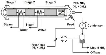
Fig. A.3: Schematic of a multistage ammonia converter. Adapted from [213].
The mixture now enters the recycling loop, from which the ammonia is recovered. This is done by cooling the mixture to about 6 °C, from which the liquid ammonia is removed. The remaining gas is heated and enters the converter again, together with the fresh feed. The purge stream is lead through a postconverter, in which the remaining hydrogen and nitrogen is converted to ammonia. Again, the mixture is cooled to remove the ammonia. The remaining gas is purged.
A.2 Inorganic acids
In almost all chemical processes acids are needed, either as raw material or as a catalyst. Two of the most widely used are nitric acid and sulfuric acid. If a company has a high acid consumption, it might be economically attractive to install production plants of its own.
A.2.1 Nitric acid
Almost all commercial processes are based on the oxidation of ammonia to nitrogen oxide, which in turn is reacted with water to form nitric acid. The overall reaction taking place is
![]()
(A.4)
Historically, different design philosophies between the United States and Europe have led to the development of two basic types of weak acid plants: the high monopressure and the dual pressure processes. The high monopressure process has been favored in the US because of its lower capital cost and the traditionally lower energy and ammonia prices there. In Europe the dual-pressure process is the most commonly used (see Fig. A.4).
The ammonia, which is supplied at a 16 bar pressure, is vaporized at 6 bar and heated to 45 °C. Impurities like oil and water are removed by a purge, and the ammonia is led through a candle filter where impurities larger then 3 microns are removed. Air is passed through a filter and compressed to 5.2 bar, and temperatures can rise up to 220 °C. After compression the air is split into two streams: a primary stream for ammonia incineration, and a secondary stream for oxidation of NO. The compressor is powered by the energy recovery from the expansion of the spent process gasses, which are expanded from 10 bar to almost atmospheric pressure. Ammonia and primary air are then mixed in a 9:1 ratio and directed to the burners.
The ammonia/air mixture is passed over a platinum/rhodium (95/5%) gauze to produce nitric oxide, water vapor, and a great deal of heat. The resulting gasses are cooled, thus producing 79 bar steam and heating the off-gasses. The steam is used to power the compressor. The initial catalyst gauzes contain smooth wires, and after some time catalyst migration takes place, resulting in a rough surface. Due to the increased surface area the ammonia, conversion increases at first, but a gradual decline with time is observed because of catalyst loss. Because the amount of precious metal lost is financially significant, glass fiber filters or palladium catchment gauzes are used to recover lost catalyst particles.
As the gasses produced are cooled further to 50 °C, the nitric oxide is oxidized to nitrogen dioxide. The water formed condenses at this stage, and together with part of the NO2 it forms a 35 wt% nitric acid solution. Because hot liquid nitric acid is very corrosive, expensive materials are needed which are resistant to corrosion by hot acid. The remaining gas is mixed with the secondary air and compressed further to 10 bar. Temperature is increased by this procedure to 170 °C. The steam needed to drive the compressor is generated completely in the plant itself. After cooling in two separate heat exchangers, the temperature is decreased to about 50 °C, and 65 wt% nitric acid is formed, which is fed to the absorption tower.
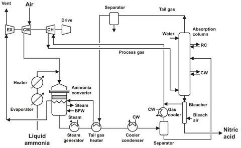
Fig. A.4: Dual-pressure process flowsheet. Adapted from [212].
In the absorption tower, process gasses are brought in contact with water in a countercurrent flow. The NO2 is absorbed, and the NO is oxidized with the remaining oxygen to form NO2. Typical dimensions are a diameter of 6 m, a height of 70 m, and a number of trays ranging from 30 to 50. The heat generated by the oxidation is removed using internal cooling spirals. The acid produced is led through a rashig-ring bed, and the remaining nitric gasses are stripped from the solution. The degassed product, a 60 wt% nitric acid solution, is first stored, before it is pumped to customers.
A.2.2 Sulfuric acid
Together with nitric acid, sulfuric acid is one of the most widely used industrial acids. One of its uses is as an absorbent for water in the production of nitric acid. The first step in the process is burning the liquid sulfur, followed by further oxidation of the SO2 to SO3 and the actual formation of sulfuric acid:
![]()
(A.5 a)
![]()
(A.5 b)
The process most often used is the double-absorption process (Fig. A.5), which is described below. It was developed because the conventional single absorption plants could not satisfy the air pollution regulations for the sulfur oxides content of the vented gasses. An additional advantage is the higher conversion which can be reached with the double-absorption process. The basic difference between the two processes is the interstage SO3 absorption, which is absent in the single-absorption process.
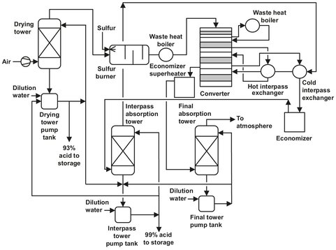
Fig. A.5: Double-absorption process flow sheet. Adapted from [212].
Usually a sulfuric acid plant consists of a single train, regardless of the production capacity. A horizontal brick-lined combustion chamber is applied to burn the liquid sulfur. Air is first filtered and dried before it enters the combustion chamber. The molten sulfur, at a temperature rangingfrom 135—155 °C, is atomized by spray nozzles. These operate at a typical pressure of about 28 bar to achieve a very fine distribution of the sulfur. The self-sustaining ignition temperature of pure sulfur is 260 °C and a source of ignition is not needed if the chamber is preheated to operating temperatures of 400-425 °C. The sulfur dioxide concentration in the off-gas of the combustion chamber can range from 3 to 14 vot%, but most of the plants employ a concentration of about 10—11 vol%. The SO2 produced is led over multiple catalyst beds to achieve an almost complete conversion to SO3. Most of the plants operating now have four beds. The catalyst used is either platinum or vanadium pentoxide, of which the latter is used almost exclusively. The oxide is supported on kieselguhr or zeolite and promoted with potassium sulfate. It is supposed that the oxygen from the surface of the catalyst is transferred to the SO2, after which the surface of the catalyst is reoxidized by the oxygen from the feed.
In the double absorption process, the conversion of SO2 to SO3 takes place in four catalyst beds, with an interstage SO3 absorption after the third bed. This way the SO2 conversion is raised to 99.7 % instead of 98 %. In the interstage absorption, 90-95 % of the total amount of sulfur trioxide produced in the whole process is absorbed. Absorption takes place in a packed absorption tower where the gas is brought in contact with concentrated sulfuric acid (98.5 %). The typical inlet temperature for the acid ranges from 70—80°C resulting in an outlet temperature of 100—125°C depending on the acid circulation rate. The rise in temperature is due to the sensible heat of the process gas and the heat of hydration from SO3. The acid concentration in the recycle to the absorption is maintained at 98.5 % to minimize the total vapor pressure. Thus preventing the formation of H2SO4 mists in the absorption tower. This is done by the addition of process water and product removal from the recycle. After absorption the remaining process gas has to be heated again from approximately 80 °C to 425 °C. Now the gas is led through a single catalyst bed to convert the last SO2 to SO3. This is absorbed in a column equal to the interstage absorber, except that the last column outlet temperature is lower than 105 °C. This is due to the lower amount of gas absorbed.
A.3 Ammonia-based products
A lot of chemicals are made from ammonia, including, caprolactam, acrylonitrile, urea, and melamine, which are also base chemicals. The greater part of the production is used for the production of fibers.
A.3.1 Caprolactam
Caprolactam is mostly used as a raw material for nylon-6, a commonly used polymer. The actual formation of caprolactam is performed in a hydroxylamine/phosphoric acid buffer solution. The solution has to be regenerated by adding hydrogen, which is used in oximation to form cyclohexanon oxime, an intermediate in the production of caprolactam. The oxime rearranges to caprolactam in oleum. Yields of 98 % can be reached by fine-tuning the process. Scheme A.1 presents the overall reaction scheme.
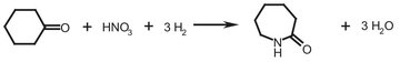
Scheme A.1: Caprolactam formation.
Oxime formation
As illustrated by Fig. A.6 the oximation takes place in a hydroxylamine/phosphoric acid buffer solution. After separation of the oxime, the remaining ammonium phosphate buffer solution is recycled to hydroxylamine synthesis and concentrated. The hydroxylamine formation takes place over a palladium catalyst on a carbon or alumina support by addition of hydrogen. Unreacted hydrogen is separated from the catalyst and recycled. After reaction with the phosphoric acid in the solution, the hydroxylamine phosphate is formed at pH = 1.8.
The hydroxylamine phosphate reacts with the cyclohexanone to form cyclohexanone oxime in the oximation reactor. Water is used as a solvent, and the phosphoric acid is liberated. The oximation reactor consists of a cascade of mixers and separators in a countercurrent system at pH = 2. The extracting agent used is toluene. A conversion of up to 98 % can be achieved. The remaining 2 % of cyclohexanone is oximated with about 3% of the mainstream hydroxylamine phosphate and some added ammonia. The oxime solution (about 30% in toluene) is separated from the water, and the oxime is separated from the toluene. The purified toluene is recycled to the oximation reactorto extract the fresh oxime from the buffer solution. The oxime is fed to the Beckham rearrangement process, which will be discussed later.
To avoid poisoning the palladium catalyst, cyclohexanone and oxime are extracted from the spent buffer solution. This is done using toluene as an extracting agent in a packed column. After removal of this contamination, the toluene is stripped from the buffer solution with steam. The next step before recycling the buffer is the removal of excess ammonium ions. To achieve this, ammonia is burned to NOx in an incinerator. The nitrogen oxide formed is brought in contact with the buffer in the decomposition column, and the nitrogen produced is vented.
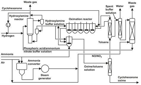
Fig. A.6: Cyclohexanone oxime production flow sheet. Adapted from [213].
Beckham rearrangement process
To obtain caprolactam from the produced oxime, almost all producers use the Beckham rearrangement process. The rearrangement is a very rapid exothermic reaction, and therefore fresh oxime solution in oleum is added to a relatively large amount of already rearranged product. Additional cooling is still needed, which is done by applying a heat exchanger, to keep the temperature at 125 °C. Sometimes sulfur dioxide is added to remove water, which is also formed in the reaction. The sulfuric acid formed catalyzes the reaction and the sulfate of caprolactam is obtained. After neutralization with ammonia a caprolactam solution is formed. In the bisulfate lactam process schematically shown in Fig. A.7, the ammonia consumption is only half that of the conventional processes. The crude caprolactam is removed in a separator drum and extracted with solvents such as benzene or toluene (in conventional processes). In the bisulfate process a commercially available chlorinated hydrocarbon is used, preferably an aliphatic hydrocarbon with one or two carbon atoms. The caprolactam solution is led through an extractor, where the lactam is extracted in a countercurrent process with the chlorinated hydrocarbon. The organic stream is transferred to an atmospheric pressure stripper, and the lactam concentration is increased to about 60 % by evaporating some solvent overhead. The solvent is condensed and recycled. The concentrated lactam solution is again led through an extractor, where this time demineralized water is used as extracting agent. The 30 % aqueous solution contains traces of solvent, which are stripped, condensed, and stored for recycling. The solution is delivered to a conventional caprolactam purification system. This includes two distillation steps to remove any solvent present in the caprolactam. The lactam is obtained in molten form and can be stored as such or be solidified in a flaker.
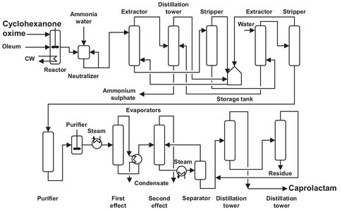
Fig. A.7: Flow sheet of the bisulfate lactam process. Adapted from [212].
The ammonium bisulfate solution from the first extractor and the impure solvent from the second are fed to a distillation column. Pure solvent leaves overhead and the bottom product is an approximately 50 % aqueous solution of ammonium bisulfate. The solvent is stored and recycled, and the waterfrom the aqueous solution is evaporated. The remainder of the solution is incinerated to provide a dilute sulfur dioxide solution. This is further oxidized to trioxide over a vanadium pentoxide catalyst and absorbed in sulfuric acid to produce the oleum used as a solvent in the Beckham rearrangement.
A.3.2 Acrylonitrile
Acrylonitrile is almost exclusively produced by a process designed by Sohio (Standard Oil of Ohio), which basically consists of vapor-phase ammoxidation of propylene over a catalyst. The reaction taking place is given by
![]()
(A.6)
The process itself is simple and conventional in every aspect; no extreme pressures, temperatures, reactors, or materials are needed. Therefore the flow sheet and process description, given in Fig. A.B, appear rather simple.
In a single-pass fluid bed reactor, propylene, ammonia, and air are brought in contact with a catalyst. Modern catalysts are based on a bismuth-molybdenum oxide; formerly iron-antimony, uraniumantimony, and tellurium-molybdenum oxides were used as catalysts. Under normal operating conditions, catalyst regeneration does not have to take place. But when needed, circulating the reactor with air for a short period can do this very easily. The reaction takes place at 400-450 °C and 2 bar with a yield of 75-80 %. Byproducts are HCN, acetonitrile, COX, and nitrogen. The hot reactor effluent is quenched with water in a countercurrent absorber, where any unreacted ammonia is neutralized with sulfuric acid. The absorber off-gas contains N2, CO, CO2, and unreacted hydrocarbons, which can either be vented directly or led through an incinerator before venting. The acrylonitrile solution is led to a recovery column, which produces a crude acrylonitrile (containing HCN) as a top product, and a bottom product, which is led to a second recovery column. In this recovery column a small amount of oxalic acid is used to stabilize the carbonylic cyanohydrins. As a result of this, no volatile contaminants are formed from them, and they leave the column as heavy impurities. The crude acrylonitrile is distilled in a next column, separating the HCN and acrylonitrile. The top product of the second recovery column is a crude acetonitrile, which can either be incinerated or further purified to produce solvent quality acetonitrile.
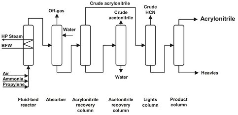
Fig. A.8: Acrylonitrile production. Adapted from [212].
A.3.3 Urea
Urea is used as a raw material for the production of melamine and for fertilizers. Since the introduction of the Stamicarbon CO2-stripping process, more than 100 plants of this type have been built all over the world, indicating the efficiency of this process.
The synthesis stage of the Stamicarbon process (Fig. A.9) comprises a urea reactor, a unconverted reactants stripper, a high-pressure carbamate condenser, and a high-pressure reactor off-gas scrubber. To achieve maximum urea yield per reactor pass at the optimum pressure of 140 bar, an NH3: CO2 molar ratio of 3:1 is used. The major part of the unconverted carbamate is decomposed in the stripper, where ammonia and carbon dioxide are stripped off. This stripping action is accomplished by countercurrent contact between the urea solution and fresh carbon dioxide at synthesis pressure. Low ammonia and carbon dioxide concentrations in the stripped urea solution are obtained, in order to minimize recycling from the low-pressure recirculation stage. These low concentrations of both ammonia and carbon dioxide in the stripper effluent can be obtained at relatively low temperatures of the urea solution, because carbon dioxide is only sparingly soluble under such conditions. Condensation of ammonia and carbon dioxide gases leaving the stripper occurs in the high-pressure carbamate condenser at synthesis pressure. As a result, the heat liberated from ammonium carbamate formation is at a high temperature. This heat is used for the production of 4.5 bar steam for use in the urea plant itself. The condensation in the high-pressure carbamate condenser is incomplete. Remaining gases condense in the reactor and supply the heat required carbamate dehydration, as well as for heating the mixture.
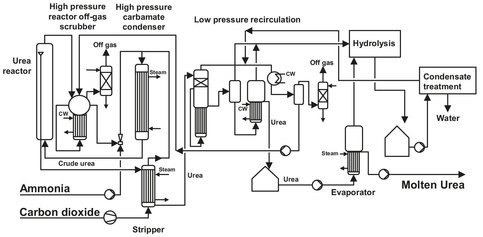
Fig. A.9: Flowsheet of the Stamicarbon CO2-stripping process. Adapted from [213].
In a recent improvement to this process, the condensation of the off-gas from the stripper is carried out in a prereactor, where sufficient residence time for the liquid phase is provided. As a result of urea and water formation in the condensing zone, the condensation temperature is increased, thus enabling the production of steam at a higher pressure. The carbon dioxide feed, originating from an associated ammonia plant, always contains hydrogen. To avoid explosive hydrogen-oxygen mixture formation in the tail gas of the plant, hydrogen is catalytically removed from the carbon dioxide feed. Apart from the air required for this purpose, additional air is supplied to the fresh carbon dioxide input stream. This extra oxygen is needed to maintain a corrosion-resistant layer on the stainless steel in the synthesis section. Before purging the inert gases, mainly oxygen and nitrogen, from the synthesis section, they are washed with carbamate solution from the low-pressure recirculation stage in the high-pressure scrubber to obtain a low ammonia concentration. Further washing of the off-gas is performed in a low-pressure absorber to obtain a practically ammonia free purge gas. Due to the low ammonia and carbon dioxide concentrations in the stripped urea solution, only one low-pressure recirculation stage is required. Because of the ideal ammonia to carbon dioxide ratio in the recovered gases, water dilution of the resulting ammonium carbamate is at a minimum despite the low pressure (about 4 bar). As a result of the stripper efficiency, the quantities of ammonium carbamate for recycle to the synthesis section are also minimized, requiring no separate ammonia recycle. The urea solution from the recirculation stage contains about 75 wt% urea and is concentrated in the evaporation section. When combined with a prilling tower for final product shaping, the urea final moisture content from the evaporation section is ca. 0.25 wt%. If combined with a granulation unit, the final moisture content varies from 1 to 5 wt%, depending on granulation requirements. Higher moisture content can be realized in a single-stage evaporator, whereas a low moisture content is economically achieved by two-stage evaporation. For urea with an extremely low biuret content (max 0.3wt%), pure urea crystals are produced in a crystallization section. These crystals are separated by sieve bends and centrifuges and are melted prior to final shaping in a prilling tower or granulation unit. The process condensate resulting from the evaporation or crystallization sections contains ammonia and urea. Before purging this process condensate, urea is hydrolyzed into ammonia and carbon dioxide, which are stripped off with steam and returned to urea synthesis via the recirculation section. This process condensate treatment section can produce high purity water, thus transforming this “wastewater” treatment into a unit of valuable process condensate production, suitable for boiler feed or cooling tower water makeup.
A.3.4 Melamine
For the low pressure production there are three (commercial) processes available: the BASF, the Chemie Linz, and the Stamicarbon process. Because the Stamicarbon process is the most commonly used, it is discussed here. Scheme A.2 gives the reaction of urea into melamine.
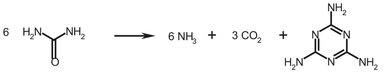
Scheme A.2: Melamine formation from urea.
The DSM Stamicarbon process (Fig. A.10) involves only a single catalytic stage and is operated at 7 bar, with pure ammonia as the fluidizing gas. The catalyst is of the silica alumina type, and melamine is recovered by water quenching and recrystallization from the reactor outlet gas. Urea melt is fed into the lower part of the reactor. The silica alumina catalyst is fluidized by preheated (150 °C) ammonia, entering the reactor at the bottom of the reactor to fluidize the catalyst bed, and at the urea nozzles to atomize the urea feed. The temperature is maintained at 400 °C by circulating molten salt through heating coils in the catalyst bed. The melamine-containing reaction mixture from the reactor is quenched in a quench cooler followed by a scrubber with recycled mother liquor from the crystallization section. The resulting melamine suspension is concentrated to ca. 35 wt% melamine in a hydrocyclone, before feeding it to a desorption column, in which part of the ammonia and carbon dioxide dissolved in the suspension is stripped off and returned to the scrubber. After reducing the pressure the suspension leaving the bottom of the desorber is diluted with a combination of recycled and preheated mother liquor and water. Activated carbon and filter aids may be added to remove color. The melamine dissolves completely, although multiple vessels are necessary to allow sufficient time for dissolution. The resulting solution is filtered and melamine crystallization carried out in a vacuum crystallizer. The crystals are separated from the mother liquor by hydrocyclone and centrifuge, dried in a pneumatic dryer and then conveyed to product bins. Surplus ammonia is recovered as fluidizing gas from the wet ammonia carbon dioxide mixture leaving the desorption column and the scrubber. The hot gas mixture is partly condensed through heat exchange with mother liquor from melamine dissolution. At a pressure of 7 bar the condensate and uncondensed gas are sent to an absorption column. Liquid make-up ammonia is fed to the top of this column to condense the carbon dioxide left in the ammonia gas. The ammonia gas is then compressed and recycled for fluidization and ureaatomization to the reactor.
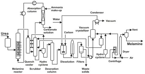
Fig. A.10: Flowsheet of the Stamicarbon melamine process. Adapted from [213].
A.4 Naptha cracking
In this chapter the thermal cracking of naphtha to a number of unsaturated hydrocarbons, such as ethylene, propylene and styrene, is discussed. These are all very important monomers for the production of polymers such as polyethylene and polypropylene. One advantage of the produced aliphatic compounds is that they are more reactive than saturated naphtha. Naphtha is chosen because it is the most used raw material for the production of ethylene and propylene. Ethylene and propylene have lowered the demand for acetylene as an intermediate for polymer production because of the higher production cost of the latter. Steam cracking primarily produces ethylene, but also propylene, and, as secondary products, depending on the feedstock employed, a C4 fraction rich in butadiene and a C5+ fraction with a high content of aromatics, mostly benzene. The variety of products obtained by steam cracking makes this a key process, around which a complex of user installations can be built.
A.4.1 Basic principles
Cracking can be done in several different ways; at high temperatures (750-850 °C, thermal cracking), or at lower temperatures, with the use of a catalyst and by reaction with hydrogen (hydrocracking). The following description concerns a process for thermal cracking. The basic reactions governing the cracking of higher fractions comprise the cracking of a saturated hydrocarbon to a paraffin (containing only single bonds) and an olefin (one double bond). This step is called primary cracking. By secondary cracking, subsequent reactions at various points of their hydrocarbon chain of the species thus formed yield a number of light products rich in olefins, whose composition depends on the feedstock and the operating conditions. An example is shown in Scheme A.3, illustrating the formation of ethylene from heptane through a combination of primary and secondary cracking.
If subjected to subsequent intense dehydrogenation, the compounds thus formed are capable of forming a number of aromatic compounds, particularly benzene. Further dehydrogenation will lead to the formation of coke and tar products, which have a negative impact on the operation of the naphtha cracker. Cracking reactions become significant at temperatures of about 700 °C, whereas dehydrogenation only takes place substantially at temperatures above 800—850 °C. The temperature at which the cracker is operated — higher temperature means higher cracking severity — has a significant influence on the composition of the products, as illustrated in Fig. A.11.
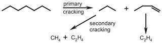
Scheme A.3: Primary and secondary cracking reactions.
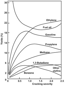
Fig. A.11: Temperature dependence of product composition (vol%).
Because naphtha is a mixture of hydrocarbons, with a boiling point varying from 100-220 °C, and a large variety of products obtained, a naphtha cracker is one of the more complicated crackers. The most important parts are the furnace, in which the actual cracking takes place, and a complex system of fractionation columns, used to separate the product mixture. These two sections are referred to as the hot and cold section. A flow sheet is given in Fig. A.12.
A.4.2 Hot section
The necessary heat for cracking the naphtha is supplied by burning natural gas in several furnaces. The feedstock enters the furnace in the convection zone, where it is preheated and mixed with steam, which is also preheated in this section of the furnace. Here heat transfer takes place by the rising of gases, which is why it is called the convection zone. Next the feedstock is led through the radiation zone of the furnace, where a rapid rise in temperature occurs. The feedstock temperature in this section reaches about 750—800 °C, and the actual cracking takes place. A sketch of a typical furnace is given in Fig. A.13.
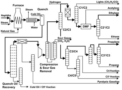
Fig. A.12: Flow sheet of a naphtha cracker.
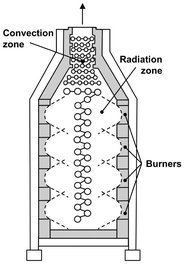
Fig. A.13: Example of a steam-cracking furnace.
The residence time in this zone is shorter than 1s because of the side reactions, such as dehydrogenation, which proceed rapidly at the cracking temperatures. To avoid unwanted side and/or subsequent reactions, the effluents are cooled very rapidly, a so-called quench, and the composition of the mixture is preserved. Quenching generally takes place in two steps: first an indirect quench, using a water-cooled heat exchanger, and a second, direct quench, by adding the heavy pyrolysis byproducts. The heat transfer in the water-cooled heat exchanger is so great that high-pressure steam is generated, which can be used for cracking.
After this the effluents are transferred to a primary fractionating column, where separation takes place between quench oil (C9+ -fraction), a gasoline side stream, and light pyrolysis products. The primary fractionating column operates at a pressure of 1.5 bar and temperatures of 110/170°C (top/bottom). The steam still present in the furnace effluent condenses in the fractionating column and is recycled with make-up process water. The pyrolysis gasoline has a very high percentage of aromatics, mostly benzene, which can be used in several other plants. Styrene production, for example, which will be discussed later, is one of these processes. The light fraction contains a wide range of gaseous products which have to be separated and purified in the cold section. Before entering the cold section, the top product is compressed, resulting in a liquid phase, which is required for distillation.
A.4.3 Cold section
The liquid leaving the compressor still contains some sour gasses, such as CO2 and H2S. For downstream applications it is required to remove these. This can be done by an absorber-stripper combination, using an alkanolamine as solvent for the sour gasses. Because the distillation takes place at high pressure and low temperatures, it is necessary to reduce the water content to about 5 ppm (e.g. drying by molecular sieves) to prevent the formation of ice crystals. This is usually done before the last (of 4-5) compression step.
The first distillation column (33 bar, —40/+95 °C) has a light fraction containing C2 and lower hydrocarbons and a heavy fraction of C3+. The light fraction enters another fractionating column (14 bar, —115/—40 °C), separating the mixture in a CH4/H2/CO mixture (light end) and a heavy fraction containing acetylene, ethylene and ethane. Before distilling the heavy fraction, acetylene is absorbed with di-methyl-formamide (DMF). The last separation step for this end is between ethylene and ethane, which takes place at 8 bar and —60/—30 °C. This a very difficult separation, which is performed in the C2-splitter. This is a distillation column with approximately 120 trays and a relatively high reflux ratio. A C2 splitter can be as high as 90 m, due to the large number of trays needed to separate the ethane from the ethylene. As a result, a high refrigerating capacity is needed in the condenser. The ethylene liquid is drawn from tray 5 (close to the top of the column). Ethane is first used to supply part of the condenser duty in the C2 splitter and then recycled to the furnace to achieve a higher ethylene yield. This leads to a lower energy consumption in two ways: firstly the external cooling in the condenser is reduced, and secondly the heating duty required is lower than without this kind of heat transfer.
The heavy fraction of the first distillation column (C3+ fraction) also undergoes several distillations, first separating C3 and C4 fractions (at 15 bar, 40-100 °C) and then further separation to propylene, propane (from the C3 fraction), a C4, and a C5+ fraction. The most important side products are butadiene, benzene and styrene, which can all be used in several other plants e.g. for polymerization (butadiene and styrene).
A.4.4 Coke formation
One of the most important problems, coke formation, only briefly mentioned in the above discussion, will now be discussed in greater detail. Coke is a term used here for high molecular-weight hydrocarbons with a very low hydrogen content (less than 4 %). These compounds range from tar-like fluids, to fluffy depositions, and even very hard carbon depositions. Despite the precaution taken, coke formation will always occur in this section, mainly at the end of the furnace tube, the inlet of the quench, and the end of the quench, where heavy hydrocarbons from the mixture condense and slowly dehydrogenate. In order to maintain a constant production level, most plants have multiple furnaces, so that one can be cleaned while the others keep production up to the desired level. In practice, cleaning of the furnace has to take place once every two or three months. This can be done by taking the furnace off-line and leading steam with 1 vol% of air through the tubes at an operating temperature ranging from 600-800 °C. This is called slow burning of the coke, which can take up to 30 hours. Addition of extra air can speed up the process: when using 20 vol% of air, for example, the procedure requires only 5 hours. The remaining coke can be mechanically removed by means of high pressure water.
A.5 Oxidation processes
In this chapter three oxidation reactions are described: oxidation of toluene to benzoic acid and phenol, cyclohexane to cyclohexanol and cyclohexanone, and the formation of maleic anhydride from butane. All these processes give more than one product (wanted or unwanted), so again there is a lot of separation technology involved. Oxidation is a type of reaction in which a raw material is reacted with oxygen, which usually is taken from the air. Sometimes, for example in case of equilibrium, the oxygen content of the air is not high enough, and pure oxygen has to be used.
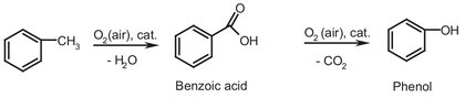
Scheme A.4: Oxidation of toluene to benzoic acid and phenol.
A.5.1 Toluene oxidation
Benzoic acid is an important raw material in the production of caprolactam, which was discussed in Chapter 4. Benzoic acid can also be seen as an intermediate in the production of phenol, as it is the product of the first production step in phenol production shown in Scheme A.4. Between the first and second step, benzoic acid can be (partially) extracted from the process to serve as product or as intermediate for caprolactam production.
The first stage of the production process (Fig. A.14) is the liquid phase oxidation of toluene with atmospheric oxygen over a cobalt catalyst. The second step is the decarboxylation of the isolated benzoic acid, using a copper catalyst. Despite the two-step process, yields of 60-70 mol% can be reached, with a product purity of almost 100 %. The impurities are mostly organic traces, but besides these, the color and color stability, which are considered an indication for the stability and quality of the product, are often important for customers. Various techniques are utilized to improve the color and color stability, but most of them are regarded as trade secrets.
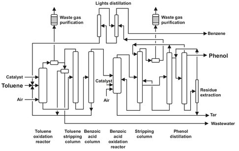
Fig. A.14: Toluene oxidation flow sheet. Adapted from [213].
Fresh toluene is fed into the oxidation reactor together with recycled toluene and the corresponding quantity of catalyst (usually 100—300 ppm). The catalyst used is cobalt naphthenate or benzoate, which are both soluble in toluene. Air is added using air sprinklers. During the reaction, the oxygen content of the air is lowered from 20 to 4 vol%. The waste gas from the reactor, containing toluene and water, is cooled, and toluene absorption takes place on activated carbon. The reactor is operated at 136-160 °C and 1-2 bar, yielding a benzoic acid concentration in the reactor of 40-60 wt%. The reactor is utilized with heat exchangers, because the reaction is highly exothermic. The toluene from the absorber is recycled. The benzoic acid formed is separated from the toluene using a toluenestripping column, and again the toluene is recycled. The bottom product of the column, which consists of benzoic acid and higher boiling byproducts, is distilled again in the benzoic acid column, where the benzoic acid is distilled overhead. The bottom product is disposed or can be led back to the oxidation reactor. One of the byproducts is benzaldehyde, which can be commercially obtained from the mixture by stripping from the reactor effluent.
The purified benzoic acid is led to the decarboxylation reactor, together with 1-5 % of a copper catalyst; this stage also takes place in the liquid phase. The copper is reduced from Cu2+ to Cu+, which is oxidized by the oxygen from the air. To improve the selectivity of the catalyst, metal salts are often added, mainly magnesium salts. The temperature in the reactor is 220-250 °C, and the pressure is only slightly above atmospheric (2.5 atm). Again sprinklers introduce air and water vapor is introduced. The phenol formed is extracted from the reactor as a vapor and separated from inert gasses (which contain some benzene and toluene) in the water-hydrocarbon stripping column. The waste gasses are freed from aromatics and purged. The phenol from the stripping column is distilled in the crude phenol column and for final purification in the phenol column, leaving tar as a bottom product. The bottom product from the stripping column is also tar, but with a high benzoic acid content (high enough to extract and recycle). The benzoic acid is extracted from the tar with water and recycled to the reactor. All the tar streams are combined and incinerated, where complete removal of the catalyst from the flue gas has to be ensured.
A.5.2 Cyclohexane oxidation
Cyclohexane oxidation is used to produce cyclohexanol and cyclohexanone. Until 1940 this was done almost exclusively by hydrogenation of phenol. This process has been completely replaced by the liquid-phase oxidation of cyclohexane. The mixture of cyclohexanol and cyclohexanone is also known as AK oil (from Alkohol-Ketone oil). Unfortunately the formation of adipic acid cannot be prevented, so this becomes a secondary product, which can be extracted from the reactor effluent. Adipic acid is one of the products obtained after oxidation of cyclohexanol. Therefore an optimum in AK-oil yield will be present, as shown in Fig. A.15. Adipic acid is used as a raw material in the production of nylon 4,6. Because the reaction products can be oxidized as easily as cyclohexane, the conversion per passage has to be kept low (about 10 %), to prevent the subsequent oxidation of the desired products. Due to the application of a reflux, the yield is still 70—90 %. If possible the feed should be free of aromatics, because these are resistant to oxidation under the circumstances in the reactor. Therefore they will accumulate as inerts, and a purge has to be installed, resulting in product and raw material losses.
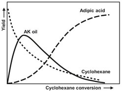
Fig. A.15: AK oil concentration as a function of cyclohexane conversion.
As illustrated in Fig. A.16, oxidation is usually carried out with a soluble cobalt catalyst in a series of stirred autoclaves at 140-180 °C and 8-20 bar. Nowadays, it is even possible to operate the process without a catalyst. Before entering the oxidizers, the feed is preheated, and up to 15 % of water is added to reduce production of cyclohexanol esters. The heat produced in the autoclaves is usually enough to heat the feedstock, so external heat production is not needed. In the stirred autoclaves, air is bubbled through the liquid phase, and part of the water is recycled. The rest of the mixture is led through several oxidizers, and after that through several distillation columns, to remove most of the cyclohexane and part of the added water. The bottom product, which contains AK oil and several byproducts like adipic acid and esters of cyclohexanol, is mixed with sodium hydroxide solution to hydrolyze the formed esters back to cyclohexanol. After drying, the mixture is distilled again, and the cyclohexanone is obtained as the top product. The cyclohexanol is converted by dehydrogenation to cyclohexanone and recycled.
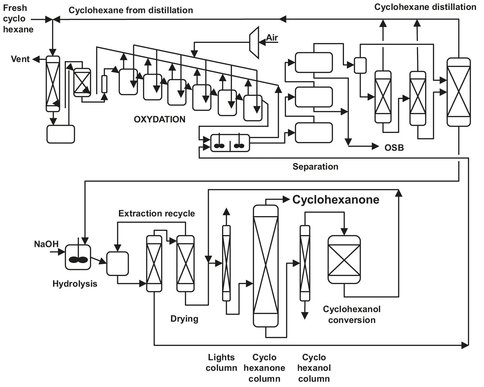
Fig. A.16: Flow sheet of cyclohexane oxidation.
A.5.3 n-butane oxidation
This process was originally carried out in a fixed bed reactor, but since 1989 fluid bed technology has been used in most of the plants. This is called the ALMA process. The basic principle of a fluid bed is a reactor with a finely divided (catalyst) powder, through which a gas is directed. The powder will start moving (in other words, is fluidized) at a certain gas flow and behaves like a fluid. Advantages of this method are the up to 30 % lower investments, the production of high-pressure steam, and very easy temperature control. Due to the homogenous mixing in the reactor, the heat produced by the exothermal reaction (see Scheme A.5) will be equally divided in the reactor, and no hot spots will be formed.
![]()
Scheme A.5: Oxidation of n-butane.
Before the introduction of the ALMA-process, the crude maleic anhydride (MA) was distilled to remove contaminants and byproducts, which required a lot of energy (supplied by steam). The process described uses an organic solvent to recover the MA instead of distillation. MA is used as raw material for unsaturated polyester resin, fumaric and maleic acid and as a lubricant oil additive.
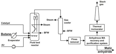
Fig. A.17: n-butane oxidation flow sheet. Adapted from [209].
As can be seen from the flow sheet in Fig. A.17, the butane is first evaporated and then enters the fluid bed reactor. The air is compressed and enters the reactor below the catalyst support to fluidize the catalyst bed. The bed has a temperature of 420-430 °C and a pressure of 3.3 bar. In the conventional process, butane and air were mixed and precautions had to be taken to prevent ignition of this very explosive mixture. Butane content had to be lower than 2 mol% and huge flows where necessary to achieve an acceptable production. The catalyst used is vanadium phosphate (VPO), which is really imported in this process. Normally a catalyst is used to speed up the reaction, but in this case the reaction would hardly take place without the catalyst. The catalyst can be easily replaced, either partially or totally, or the amount can be decreased or increased to meet the desired production capacity (within certain limits of course). Separation of the catalyst from the gas flow takes place partly in the reactor. The last catalyst particles are removed in two cyclones after the gases leave the fluidize bed. Because the reaction taking place is exothermic, heat has to be removed to prevent a rise in temperature. Heat is removed by a cooling system consisting of tubes in the reactor, through which water is led. This way high-pressure steam can be produced. The air and butane are supplied in stoichiometric concentrations, which has the following advantages compared to the fixed bed technology:
· — reduction of the compressor investment and utility due to the smaller volume;
· — smaller reactor size;
· — reduced diameter of the MA absorber.
MA is not the only product formed: unwanted byproducts are CO, CO2, acetic acid, fumaric acid, and acrylic acid. The total yield of MA is only 40—50 %, with a product purity of 98.5 %. A second improvement is the use of an MA recovery system using an organic solvent instead of water. This lowers the steam consumption significantly, because water evaporation does not have to take place, and MA separation can be done in one (absorption) step. The absorption takes place in an absorber-stripper system, using a patented solvent. In the absorber a reaction takes place between the solvent and the MA, which is called reactive absorption. Because the formed bond is very weak, the MA can be easily recovered from the solvent. Molten MA (55—56 °C) can be stored for weeks in stainless steel tanks under an inert gas atmosphere without any change in quality.
A.6 Fischer—Tropsch
In coal and natural gas liquefaction technology, coal or natural gas are converted into a liquid product containing hydrocarbons and oxygenates. The commercially used technologies involves three main process steps:
· (1) synthesis gas production and purification;
· (2) Fischer—Tropsch synthesis;
· (3) product upgrading.
These three steps are schematically represented in the block diagram of Fig. A.18 and will be the subject of further discussion in the following sections. For synthesis gas production the focus is on coal gasification, although the conversion of natural gas by steam reforming (see Section A1.3) is also widely used.
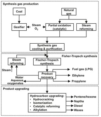
Fig. A.18: Overall process scheme Fischer—Tropsch. Adapted from [208].
A.6.1 Synthesis gas production
A.6.1.1 Coal gasification
The process starts in the gasification plant where coal is converted into crude synthesis gas under pressure and at a high temperature in the presence of steam:
![]()
(A.7)
As example Lurgy dry ash gasifiers can be used, which cope well with the 20 to 40 % ash containing low-grade coal. The normal operating pressure of the Lurgi gasifiers is 27 atm. The gasifier is a countercurrent operation with hot ash exchanging heat with the gasification agent at the bottom and the hot product gases heating, devolatizing and drying the coal fed in at the top (Fig. A.19).
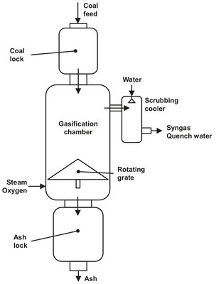
Fig. A.19: Lurgi dry-ash gasifier. Adapted from [208].
A.6.1.2 Gas purification
The gasifier effluent gas contains impurities which interfere with synthesis, and is is first cooled to condense out tars, oils, and excess steam. The lighter oil is hydrofined and added to the gasoline pool.
The rawsynthesis gas is further purified in the Rectisol process. The gas is washed in stages with methanol down to —55 °C to remove most of the CO2 and H2S. The composition of the purified gas is about 13 % CH4, 1% (Ar+N2), 1% CO2, and 85 % (H2 +CO). The total sulfur level of the gas is typically about ![]() . In addition to decreasing the sulfur to the low levels required, the Rectisol process also removes the remaining contaminants such as tar naphtha vapor, ammonia and cyanide.
. In addition to decreasing the sulfur to the low levels required, the Rectisol process also removes the remaining contaminants such as tar naphtha vapor, ammonia and cyanide.
The phenols and cresols dissolved in the steam condensate are recovered by countercurrent solvent extraction (butyl acetate or diisopropyl ether) at the Phenolsolvan plant, and the NH3 is then steam stripped from the water. The phenols are refined and sold, and the NH3 is converted to fertilizer. The remaining water is biologically treated and reused at the complex.
A.6.2 Fischer—Tropsch synthesis
A.6.2.1 Principles
After purification, the clean syngas is catalytically converted to a wide range of products, such as hydrocarbons, alcohols, aldehydes, ketones, and acids. Production of hydrocarbons and alcohols by the Fischer—Tropsch synthesis can be represented as follows:
![]()
(A.8)
![]()
(A.9)
![]()
(A.10)
Reaction (A.8) represents the formation of olefins, reaction (A.9) paraffins and reaction (A.10) alcohols. The proper selection of catalyst and reaction conditions, hydrocarbons and oxygenates ranging from methane and methanol through high (>10 000) molecular weight paraffin waxes can be synthesized. To date iron catalysts are most frequently used in commercial reactors. Not only are they much cheaper to manufacture than their cobalt and ruthenium equivalents, but the products are also more olefinic.
A.6.2.2 Classical reactors
Classically two types of reactors were used. The fixed-bed Arge reactors (Fig. A.20) produce mainly heavy liquid hydrocarbons and waxes, and the transported fluidized-bed reactors (Fig. A.21) make predominantly gaseous hydrocarbons and gasoline. The circulating fluid-bed reactors are known as Sasol Synthol reactors. They have a much higher gas throughput than the fixed-bed reactors. The throughputs of the individual reactors were increased about threefold by increasing the reactor diameters, as well as by raising the operating pressure.
Low temperature fixed-bed reactors (Arge)
A flow sheet representing one fixed-bed reactor train is given in Fig. A.20. The synthesis gas enters at the top of the reactor where it is preheated and then flows through the reactor tubes, which are surrounded by water. By controlling the steam pressure above the water the desired reactor temperature is maintained. The normal operating pressure is 27 atm, and the temperature can vary from 220 to 250 °C. The Fischer—Tropsch reaction is highly exothermic, and to ensure a high rate of heat exchange between the catalyst particles and the tube walls a high linear gas velocity is essential. To obtain a high degree of conversion as well as a high linear gas velocity, part of the tail gas is recycled. A large fraction of the hydrocarbon product is in the liquid phase inside the reactor.
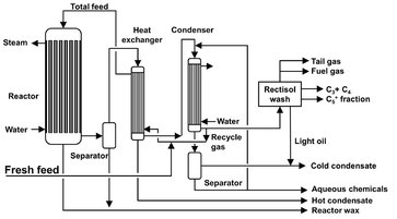
Fig. A.20: Flow sheet of an ARGE fixed-bed reactor. Adapted from [212].
High-temperature Synthol reactors
The Synthol reactors can be described as transported or circulating fluidized beds. The overall height of the reactors is 50 m. As depicted in Fig. A.21, the gas (fresh feed plus recycle) is introduced into the bottom of the reactor, where it meets a stream of hot catalyst flowing down the standpipe. This preheats the gas to its ignition temperature. Gas plus catalyst then flow up through the right-handside reaction zones. The two banks of heat exchangers inside the reactor remove a large portion of the reaction heat, the balance being absorbed by the recycle and product gases. The catalyst disengages from the gas in the wider settling hopper and flows down the standpipe to continue the cycle. The unreacted gas, together with the hydrocarbon product vapors, leaves the reactor via cyclones, which remove the entrained finer catalyst particles and return them to the hopper. The reactor exit temperature is typically around 340 °C. An important operational constraint of the process is that heavy waxy hydrocarbons are detrimental, because they condense on the fine catalyst particles and cause bed defluidization.
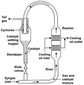
Fig. A.21: Synthol reactor. Adapted from [212].
A.6.2.3 Advanced reactor designs
Slurry-phase reactors
In the slurry-phase reactor the finely divided catalyst is suspended in a heavy oil (Fig. A.22). The liquid medium is usually a Fischer—Tropsch wax with low viscosity at the reaction temperature. The preheated synthesis gas is fed to the bottom of the reactor, where it is distributed into the slurry, and bubbles upward through the slurry. As the gas bubbles upward through the slurry it diffuses into the slurry and is converted into more wax by the Fischer—Tropsch reaction. The liquid medium surrounding the catalyst greatly improves heat transfer and avoids overheating. The heat generated from this reaction is removed through the reactor’s cooling coils, which generate steam and allow high conversions to be reached. Conversion of synthesis gas in a single pass can be as high as 90 %, with a high selectivity for liquids in the gasoline boiling range. The wax product is separated from the slurry containing the catalyst particles in a specially developed process. The lighter more volatile fractions leave in a gas stream from the top of the reactor, which is cooled to recover the lighter cuts and water.
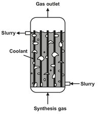
Fig. A.22: Slurry-phase distillate reactor.
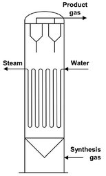
Fig. A.23: Fixed fluidized-bed reactor.
Advanced Synthol reactor
In this fixed fluidized-bed (FFB) reactor the gas passes upward through the catalyst bed at velocities in the region of 10 to 60 cm/s. The catalyst bed, though expanded, is not transported and remains in a fixed position (Fig. A.23). Such a bed is simpler to operate than the circulating bed and, being much smaller, is less costly. The percentage of conversion was found to be independent of the pressure. The fresh feed and recycle flows always increase in proportion to the increase in pressure. Thus FFB reactors have a potential for increased synthesis gas throughputs.
A.6.2.4 Product selectivities
The ARGE fixed-bed reactor operates at relatively low temperature and is intended to produce a large quantity of wax and a minimum of methane. The objective of the Synthol reactor, on the other hand, is to maximize production of materials in the boiling range of gasoline. Hydrocarbons from the Synthol reactors are substantially more olefinic than those produced in the ARGE system, and the fluid-bed reactors produced considerably more oxygenated species, with ethanol being the primary product.
B Polymer Manufacturing
B.1 Polyethylene
B.1.1 High-pressure process
The high-pressure process is used to manufacture almost 20 % of the worldwide polyethylene (PE) production. It was the first commercially available process. The first plant (owned by ICI) began operation in 1939 and produced LDPE (low density polyethylene) at 2000 bar, which was used in cables and other devices for radar because of its excellent insulation properties at high frequencies. High pressure LDPE has an important advantage concerning today’s emphasis on the environment and recycling of plastics: it is catalyst free. Incineration for energy recovery is one approach to plastics recycling, and incinerating high-pressure LDPE does not release metal catalyst particles into the atmosphere. Because of this there has been an upswing in interest for LDPE with the market still growing. The largest single-train high-pressure plant ever built has a production capacity of 185 kt/y and offers considerable economy of scale. For a flow sheet of this plant see Fig. B.1.
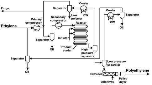
Fig. B.1: Flow sheet of a high-pressure polyethylene plant. Adapted from [212].
Ethylene feedstock is compressed to 250 bar by a primary compressor and then to between 2000 and 2500 bar by a secondary compressor. It is preheated to an initiation temperature of 14 °C and enters the reactor in a plug flow regime where polymerization is started by adding peroxide initiator. The reaction being exothermic, the temperature rises until all initiator is consumed. Temperature peaks of up to 350 °C have been recorded. This way conversion rates up to 37 % can be obtained, depending on product grade and required quality. Reactor tubes are cooled, using a jacket filled with high-pressure water at 200 °C. When the temperature has dropped sufficiently, fresh initiator is added. The tubular reactor can be as long as 0.5 to 1.5 km, usually divided into a number of straight sections connected by 180° curves. The inside diameter of the tubes can range from 25-75 mm, and due to the high pressure applied a ratio of outside-to-inside diameter of about 2.5 is needed to provide the necessary strength. When polymerization is complete, the LDPE and unconverted ethylene are expanded to around 250 bar through a product cooler into a high-pressure separator, from which the ethylene can be recovered, cooled, and recycled to the suction side of the secondary compressor. The remaining ethylene dissolved in the LDPE is recovered in a low-pressure separator, which also serves as hopper for the homogenizing extruder. The extruder has one or more degassing sections for further devolatilization of the LDPE melt.
LDPE pellets from this process can be produced with densities from 919 to 928 kg/m3. This reactor design offers benefits in product quality, running costs and safety. Because of its high and stable heat transfer coefficient the reactor can be smaller than in other tubular processes.
B.1.2 Solution polymerization
The process described was designed by Stamicarbon and is called the “compact” polyethylene solution process, because there are fewer steps involved than in conventional systems. It was originally designed to produce HDPE (high-density polyethylene), but after a few small modifications it can be used for LLDPE (linear low-density-polyethylene) and every other density PE. Fig. B.2 gives a flow sheet of the process described below.
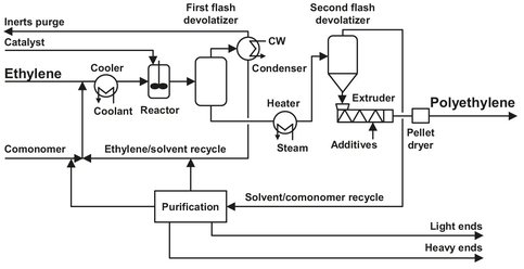
Fig. B.2: Flow sheet of the Stamicarbon polyethylene solution process. Adapted from [211].
First of all, the (polymer grade) ethylene is absorbed by an (inert) solvent under the removal of absorption heat. Hexane, for example, can be used as a solvent, which is recycled from the first flash vessel. The catalyst, diluted in the solvent, is added to an agitated vessel-type reactor, together with the ethylene solution. Reactor feed is cooled to maintain a constant temperature of 150-250 °C in the reactor, depending on the desired product. The pressure in the reactor is between 50 and 100 bar. The conversion per pass is relatively high, compared to the other processes. Mixing requirements for the reactor are severe, because of the short residence time (< 10 min.), small amount of catalyst, and high conversion. The catalyst is composed of several commercially available, but proprietary components.
The heat of the reaction is used to flash almost all of the unreacted ethylene and most of the solvent. The overhead is condensed and recycled to the reactor. By controlling the flash, the solution concentration in the reactor vessel can be adjusted. Only a small purge is needed to prevent inert buildup. The polymer obtained is very pure, but the remaining catalyst is still deactivated by a catalyst deactivator. In order to reduce the content of volatiles, the solution is heated and subsequently flashed. The required additives are added to the molten polymer before pelletizing and solidifying in water. The pellets are dried in a so-called “pneumatic impact drier”, which has the advantage that, apart from the air blower, no rotating parts are present, and energy and maintenance costs are low.
The solvent from the second flash vessel has to be purified before recycling. This is done using a combination of distillation, extraction, and drying steps. These are used to remove light ends, heavy ends, and water, respectively. As an extra precaution, the solvent is led over molecular sieves to remove even more water.
B.1.3 Slurry process
This process is capable of producing the whole range of HDPE resins, from low molecular weight waxes to resins with high molecular weights. Even the production of UHMWPE (ultrahigh molecular weight PE) is possible. This type of PE production can be subdivided into four different types. Two of them employ loop reactors with a diluent circulating at high speed: one using a low boiling hydrocarbon as solvent, and the other a high boiling one. The third type uses a continuously stirred tank reactor with a high boiling solvent, and the last is a liquid pool process, which uses propane or butane as a solvent.
The Phillips Petroleum Company designed the process described in 1961 (see Fig. B.3). Because it is one of the most efficient, a major part of all the HDPE is produced by this process. It produces PE ranging in density from 920 to 970 kg/m3 and ranging from very high to very low molecular weight. The process uses two types of catalysts. The first is a chromium catalyst which has to be activated by fluidization in hot air. Activating conditions are important, because, to some extent, they determine the properties of the PE. The melt index as well as the molecular weight distribution can be varied from medium to broad. The second catalyst is organometallic, producing a narrow molecular weight distribution. The feedstock is ethylene, to which a number of comonomers can be added, such as 1-hexene. The hydrocarbon carrier is isobutane. Hydrogen is used for molecular weight control. The reactor is operated at temperatures of 95-110 °C and pressures of 30-45 bar. The reactor either takes the form of a pipe loop or a number of loops, with an axial pump to circulate the components. The pipe has vertical sections up to 50 m, connected by horizontal pipes of about 5 m. The pipe diameter is in the range of 0.5—1.0 m. Typical gas velocities are in the range of 5—12 m/s, to ensure a turbulent flow regime. This is done to achieve good heat exchange with the cooling water and to prevent polymer deposition on the walls.
As the polymerization reaction is exothermic, the reactor is jacketed with a cooling water system. Temperature is controlled accurately throughout the reactor: precise temperature control is important for a consistent finished product. A plant will have a number of reactors, each reactor being designed for a specific product. The number of reactors will depend on the operator’s requirements. In the reactor, particles of PE are produced, suspended in the carrier, with a total PE content of up to 40 wt%. The polyethylene is formed in the catalyst pores, and because of the internal pressure the particle pulverizes. This way the catalyst is evenly divided throughout the polymer product. The slurry is allowed to settle in settling legs and a polymer-slurry of about 55 wt% is removed from here. A small amount of diluent is added through the settling legs in countercurrent flow with the falling polymer particles. This is done to remove unreacted ethylene from the product and thereby achieve a higher monomer conversion.
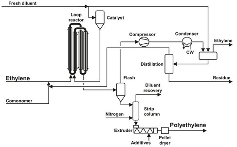
Fig. B.3: The Phillips Petroleum slurry polyethylene process. Adapted from [211].
After leaving the reactor the slurry travels to a flash chamber where the components are separated. Gases and light hydrocarbons volatilize and exit through the top and the PE powder through the bottom. The exitingvapor stream is filtered to remove entrained PE and then passes via a compressor to a fractionation column to recover and recycle isobutane. Vapor from the column passes via an accumulator either to an ethylene plant for ethylene recovery or to a boiler for incineration. Meanwhile the PE powder passes to a purge column, where nitrogen is used to further reduce residual hydrocarbons. The powder then passes to an extruder for incorporation of additives, melt mixing, and pelletizing. Phillips indicated that the process is cheap to build and operate. There is no polymer buildup on the reactor walls, so it is not necessary to schedule shutdowns for reactor cleaning. Waste from the process is low in quantity and limited to a few chemicals; liquid hydrocarbon waste comes from the bottom of the fractionator and can be discharged to a flare or a recovery system. Small emissions of gaseous hydrocarbons are flared.
B.1.4 Gas-phase process
Several patented processes have been designed to produce PE in the gas phase. One of the most efficient is the UNIPOL process, originally developed by Union Carbide in 1968. Its original design was only capable of producing HDPE, but after a few modifications it can now produce LLDPE as well. In addition Union Carbide joined with Shell Chemical Company to use the UNIPOL process with Shell’s highly active SHAC catalyst for polypropylene production. The process is widely used because of its simplicity, cost efficiency, and flexibility.
The UNIPOL process for HDPE or LLDPE is shown in Fig. B.4 and uses a fluidized-bed reactor. Use of the process is growing rapidly because of its simplicity and favorable economics. Its success depends heavily on the development of a highly active and selective catalyst. The first catalyst consisted of chromium compounds and optional modifiers on dehydrated silica. This catalyst is fed as a dry powder to the lower region of the fluidized-bed reactor. The operating pressure (set by economic factors) is ca 20 bar. During reactor operation, this pressure is maintained by controlling the flow of makeup ethylene into the system. The reactor can be rather high (up to 30 m) with a length to diameter ratio of approximately 7. There is however, a larger disengagement zone at the top, where the gas velocity drops, allowing entrained particles to fall back. Solvents have been eliminated, and the recirculating ethylene gas fluidizes and transports the powder, providing heat and mass transfer, and raw material. Because of the rapid recycling of ethylene, which is needed for fluidization and for heat removal, the conversion per pass is only 2 %. Ethylene, heated by the powder, is taken overhead through a solids-disengaging zone in the upper part of the fluid-bed reactor. After pressurizing with a blower, the overhead gas is forced through a cooler designed to minimize deposition of the small amount of entrained reactive fines. Makeup monomer (and comonomer, if LLDPE is desired) is added, and the cooled gas is directed back into the reactor through a gas-distribution nozzle system designed to support the bed, promote turbulence, and allow entrained fines to return to the bed. Reaction temperatures are 70-105 °C; a compromise between achieving high catalyst activity with rising temperature and keeping a safe margin below the softening point of the polymer, which is 125 °C for HDPE or 100 °C for LLDPE. If the gas cooler uses typical cooling-tower water, the available temperature difference for cooling the gas is 40-50 °C. Under these conditions, the heat balance requires that the gas-recirculation rate is 40-50 times larger than the gas makeup or production rate of the reactor. Sensors determine the heat gained by the gas traversing the bed and adjusts the catalyst feed rate to control the production rate.
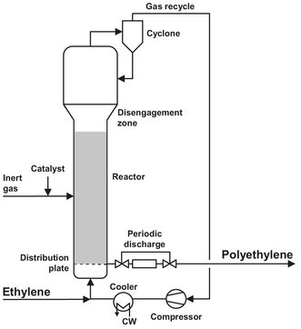
Fig. B.4: Flow sheet of the UNIPOL process. Adapted from [212].
After an average residence time of 3—5 h in the fluid-bed reactor, the powder particles have an average diameter of 500 micrometer. The powder is released intermittently near the bottom of the fluidized bed through specially designed abrasion-resistant valves and is sent with the included gas to a two-stage separation section. This separation section is shown in Fig. B.5. The system uses gravity and the pressure drop across the bed to transfer resin into the upper tank while venting gas back into the top of the reactor. After the upper tank is filled, it is isolated from the reactor, and the resin is discharged into the lower tank. This forces gas in the lower tank from the previous discharge into the upper tank, where it can be recycled to the reactor on the next discharge to the upper tank. With a release to nearly ambient pressure, up to 90 % of the included (and some dissolved) gas is readily separated from the powder, compressed, and returned to the reactor loop without any need for purification. After the powder passes through a gas-lock valve system, nearly all of the regaining monomer is purged from it with nitrogen, and the powder can be air-conveyed to blending, finishing, and storage. The Unipol process eliminates all solvent separation and recovery. In addition, high catalyst activity generates so much polymer per mass of catalyst that hardly any residue remains, i.e., perhaps 1 ppm chromium and neither de-ashing nor deactivation is required. Catalyst selectivity has been improved, and low molecular weight fractions, which can make the powder sticky, are nearly eliminated. Polymer deposits fouling the walls are almost totally absent in the fluid-bed reactor, and the product contains no gels. No extraction step is needed. In the absence of moisture, mild steel is the material of construction, except for powder conveying in finishing and storage, where aluminum is used to avoid iron contamination.
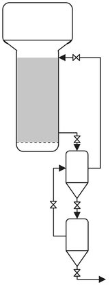
Fig. B.5: UNIPOL product discharge/separation system. Adapted from [211].