5 Steps to a 5: AP Physics 2: Algebra-Based 2024 - Jacobs Greg 2023
STEP 4 Review the Knowledge You Need to Score High
12 Electric Circuits
IN THIS CHAPTER
Summary: Electric charge flowing through a wire is called current. An electrical circuit is built to control the current. In this chapter, you will learn how to predict the effects of current flow. Besides discussing circuits in general, this chapter presents a problem-solving technique: the V-I-R chart, an incredibly effective way to organize a problem that involves circuits.

Key Ideas
![]() The physics concepts of conservation of charge and conservation of energy, as expressed in Kirchhoff’s rules, explain the behavior of circuits.
The physics concepts of conservation of charge and conservation of energy, as expressed in Kirchhoff’s rules, explain the behavior of circuits.
![]() Current is the flow of charge through the circuit.
Current is the flow of charge through the circuit.
![]() A voltage source, such as batteries, generators, and solar cells, supply the energy required to create current.
A voltage source, such as batteries, generators, and solar cells, supply the energy required to create current.
![]() Resistance is a restriction to the flow of current.
Resistance is a restriction to the flow of current.
![]() Resistance depends on the geometry of the resistor.
Resistance depends on the geometry of the resistor.
![]() Not all resistors and circuit elements are ohmic.
Not all resistors and circuit elements are ohmic.
![]() Real batteries are not perfect and have internal resistance.
Real batteries are not perfect and have internal resistance.
![]() The current through series resistors is the same through each, whereas the voltage across series resistors adds to the total voltage.
The current through series resistors is the same through each, whereas the voltage across series resistors adds to the total voltage.
![]() The voltage across parallel resistors is the same across each, whereas the current through parallel resistors adds to the total current.
The voltage across parallel resistors is the same across each, whereas the current through parallel resistors adds to the total current.
![]() The brightness of a lightbulb depends on the power dissipated by the bulb.
The brightness of a lightbulb depends on the power dissipated by the bulb.
![]() A capacitor in a circuit blocks current and stores charge.
A capacitor in a circuit blocks current and stores charge.
![]() Changing the components in a circuit, like opening or closing a switch, has effects on the circuit that can be predicted.
Changing the components in a circuit, like opening or closing a switch, has effects on the circuit that can be predicted.
Relevant Equations
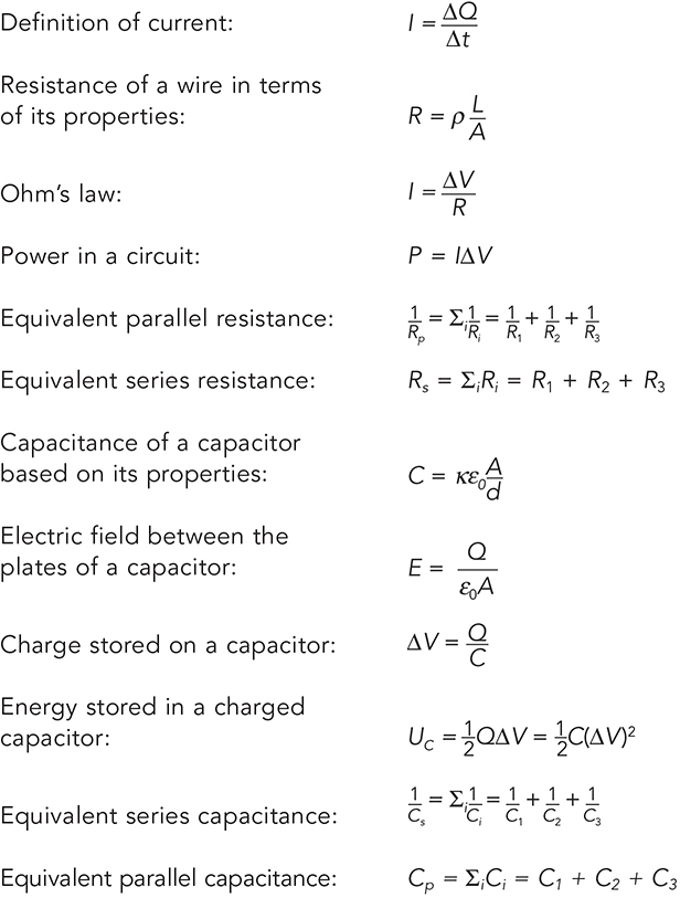
Current
The last chapter talked about situations where electric charges don’t move around very much. Isolated point charges, for example, just sit there creating an electric field. But what happens when you get a lot of charges all moving together? That, at its essence, is what goes on in a circuit.
A circuit is simply any path that will allow charge to flow.
Current: The flow of positive electric charge. In a circuit, the current is the amount of charge passing a given point per unit time.
A current is defined as the flow of positive charge. We don’t think this makes sense, because electrons—and not protons or positrons—are what flow in a circuit. But physicists have their rationale, and no matter how wacky, we won’t argue with it—the AP exam always uses this definition.
In more mathematical terms, current is defined as follows:
![]()
What this means is that the current, I, equals the amount of charge flowing past a certain point divided by the time interval during which you’re making your measurement. This definition tells us that current is measured in coulombs/second. 1 C/s = 1 ampere, abbreviated as 1 A.
Resistance and Ohm’s Law
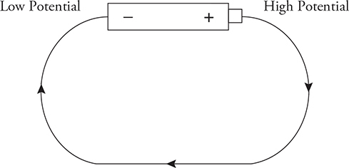
You’ve probably noticed that just about every circuit drawn in your physics book contains a battery. The reason most circuits contain a battery is because batteries create a potential difference between one end of the circuit and the other. In other words, if you connect the terminals of a battery with a wire, the part of the wire attached to the “+” terminal will have a higher electric potential than the part of the wire attached to the “−” terminal. And positive charge flows from high potential to low potential. So, in order to create a current, you need a battery.
In general, the greater the potential difference between the terminals of the battery, the more current flows.
The amount of current that flows in a circuit is also determined by the resistance of the circuit.
Resistance: A property of a circuit that resists the flow of current.
Resistance is measured in ohms. One ohm is abbreviated as 1 Ω.
If we have some length of wire, then the resistance of that wire can be calculated. Three physical properties of the wire affect its resistance:
• The material the wire is made out of: the resistivity, ρ, of a material is an intrinsic property of that material. Good conducting materials, like gold, have low resistivities.1
• The length of the wire, L: the longer the wire, the more resistance it has.
• The cross-sectional area A of the wire: the wider the wire, the less resistance it has.
We put all of these properties together in the equation for resistance of a wire:

Now, this equation is useful only when you need to calculate the resistance of a wire from scratch. Usually, on the AP exam or in the laboratory, you will be using resistors that have a pre-measured resistance.
Resistor: Something you put in a circuit to change the circuit’s resistance.
Resistors are typically ceramic, a material that doesn’t allow current to flow through it very easily. Another common type of resistor is the filament in a light bulb. When current flows into a light bulb, it gets held up in the filament. While it’s hanging out in the filament, it makes the filament extremely hot, and the filament gives off light.
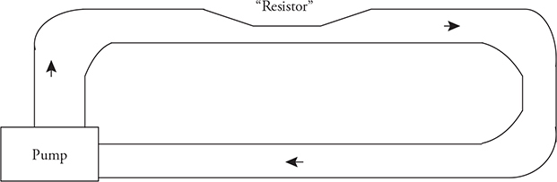
To understand resistance, an analogy is helpful. A circuit is like a network of pipes. The current is like the water that flows through the pipes, and the battery is like the pump that keeps the water flowing. If you wanted to impede the flow, you would add some narrow sections to your network of pipes. These narrow sections are your resistors.
The way that a resistor (or a bunch of resistors) affects the current in a circuit is described by Ohm’s law.
![]()
ΔV is the voltage across the part of the circuit you’re looking at, I is the current flowing through that part of the circuit, and R is the resistance in that part of the circuit. Ohm’s law is the most important equation when it comes to circuits, so make sure you know it well.
When current flows through a resistor, electrical energy is being converted into heat energy. The rate at which this conversion occurs is called the power dissipated by a resistor. This power can be found with the equation
![]()
This equation says that the power, P, dissipated in part of a circuit, equals the current flowing through that part of the circuit multiplied by the voltage across that part of the circuit.
Using Ohm’s law, it can be easily shown that ![]() . It’s only worth memorizing the first form of the equation, but any one of these could be useful.
. It’s only worth memorizing the first form of the equation, but any one of these could be useful.
Ohmic Versus Nonohmic
A circuit component that maintains the same resistance even when the voltage across it, or the current through it, are changed is said to be “ohmic.” Ohmic simply means that the resistance is constant. The exam writers like to ask questions about this. Look at this table of data showing the voltage and current through two resistors. Are the resistors ohmic?

An easy way to check is to rearrange Ohm’s law to solve for resistance and calculate the resistance ![]() .
.
Resistor #1:
First data point: ![]()
Second data point: ![]() . Close . . . let’s check another point.
. Close . . . let’s check another point.
Third data point: ![]() . Stop!
. Stop!
Resistor #1 is nonohmic, because the resistance does not stay constant.
When we repeat the same calculation for Resistor #2, we find that the resistance stays constant at 20 Ω. Resistor #2 is ohmic.
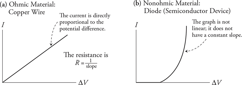
Another quick way to make this ohmic check is to graph the data. In a lab, you could vary the voltage applied to the resistor and measure the current. This would make ΔV the independent variable and I the dependent variable. Rearranging Ohm’s law we would get: ![]() , which means that plotting ΔV on the x-axis and I on the y-axis will result in a slope of 1/R. The slope will be constant (straight line) if the resistor is ohmic. In the above graph (a) is an ohmic material and graph (b) is a nonohmic material.
, which means that plotting ΔV on the x-axis and I on the y-axis will result in a slope of 1/R. The slope will be constant (straight line) if the resistor is ohmic. In the above graph (a) is an ohmic material and graph (b) is a nonohmic material.
Resistors in Series and in Parallel
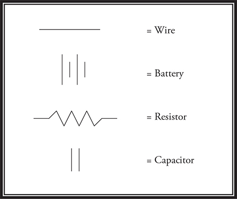
In a circuit, resistors can be arranged either in series with one another or parallel to one another. Before we take a look at each type of arrangement, though, we need first to familiarize ourselves with circuit symbols, shown next.
First, let’s examine resistors in series. In this case, all the resistors are connected in a line, one after the other after the other. In other words, there is only one pathway for the current to travel through.
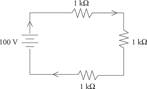
To find the equivalent resistance of series resistors, we just add up all the individual resistors.
![]()
For the circuit in the above figure, Req = 3000 Ω. In other words, using three 1000-Ω resistors in series produces the same total resistance as using one 3000-Ω resistor.
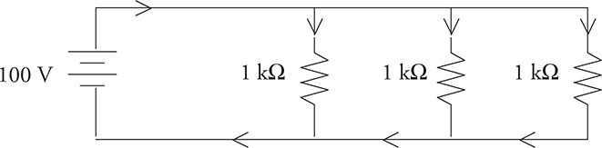
Parallel resistors are connected in such a way that you create several paths through which current can flow. For the resistors to be truly in parallel, the current must split, go through only one resistor in each pathway, and then immediately come back together.
The equivalent resistance of parallel resistors is found by this formula:

For the circuit in the next figure, the equivalent resistance is 333 Ω. So hooking up three 1000-Ω resistors in parallel produces the same total resistance as using one 333-Ω resistor. (Note that the equivalent resistance of parallel resistors is less than any individual resistor in the parallel combination.)
A Couple of Important Rules
Rule #1—When two resistors are connected in SERIES, the amount of current that flows through one resistor equals the amount of current that flows through the other resistor and is equal to the total current through both resistors.
Rule #2—When two resistors are connected in PARALLEL, the voltage across one resistor is the same as the voltage across the other resistor and is equal to the total voltage across both resistors.
The reason why the current is the same for everything connected in a series is because of conservation of charge. Remember that charge is carried by real things, protons and electrons, and they won’t just disappear or be created in a circuit. Since there are no branches in a series pathway, all the charge that enters this single pathway must pass through every component in that pathway.
The reason why voltage is the same for resistors connected in parallel is due to conservation of energy. The voltage (energy per charge) used up in each parallel pathway must be the same. Think of this analogy: water in a river splits along parallel paths to flow around a large island in the middle of the stream. One path may go through rapids with rocks and drop off a waterfall, while the other path around the island may be calm and smooth. Even though the paths are different, the two paths begin and end together at the same height (the same gravitational potential). The same is true for current flowing through parallel paths in a circuit. No matter how different the paths may be, the current must begin and end at the same electric potential. Thus ΔV for parallel paths is always the same.
We will discuss conservation of charge and conservation of energy more a bit later in the section titled Kirchhoff’s Rules. For now, let’s discover a very useful tool: V-I-R charts.
The V-I-R Chart
Here it is—the trick that will make solving circuits a breeze. Use this method on your homework. Use this method on your quizzes and tests. But most of all, use this method on the AP exam. It works.
The easiest way to understand the V-I-R chart is to see it in action, so we’ll go through a problem together, filling in the chart at each step along the way.
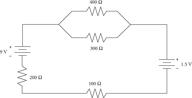
Find the voltage across each resistor in the circuit shown below.
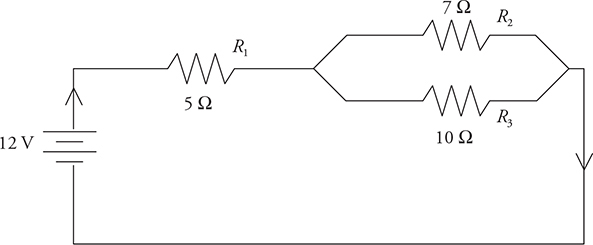
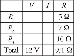
We start by drawing our V-I-R chart, and we fill in the known values. Right now, we know the resistance of each resistor, and we know the total voltage (it’s written next to the battery).
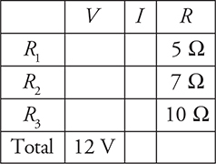
Next, we simplify the circuit. This means that we calculate the equivalent resistance and redraw the circuit accordingly. We’ll first find the equivalent resistance of the parallel part of the circuit:
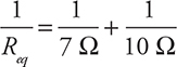
Use your calculator to get 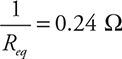 .
.
Taking the reciprocal, we get
![]()
So we can redraw our circuit like this:
Next, we calculate the equivalent resistance of the entire circuit. Following our rule for resistors in series, we have
![]()
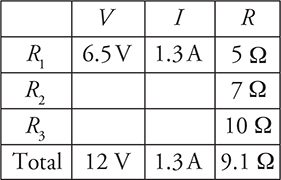
We can now fill this value into the V-I-R chart.
Notice that we now have two of the three values in the “Total” row. Using Ohm’s law, we can calculate the third. That’s the beauty of the V-I-R chart: Ohm’s law is valid whenever two of the three entries in a row are known.
Then we need to put on our thinking caps. We know that all the current that flows through our circuit will also flow through R1. (You may want to take a look back at the original drawing of our circuit to make sure you understand why this is so.) Therefore, the I value in the “R1” row will be the same as the I in the “Total” row. We now have two of the three values in the “R1” row, so we can solve for the third using Ohm’s law.
Finally, we know that the voltage across R2 equals the voltage across R3, because these resistors are connected in parallel. The total voltage across the circuit is 12 V, and the voltage across R1 is 6.5 V. So the voltage that occurs between R1 and the end of the circuit is
![]()
Therefore, the voltage across R2, which is the same as the voltage across R3, is 5.5 V. We can fill this value into our table. Finally, we can use Ohm’s law to calculate I for both R2 and R3. The finished V-I-R chart looks like this:
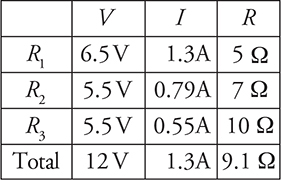
To answer the original question, which asked for the voltage across each resistor, we just read the values straight from the chart.
Now, you might be saying to yourself, “This seems like an awful lot of work to solve a relatively simple problem.” You’re right—it is.
However, there are several advantages to the V-I-R chart. The major advantage is that, by using it, you force yourself to approach every circuit problem exactly the same way.
So when you’re under pressure—as you will be during the AP exam—you’ll have a tried-and-true method to turn to.
Also, if there are a whole bunch of resistors, you’ll find that the V-I-R chart is a great way to organize all your calculations. That way, if you want to check your work, it’ll be very easy to do.
Tips for Solving Circuit Problems Using the V-I-R Chart
• First, enter all the given information into your chart. If resistors haven’t already been given names (like “R1”), you should name them for easy reference.
• Next, simplify the circuit to calculate Req, if possible.
• Once you have two values in a row, you can calculate the third using Ohm’s law. You CANNOT use Ohm’s law unless you have two of the three values in a row.
• Remember that if two resistors are in series, the current through one of them equals the current through the other. And if two resistors are in parallel, the voltage across one equals the voltage across the other.
Kirchhoff’s Rules
Kirchhoff’s rules are expressions of conservation of charge and conservation of energy. They are useful in any circuit but especially in complicated circuits such as circuits with multiple resistors and batteries. Kirchhoff’s rules say:
1. Positive (+) currents entering a junction plus the negative (−) currents leaving a junction equal 0 (ΣIjunction = 0). Or, at any junction the current entering must equal the current leaving.
2. The sum of the voltages around a closed loop is zero (ΣΔVloop = 0).
The first law is called the “junction rule,” and the second is called the “loop rule.” To illustrate the junction rule, we’ll revisit the circuit from our first problem.
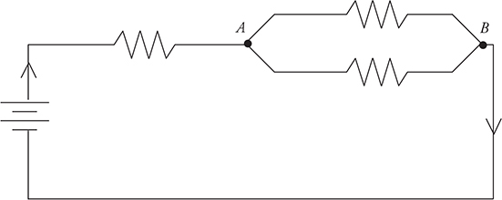
According to the junction rule, whatever current enters junction A must also leave junction A. So let’s say that a current of 1.3 A enters junction A from the left, and then that current gets split between the two branches. If we measured the current in the top branch and the current in the bottom branch, we would find that the two currents still add up to a total of 1.3 A. And, in fact, when the two branches came back together at junction B, we would find that exactly 1.3 A was flowing out through junction B and through the rest of the circuit.
Kirchhoff’s junction rule says that charge is conserved: you don’t lose any current when the wire bends or branches. This seems remarkably obvious, but it’s also remarkably essential to solving circuit problems.
Kirchhoff’s loop rule is a bit less self-evident, but it’s quite useful in sorting out difficult circuits.
As an example, I’ll show you how to use Kirchhoff’s loop rule to find the current through all the resistors in the circuit below.
We will follow the steps for using Kirchhoff’s loop rule:
• Arbitrarily choose a direction of current. Draw arrows on your circuit to indicate this direction.
• Follow the loop in the direction you chose. When you cross a resistor, the voltage is −IR, where R is the resistance, and I is the current flowing through the resistor. This is just an application of Ohm’s law. (If you have to follow a loop against the current, though, the voltage across a resistor is written +IR.)
• When you cross a battery, if you trace from the − to the +, add the voltage of the battery; subtract the battery’s voltage if you trace from + to −.
• Set the sum of your voltages equal to 0. Solve. If the current you calculate is negative, then the direction you chose was wrong—the current actually flows in the direction opposite to your arrows.
In the case of the following figure, we’ll start by collapsing the two parallel resistors into a single equivalent resistor of 170 Ω. You don’t have to do this, but it makes the mathematics much simpler.
Next, we’ll choose a direction of current flow. But which way? In this particular case, you can probably guess that the 9 V battery will dominate the 1.5 V battery, and thus the current will be clockwise. But even if you aren’t sure, just choose a direction and stick with it—if you get a negative current, you chose the wrong direction.
Here is the circuit redrawn with the parallel resistors collapsed and the assumed direction of current shown. Because there’s now only one path for current to flow through, we have labeled that current I.
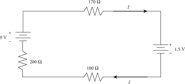
Now let’s trace the circuit, starting at the top-left corner and working clockwise:
• The 170-Ω resistor contributes a term of −(170 Ω) I.
• The 1.5-V battery contributes the term of −1.5 volts.
• The 100-Ω resistor contributes a term of −(100 Ω) I.
• The 200-Ω resistor contributes a term of −(200 Ω) I.
• The 9-V battery contributes the term of +9 volts.
Combine all the individual terms, and set the result equal to zero. The units of each term are volts, but units are left off below for algebraic clarity:
![]()
By solving for I, the current in the circuit is found to be 0.016 A; that is, 16 milliamps, a typical laboratory current.
The problem is not yet completely solved, though—16 milliamps go through the 100-Ω and 200-Ω resistors, but what about the 300-Ω and 400-Ω resistors? We can find that the voltage across the 170-Ω equivalent resistance is (0.016 A)(170 Ω) = 2.7 V. Because the voltage across parallel resistors is the same for each, the current through each is just 2.7 V divided by the resistance of the actual resistor: 2.7 V/300 Ω = 9 mA, and 2.7 V/400 Ω = 7 mA. Problem solved!
Oh, and you might notice that the 9 mA and 7 mA through each of the parallel branches adds to the total of 16 mA—as required by Kirchhoff’s junction rule.
Since the AP exam has a lot of problems without numbers, let’s look at Kirchhoff’s rules symbolically. Look at the circuit in the next diagram. The battery has a voltage of ε; the resistors R1, R2, R3, and R4 are all the same size; and the currents are marked as I1, I2, and I3.
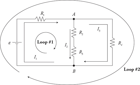
Let’s apply the junction rule to junction A:
![]()
That makes sense. The current into the junction equals the current exiting the junction. We get the same equation for junction B.
Now let’s work with the harder loop rule. We have several loops to choose from, but I’ve already marked loop #1 on the left and loop #2 that goes around the outside. Remember the procedures we have already learned!
![]()
If we rewrite the equation, we can see that the voltage supplied by the battery is completely consumed by the three resistors: ε = I1R1 + I2R2 + I2R3. This is exactly what conservation of energy says we should get. The voltage supplied to the loop is consumed by the components in the loop.
We can also make our math teacher proud and factor out I2: ε = I1R1 + I2(R2 + R3). That tells us that the resistors R2 + R3 add in series, but you already saw that didn’t you?
Now take a look at:
![]()
Solving for ε:
![]()
Compare our two equations:
![]()
They both equal ε, which means we can set them equal to each other:
![]()
Simplifying by canceling out the I1R1 term, we get:
![]()
Remember that ΔV = IR. This equation tells us that the voltage drop across R2 and R3 must equal the voltage drop across R4. But we already knew that because the two combined resistors R2 and R3 are in parallel with R4. That is the parallel rule!
Practice
Now for a good AP exam question:
Using this information and the previous figure:
(A) Rank the currents I1, I2, and I3 from greatest to least.
(B) Rank the voltage drops across the resistors R1, R2, R3, and R4 from greatest to least.
(A) Think about it. I1 has to be the greatest. I2 and I3 split off from I1. But, there is more resistance in the I2 path, so it must be the least.
Answer: I1 > I3 > I2
(B) Remember that all the resistors are the same size. Since ΔV = IR, the voltage drop will depend on the currents. More current = larger ΔV. (Notice that the current through resistors 2 and 3 must be the same because they are in the same pathway.)
Answer: ΔVR1 > ΔVR4 > ΔVR2 = ΔVR3
Get comfortable using Kirchhoff’s rules because it is common for the AP exam to ask you to write them and use them to justify a statement about the circuit.
Circuits from an Experimental Point of View
When a real circuit is set up in the laboratory, it usually consists of more than just resistors—lightbulbs and motors are common devices to hook to a battery, for example. For the purposes of computation, though, we can consider pretty much any electronic device to act like a resistor.
But what if your purpose is not computation? Often on the AP exam, as in the laboratory, you are asked about observational and measurable effects. A common question involves the brightness of lightbulbs and the measurement (not just computation) of current and voltage.
Brightness of a Bulb
The brightness of a bulb depends solely on the power dissipated by the bulb. (Remember, power is given by any of the equations I2R, IΔV, or (ΔV)2/R.) You can remember that from your own experience—when you go to the store to buy a lightbulb, you don’t ask for a “400-ohm” bulb, but for a “100-watt” bulb. And a 100-watt bulb is brighter than a 25-watt bulb. But be careful—a bulb’s power can change depending on the current and voltage it’s hooked up to. Consider this problem.
A lightbulb is rated at 100 W in the United States, where the standard wall outlet voltage is 120 V. If this bulb were plugged in in Europe, where the standard wall outlet voltage is 240 V, which of the following would be true?
(A) The bulb would be one-quarter as bright.
(B) The bulb would be one-half as bright.
(C) The bulb’s brightness would be the same.
(D) The bulb would be twice as bright.
(E) The bulb would be four times as bright.
Your first instinct might be to say that because brightness depends on power, the bulb is exactly as bright. But that’s not right! The power of a bulb can change.
The resistance of a lightbulb is a property of the bulb itself, and so will not change no matter what the bulb is hooked up to.
Since the resistance of the bulb stays the same while the voltage changes, by V2/R, the power goes up, and the bulb will be brighter. How much brighter? Since the voltage in Europe is doubled, and because voltage is squared in the equation, the power is multiplied by 4—choice E.
Ammeters and Voltmeters
Ammeters measure current, and voltmeters measure voltage. This is pretty obvious, because current is measured in amps, voltage in volts. It is not necessarily obvious, though, how to connect these meters into a circuit.
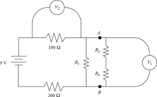
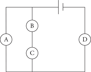
Remind yourself of the properties of series and parallel resistors—voltage is the same for any resistors in parallel with each other. So if you’re going to measure the voltage across a resistor, you must put the voltmeter in parallel with the resistor. In the next figure, the meter labeled V2 measures the voltage across the 100-Ω resistor, while the meter labeled V1 measures the potential difference between points A and B (which is also the voltage across R1).
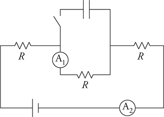
Current is the same for any resistors in series with one another. So, if you’re going to measure the current through a resistor, the ammeter must be in series with that resistor. In the following figure, ammeter A1 measures the current through resistor R1, while ammeter A2 measures the current through resistor R2.
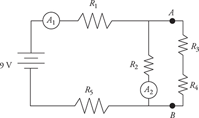
As an exercise, ask yourself, is there a way to figure out the current in the other three resistors based only on the readings in these two ammeters? Answer is in the footnote.2
Real Batteries and Internal Resistance
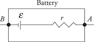
The batteries you use in your calculator or in the lab are not perfect. They have some internal resistance. This means that the voltage posted on the battery, the emf “ε,” is not what actually comes out of the battery, because some of the voltage is lost before it ever gets out! The real voltage supplied by the battery is called the terminal voltage, ΔVterminal. Using the ideas we learned from Kirchhoff’s rules, we can see that:
![]()
where ε is the emf or internal voltage of the battery, I is the current through the battery, and r is the internal resistance of the battery. Notice that more current through the battery means less terminal voltage supplied by the battery to the external circuit.
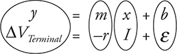
Here is a handy lab that you should know—how to find the internal resistance of a battery. Hook a battery up to a resistor. Using an ammeter and voltmeter, measure the current through the battery and the terminal voltage of the battery. Repeat for several different resistors to produce multiple data points. Plot ΔVterminal as a function of current I and you get a graph that looks like the diagram below.
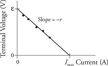
Notice how the graph is linear. When we match up the terminal voltage equations with the equation of a line, we see that the slope equals the negative of the internal resistance r, the y-intercept equals the emf ε of the battery, and the x-intercept will be the maximum current that the battery can output.
Hint: This is one of those labs you might need to know about for the AP exam.
Changes in a Circuit—Switches
A common question on the AP exam is: How does closing a switch affect a circuit? This is an easy question when you know what to do.
• When there is an open switch, the part of the circuit that the switch is in goes dead. Pretend that line and anything in series with this line does not exist. Redraw the circuit eliminating the dead circuit lines so that you don’t get confused.
Let’s take a look at a circuit we used earlier, this time with a switch and let all the resistors be the same: R1 = R2 = R3 = R4 = R.
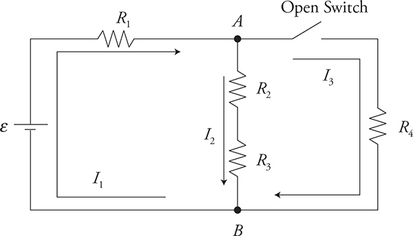
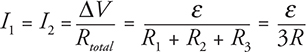
The circuit has an open switch. Therefore, I3 = 0 and resistor R4 receives no current. It is as if it isn’t even there. So, what does that tell us about the circuit? With the switch open, all we have is a simple series circuit with three resistors where I1 = I2:
Now close the switch. What happens to I1 and I2? With the switch closed, we now have a combination circuit with R4 in parallel with R2 and R3. Remember that when resistors are added in parallel, the total resistance of the circuit is lowered. The resistance of the parallel set between points A and B is:
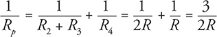
Thus,
![]()
The total resistance of the circuit is:
![]()
To find the total current (I1):
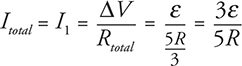
So the current I1 has gone up from ![]() .
.
What about I2? Well, the current I1 will split between I2 and I3, with I2 only getting one-third of the current because it has twice the resistance in its pathway. One-third of ![]() , which is less than the original current of
, which is less than the original current of ![]() before the switch was closed.
before the switch was closed.
If the resistors in this circuit are lightbulbs, this is what happens when the switch is closed:
• Bulb 1 gets brighter.
• Bulbs 2 and 3 get dimmer.
• Bulb 4, which was originally off, comes on and will be brighter than bulbs 2 and 3 but dimmer than bulb 1.
Bottom line: When a switch is open, neglect that portion of the circuit and analyze the circuit as if it isn’t even there.
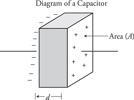
Capacitors
Capacitors were introduced in Chapter 11. Now let’s look at them in more detail. Capacitors are really very simple devices. They have two metal plates, separated from each other by air or a material called a dielectric. A charge builds on the plates, one side positive and the other side negative, and energy is stored in the electric field between the plates. Capacitance is a way to describe how much charge a capacitor can hold for each volt of potential difference you hook it up to. The equation to find the capacitance of a capacitor is:
![]()
where:
• C is the capacitance in farads.
• κ is the dielectric constant of the material between the plates. It has no units.
• ε0 is the vacuum permittivity, the constant we have talked about already.
• A is the area of just one of the plates.
• d is the distance between the plates.
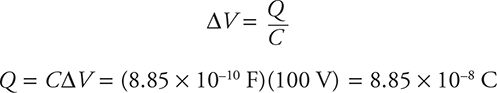
For any capacitor there is a direct relationship between the voltage across the plates and the charged stored on the plates:
![]()
where:
• DV is the potential difference across the plates.
• Q is the charge that is stored on one plate. Be careful, if one plate has positive 2 C of charge on it and the other plate has −2 C of charge on it, the total charge is not 4 C or zero; it is 2 C.
• C is the capacitance of the capacitor in farads.
Example
A capacitor is made of two plates 10 cm by 10 cm separated by 0.1 mm with a 100-V battery across it and a switch. The switch is closed and the capacitor is allowed to charge.
1. Find the charge stored across the capacitor.
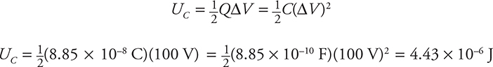
2. Find the energy stored in the capacitor.
3. Find the electric field strength between the plates.
4. The switch is now opened and the distance between the plates is increased to 0.2 mm. What happens to:
(a) the capacitance
(b) the voltage across the plates
(c) the charge on the plates
(d) the energy stored in the capacitor
(e) the electric field strength between the plates
Answers
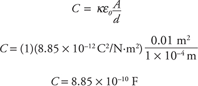
Part 1: First thing we need to do is find the area of the plates. Remember, everything must be in meters, so 0.1 m × 0.1 m = 0.01 m2.
Now let’s find the capacitance. Since again we must be in meters, distance between the plates is 1 × 10—4 m. Air is between the plates, so κ = 1:
To find the charge is now a snap!
Part 2: To find the energy stored, we could use either of these equations from the equation sheet. Both will give the same answer:
Part 3: To find electric field strength:

Now if we had been paying attention, we could have found electric field using ![]() That would have been a lot easier . . . we should pay better attention.
That would have been a lot easier . . . we should pay better attention.
Part 4: Double the distance between the plates and what happens to everything else? This is a classic AP exam question. The first thing to do is decide what is changing and what is staying the same.
Changing: The distance d is doubled. New distance = 2d.
Staying the same: Area of plates A and the charge on the plates Q because the switch was opened and it has nowhere to go. The charge is stuck on the plates. (Note that if the battery has stayed connected to the capacitor, the voltage would stay the same and the charge could change.)
(a) OK, now we have a place to start! Look at the capacitance equation:
![]()
When we double the distance, everything else stays the same, so capacitance is cut in half.
(b) Next, look at the voltage equation for a capacitor:
![]()
With the capacitance cut in half, the potential difference doubles.
(c) We have already decided that the charge stays the same because the switch was open and the charge could not move anywhere.
(d) Energy stored on the capacitor? Take your pick of equations:
![]()
Both equations tell us that the stored energy will double.
(e) OK, this time we are paying attention! Let’s use the easy equation:
![]()
Hey! The electric field stays the same.
This is another one of those skills that the AP exam prizes—semi-quantitative reasoning. Make sure you understand how we worked part 4 of the problem, because it will be a skill that you will use a lot on the exam.
Parallel and Series Capacitors
Lucky for you, you already have a background in parallel and series, which will make your life much easier. Some hints to make solving problems easier:
1. Always draw a circuit diagram and label all the components clearly.
2. Make a chart to keep all your information clear and organized.
3. Keep in mind what is the same in the circuit—I can’t stress enough the importance of this. I’ll explain more as we go through each type of circuit.
Parallel Capacitors
Here is an example of a parallel capacitor circuit.
Remember that some things are the same as resistor circuits and some are different. For a parallel circuit:
• Electric potential difference is the same across each branch of a parallel circuit. This is the same for both capacitor circuits and resistor circuits:
![]()
• The total charge stored across the circuit equals the sum of the charges across each branch of the circuit.
![]()
• The total or equivalent capacitance of a parallel capacitor circuit equals the sum of the capacitance of each branch of the circuit. This is very different from a parallel resistance circuit, in which you add up reciprocals to find the total resistance:
![]()
Example
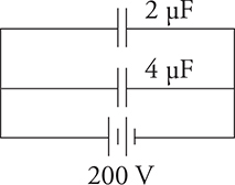
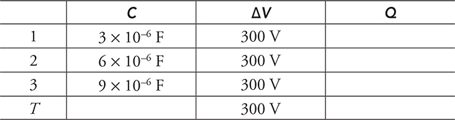
Three capacitors, 3 μF, 6 μF, and 9 μF, are connected in parallel to a 300-V battery. What is the stored charge in the circuit and across each capacitor?
The first thing you want to do is create a C-ΔV-Q chart. Give each capacitor a name like C1, C2, C3, and so on. Give the total or equivalent values a T as shown.

Always ask yourself, “What is the same?” In the case of a parallel circuit, you know there are 300 volts across each leg of the circuit, so fill that into our chart.
There are a couple of ways you can solve from this point. Let’s find the total capacitance of the circuit:
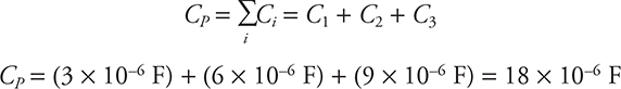
Remember to fill that into your chart under the total capacitance. Now you can find the charge across each capacitor and the total charge using Q = CΔV.
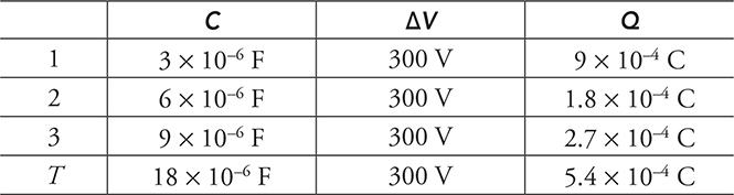
Notice that we could have simply added up the charges across C1, C2, and C3 to find the total charge.
Series Capacitors
Just like in the parallel circuit, some things are the same as resistor circuits and some are different. For a series circuit:
• Electric potential difference adds up in a series circuit. This is the same for both capacitor circuits and resistor circuits:
![]()
• The charge in each series capacitor is the same:
![]()
• The total or equivalent capacitance of a series capacitor circuit equals the sum of the reciprocal of each capacitor in the circuit. This is very different from a series resistance circuit, in which you simply add the resistors to find the total resistance:
Example
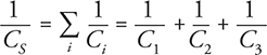
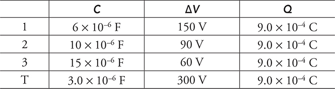
Three capacitors—6 μF, 10 μF, and 15 μF—are connected in series to a 300-V battery. What is the stored charge in the circuit and the electric potential across each capacitor?
Let’s make the chart C-ΔV-Q.
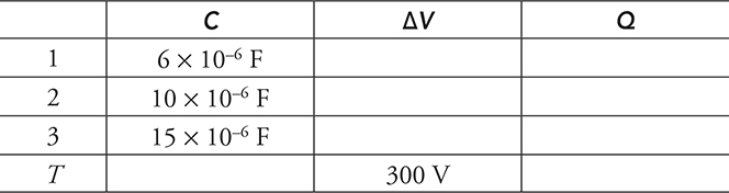
Always ask yourself, “What is the same?” In the case of a series circuit, the charge is constant. In this problem the change is unknown, so the only thing we have enough information to determine is the total capacitance:
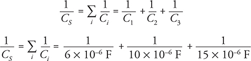
Be careful about your math at this point! Take each reciprocal separately, add them up, and don’t forget to take a reciprocal at the end! You are trying to find CS, not ![]() !
!
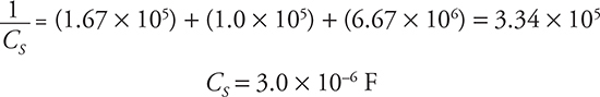
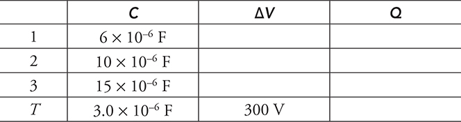
Now you can use Q = CΔV to solve for the total charge, 3.0 × 10—6 F × 300 V = 9.0 × 10—4 C. Remember that charge is the same throughout a series circuit, so you can fill in the entire charge column.
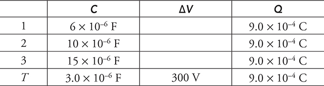
Now use ![]() to find the electric potential across C1, C2, and C3. You know that in a series circuit, the potentials add up to the total, so it is easy to check your answers.
to find the electric potential across C1, C2, and C3. You know that in a series circuit, the potentials add up to the total, so it is easy to check your answers.
Combination Parallel Series Circuits
What if the capacitors are in both parallel and series? Don’t fret; just find the equivalent capacitance using the rules you have already learned.
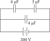
What is the equivalent capacitance of this combination? First, we can see that the top two capacitors are in series. Their equivalent resistance is 2 μF. This 2-μF capacitor is in parallel with the 4-μF capacitor for a grand total of 6 μF. Easy peasy lemon squeezy.
The AP exam probably won’t ask you anything more complicated than that. But what the exam will ask you is how capacitors affect a circuit with resistors in it. So let’s move on to that.
RC Circuits
Sometimes you will be asked to solve a problem with both resistors and capacitors in the circuits. These are called RC circuits. You will only be asked about RC circuits in two different states:
1. When you first connect a capacitor to a circuit, no charge has built up across the plates, so the capacitor freely allows charge to flow. Treat the capacitor like wire with no electrical potential across it.
2. After a long time, steady state will be achieved. The capacitor has built up its maximum charge, and no more current will flow onto the device. The capacitor is “full.” In steady state, the potential difference across the capacitor plates equals the voltage of whatever devices are connected in parallel with it. In steady state, treat the capacitor as an open switch. Every circuit component connected in a series to a capacitor in steady state will receive no current.
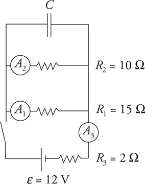
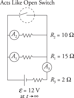
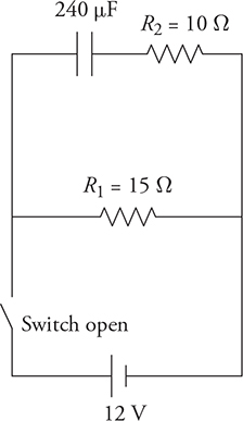
Example 1
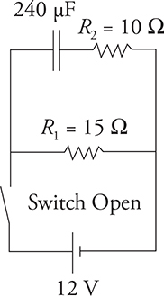
In the circuit in the diagram above, the capacitor is initially uncharged and the switch is opened.
1. Find the currents in the circuit when the switch is first closed.
2. Find the currents in the circuit and the charge on the capacitor after a long time.
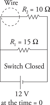
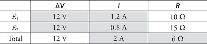
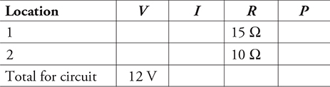
When the switch is first closed, the uncharged capacitor acts like a wire. It is like the capacitor isn’t there, and there is just a parallel circuit as pictured in the diagram above. We can fill in the shaded part of our V-I-R chart just like we did earlier in the chapter.
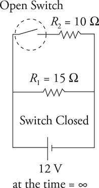
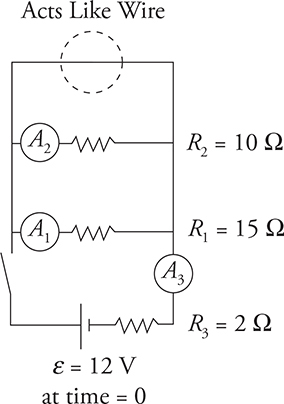
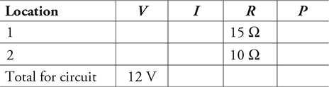
When the switch has been closed for a long time (time approaches infinity), the capacitor becomes charged and it no longer allows current to flow. It becomes like an open switch, as seen in the diagram above. This means the 10-Ω resistor will no longer carry any current and the potential difference across it must be zero. It’s as if the top part of the circuit has been disconnected from the circuit by a switch! Filling in the shaded area of our V-I-R chart, we get:
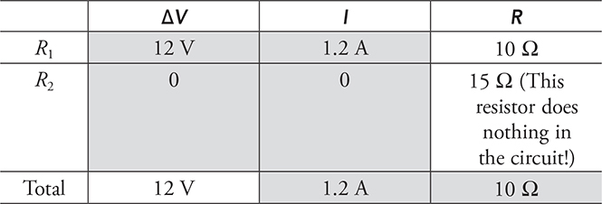
Since the 15-Ω resistor has no current passing through it, the effective circuit is simply a 10-Ω resistor in series with the battery. Therefore, the total resistance of the circuit is just 10 Ω.
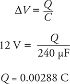
What is the voltage across the capacitor? It is connected in parallel to R1 and the battery. So, 12 volts. The charge on the capacitor would be:
Example 2
In the circuit in the diagram above, we have moved the initially uncharged capacitor to the top in parallel with the resistor R2 and added another resistor R3, and ammeters A1, A2, and A3 to measure the currents.
Here is a great AP exam question: Rank the currents I1, I2, and I3:
(A) immediately after the switch is closed
(B) after the switch has been closed a long time
(A) When the switch is first closed, the uncharged capacitor acts like a wire, and we get the circuit pictured in the diagram above. Notice that the capacitor is acting like a short-circuit wire with no resistance at all. This means all current from the battery will bypass resistors R1 and R2. I1 and I2 will read zero.
Answer: I3 > I1 = I2
(B) After time goes by and the capacitor is full of charge, it acts like an open switch. The circuit is a simple combination circuit. Using what we have learned with Kirchhoff’s rules, we can find the answer.
Answer: I3 > I2 > I1
Note that the capacitor is in parallel with R1 and R2. To find the charge stored on the capacitor, we will need to find the potential difference across R1 and R2.
❯ Practice Problems
Multiple Choice
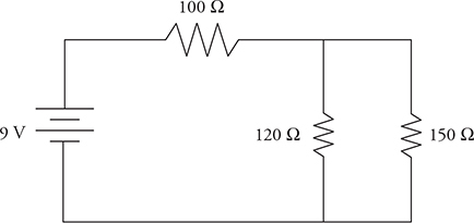
1. 100-Ω, 120-Ω, and 150-Ω resistors are connected to a 9-V battery in the circuit shown above. Which of the three resistors dissipates the most power?
(A) the 100-Ω resistor
(B) the 120-Ω resistor
(C) the 150-Ω resistor
(D) both the 120-Ω and 150-Ω resistors
2. A 1.0-F capacitor is connected to a 12-V power supply for a long time until it is fully charged. The capacitor is then disconnected from the power supply, and used to power a toy car. The average drag force on this car is 2 N. About how far will the car go?
(A) 36 m
(B) 72 m
(C) 144 m
(D) 24 m
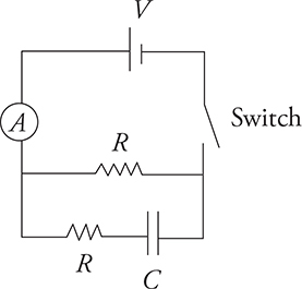
3. The circuit shown in the figure above has two resistors, an uncharged capacitor, a battery, an ammeter, and a switch initially in the open position. After the switch is closed, what will happen to the current measured in the ammeter A?
(A) It will increase to a constant value.
(B) It will remain constant.
(C) It will decrease to a constant value.
(D) It will decrease to zero.
Questions 4 and 5 refer to the following material.
A student is investigating what effect wire diameter D has on a simple circuit. The student has five wires of various diameters made of the same material and length. She connects each wire to a power supply and measures the current I passing through the wire with an ammeter. The data from the investigation is given in the chart.
Output voltage of the power supply: 1.5 V
Length of wires: 1.0 m
Data table:
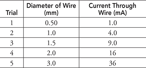
4. What can be concluded from this data?
(A) I ∝ D2
(B) I ∝ D
(C) ![]()
(D) There does not seem to be a relationship between the diameter of the wire and the current.
5. Using the information already gathered, what additional steps would need to be taken to extend this investigation to see if there is a relationship between wire diameter and the resistance of the wire?
(A) Determine what material the wires are made of and look up the resistivity of the wire.
(B) Multiply the current through the wire by the voltage of the power supply.
(C) Divide the current through the wire by the voltage of the power supply.
(D) Divide the voltage of the power supply by the current through the wire.
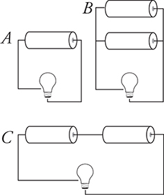
6. Identical lightbulbs are connected to batteries in different arrangements, as shown in the figure above. Which of the following correctly ranks the brightness of the bulbs?
(A) C > B > A
(B) C > B = A
(C) C = B > A
(D) B > C > A
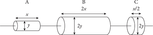
7. Three cylindrical resistors made of the same material but different dimensions are connected, as shown in the figure above. A battery is connected across the resistors to produce current. Which is the correct ranking of the currents for the resistors?
(A) IA = IB = IC
(B) IA > IB > IC
(C) IC > IA = IB
(D) IC > IB > IA
Questions 8 and 9
Two batteries and two resistors are connected in a circuit as shown in the figure below. The currents through R1, R2, and ε2 are shown.
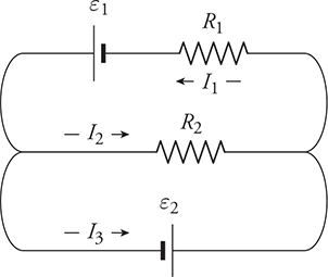
8. Which of the following is a proper application of conservation laws to this circuit? (Select two answers.)
(A) ε1 − I1R1 − I2R2 = 0
(B) ε1 − ε2 − I1R1 = 0
(C) I1 + I2 − I3 = 0
(D) I2 + I3 − I1 = 0
9. The resistors R1 and R2 have the same resistance. If the potential differences of the batteries are ε1 = 9 V and ε2 = 6 V, which resistor will have the most current passing through it?
(A) R1
(B) R2
(C) R1 and R2 have the same current
(D) It is not possible to determine the currents through the resistors without more information
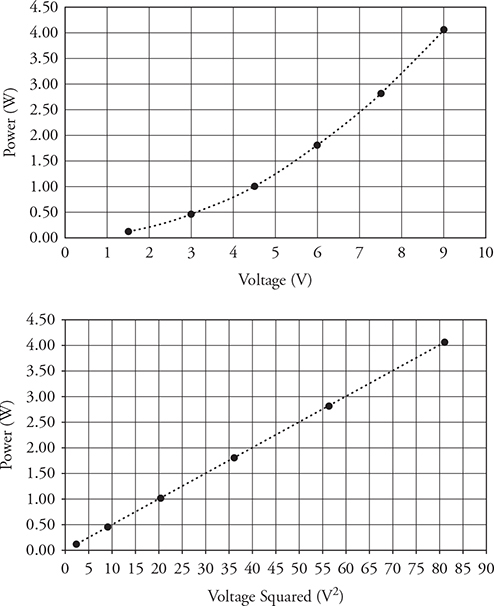
10. A single resistor (R) is connected to a variable voltage source that is increased from 1.5 V to 9 V. The power dissipated by the resistor for various voltages is shown in the two graphs. Which of the following can be deduced from the graphs? (Select two answers.)
(A) The slope of the lower graph can be used to find the resistance (R) of the resistor.
(B) The curve of the upper graph indicates that the voltage source must have internal resistance.
(C) The curve of the upper graph indicates that the resistor is non-ohmic.
(D) The power dissipated by the resistor is proportional to the voltage squared.
Free Response
11.
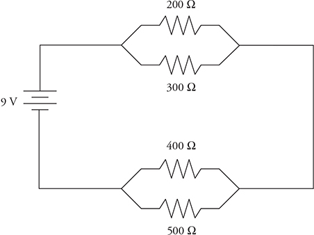
(A) Simplify the above circuit so that it consists of one equivalent resistor and the battery.
(B) What is the total current through this circuit?
(C) Find the voltage across each resistor. Record your answers in the spaces below.
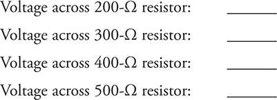
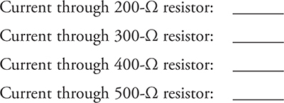
(D) Find the current through each resistor. Record your answers in the spaces below.
(E) The 500-Ω resistor is now removed from the circuit. State whether the current through the 200-Ω resistor would increase, decrease, or remain the same. Justify your answer.
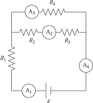
12. A circuit with four identical resistors (R1, R2, R3, and R4), a battery of potential difference (ε), and four ammeters (A1, A2, A3, and A4) is shown in the figure above.
(A) Use Kirchhoff’s junction rule to prove that currents I1 and I4 are the same.
(B) Write Kirchhoff’s loop rule for the loop that contains the battery and resistor R3.
(C) Rank the currents (I1, I2, I3, and I4) from greatest to least. Justify your answer.
(D) Write an expression for the equivalent resistance of the circuit in terms of known quantities.
13. Two lightbulbs have power ratings of 40 W and 100 W when connected to a potential difference of 120 V.
(A) Calculate the resistance of both bulbs. Show your work.
(B) Which bulb glows brightest when connected in parallel? Justify your answer.
(C) Which bulb glows brightest when connected in series? Justify your answer.
14. Four identical bulbs are attached in a circuit, as shown above. Rank the brightness of the bulbs. Justify your prediction in terms of power.
15. Using standard electrical schematic figures, sketch a circuit with bulbs, a battery, a capacitor, and switches that will accomplish the following.
(A) When the switch is closed, the bulb will immediately light but over time will go out.
(B) When the switch is closed, the bulbs will not immediately light, but over time they will glow brighter.
16. The circuit shown in the figure consists of three identical resistors, two ammeters, a battery, a capacitor, and a switch. The capacitor is initially uncharged, and the switch is open. Explain what happens to the readings of the two ammeters from the instant the switch is closed until a long time has passed.
17. The figure shows a circuit with two resistors, a battery, a capacitor, and a switch. Originally, the switch is open, and the capacitor is uncharged.
(A) Complete the voltage-current-resistance-power chart for the circuit immediately after the switch is closed.
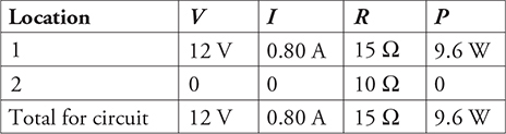
(B) Complete the voltage-current-resistance-power chart for the circuit after the switch is closed for a long time.
(C) What is the energy stored in the capacitor after the switch has been closed a long time?
❯ Solutions to Practice Problems
1. (A) On one hand, you could use a V-I-R chart to calculate the voltage or current for each resistor, then use P = IV, I2R, or ![]() to find power. On the other hand, there’s a quick way to reason through this one. Voltage changes across the 100-Ω resistor, then again across the parallel combination. Because the 100-Ω resistor has a bigger resistance than the parallel combination, the voltage across it is larger as well. Now consider each resistor individually.
to find power. On the other hand, there’s a quick way to reason through this one. Voltage changes across the 100-Ω resistor, then again across the parallel combination. Because the 100-Ω resistor has a bigger resistance than the parallel combination, the voltage across it is larger as well. Now consider each resistor individually.
By power ![]() , the 100-Ω resistor has both the biggest voltage and the smallest resistance, giving it the most power.
, the 100-Ω resistor has both the biggest voltage and the smallest resistance, giving it the most power.
2. (A) The energy stored by a capacitor is ![]() . By powering a car, this electrical energy is converted into mechanical work, equal to the force times the displacement. Solve for displacement, you get 36 m.
. By powering a car, this electrical energy is converted into mechanical work, equal to the force times the displacement. Solve for displacement, you get 36 m.
3. (C) When the switch is initially closed, the uncharged capacitor acts as a “wire” or “closed switch” with no resistance. Thus the initial circuit “looks” like a parallel circuit. As the capacitor charges, the current through the bottom resistor in series with the capacitor drops to zero, as the capacitor acts as a “broken wire” or “open switch” with infinite resistance. Thus, after a long time the circuit becomes a series circuit with current passing only through a single top resistor. As the circuit transitions from this “parallel to series,” the equivalent resistance of the circuit increases. This produces a current through the ammeter that drops from its maximum starting value to a steady-state lower value.
4. (A) As the diameter increases, the current also increases, indicating a direct relationship of some kind. Comparing trials 1 and 2, the diameter doubles and the current quadruples. This suggests a quadratic relationship. To confirm this, compare trials 1 and 3—the diameter is tripled and the current increases by a factor of 9.
5. (D) To investigate the relationship of diameter and resistance, the resistance of the wire needs to be calculated. We already know the output voltage of the power supply and the current through the wire. We just need to calculate the resistance for each entry in the table: ![]() .
.
6. (B) Using Kirchhoff’s loop rule, we can see that the batteries in arrangement C add up to double the voltage. Connecting batteries as in arrangement B does not add any extra voltage to the bulb, and it will not be any brighter than arrangement A.
7. (A) There is only one pathway. The current is the same.
8. (A) and (D) Applying Kirchhoff’s loop rule to the top loop, we get answer choice A. Applying Kirchhoff’s junction rule to the right junction, we get answer choice D.
9. (A) The emfs of both batteries point in the same direction for the outer loop, for a combined potential difference of 15 V. The emfs point in the opposite direction for the line that contains R2, for a combined potential difference of 3 V.
10. (A) and (D) Power (P) equals the Potential Difference (V) squared divided by the Resistance (R). Therefore, the slope of the lower graph in the figure would be equal to 1/R. The Power vs Voltage Squared graph shows power proportional to the voltage squared because the graph is linear. In addition, we can see in the upper graph of the figure that Power as a function of Voltage is quadratic. This also indicates that the Power is proportional to the Voltage squared.
11. (A) Combine each of the sets of parallel resistors first. You get 120 Ω for the first set, 222 Ω for the second set, as shown in the diagram below. These two equivalent resistances add as series resistors to get a total resistance of 342 Ω.
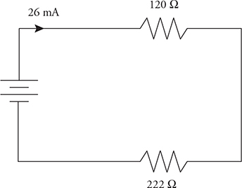
(B) Now that we’ve found the total resistance and we were given the total voltage, just use Ohm’s law to find the total current to be 0.026 A (also known as 26 mA).
(C) and (D) should be solved together using a V-I-R chart. Start by going back one step to when we began to simplify the circuit: 9-V battery, a 120-Ω combination, and a 222-Ω combination, shown above. The 26-mA current flows through each of these . . . so use V = IR to get the voltage of each: 3.1 V and 5.8 V, respectively.
Now go back to the original circuit. We know that voltage is the same across parallel resistors. So both the 200-Ω and 300-Ω resistors have a 3.1-V voltage across them. Use Ohm’s law to find that 16 mA goes through the 200-Ω resistor, and 10 mA through the 300 Ω. Similarly, both the 400-Ω and 500-Ω resistors must have 5.8 V across them. We get 15 mA and 12 mA, respectively.
Checking these answers for reasonability: the total voltage adds to 8.9 V, or close enough to 9.0 V with rounding. The current through each set of parallel resistors adds to just about 26 mA, as we expect.
(E) Start by looking at the circuit as a whole. When we remove the 500-Ω resistor, we actually increase the overall resistance of the circuit because we have made it more difficult for current to flow by removing a parallel path. The total voltage of the circuit is provided by the battery, which provides 9.0 V no matter what it’s hooked up to. So by Ohm’s law, if total voltage stays the same while total resistance increases, total current must decrease from 26 mA.
Okay, now look at the first set of parallel resistors. Their equivalent resistance doesn’t change, yet the total current running through them decreases, as discussed above. Therefore, the voltage across each resistor decreases, and the current through each decreases as well.
12. (A) For the junction on the left: I1 − I2 − I3 = 0. For the junction on the right: I3 + I2 − I4 = 0, therefore, I1 = I4.
(B) ε1 − I1R1 − I2R2 − I2R3 = 0
(C) I1 = I4 > I3 > I2. Currents 1 and 4 are the same and equal to the combination of currents 2 and 3. The currents 2 and 3 have the same potential but different resistances. The resistance is less for current 3; therefore, it is larger than current 2.
(D) 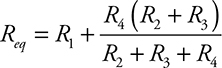
13. (A) 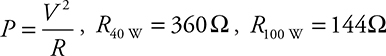
(B)  . When connected in parallel, the bulbs receive the same electric potential, as shown by Kirchhoff’s loop rule. Therefore, the bulb with the smallest resistance (100 W) is brighter.
(C) P = I2R. When connected in series there is only one pathway for the current. The bulbs receive the same current. Therefore, the bulb with the largest resistance (40 W) is brightest.
14. D > A > C = B, P = I2R. All the bulbs have the same resistance. Therefore, the bulb that receives the greatest current will have the greatest power consumption and be brightest. Bulb D is in the main current pathway and receives the greatest current. The main current splits between the two pathways. Bulb A sits in the pathway with the least resistance, so it will receive more current than bulbs C and B. Bulbs C and B are in the same pathway with identical currents and receive the smallest current.
15. There is more than one way to draw each of these, but here is an example.
(A) 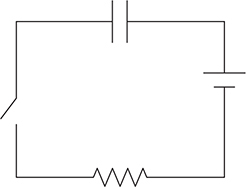
(B) 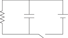
16. When the switch is first closed, the capacitor behaves like a wire. This creates a short circuit around ammeter 1, and it will read zero. All the current is flowing through only two resistors in series and ammeter 2. When the capacitor becomes fully charged, it behaves like an open switch in the circuit. The current is now passing through all three resistors in series. This increases the current in ammeter 1 but decreases the current in ammeter 2 because the total resistance of the circuit has increased.
17. (A)
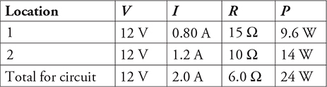
(B) All numbers are rounded to two significant digits.
(C)
❯ Rapid Review
• Current is the flow of positive charge. It is measured in amperes.
• Resistance is a property that impedes the flow of charge. Resistance in a circuit comes from the internal resistance of the wires and from special elements inserted into circuits known as “resistors.”
• Resistance is related to current and voltage by Ohm’s law: ΔV = IR.
• Resistors that have a constant resistance no matter what the current through them or voltage across them are said to be ohmic. If the resistance changes, then these resistors are nonohmic.
• When resistors are connected in series, the total resistance equals the sum of the individual resistances. And the current through one resistor equals the current through any other resistor in series with it.
• When resistors are connected in parallel, the inverse of the total resistance equals the sum of the inverses of the individual resistances. The voltage across one resistor equals the voltage across any other resistor connected parallel to it.
• The V-I-R chart is a convenient way to organize any circuit problem.
• Kirchhoff’s junction rule says that the exact same amount of current coming into a junction will leave the junction. This is a statement of conservation of charge. Kirchhoff’s loop rule says that the sum of the voltages across a closed loop equals zero. This rule is helpful especially when solving problems with circuits that contain more than one battery.
• Ammeters measure current, and are connected in series; voltmeters measure voltage, and are connected in parallel.
• Real batteries have internal resistance that cuts the amount of voltage the battery supplies to the circuit.
• Bulbs are brighter when they are operating at a higher power.
![]()
• When a switch is open, the part of the circuit that is in series with the switch does not receive any current and is “dead.”
• When capacitors are connected in series, the inverse of the total capacitance equals the sum of the inverses of the individual capacitances. When capacitors are connected in parallel, the total capacitance just equals the sum of the individual capacitances.
• A capacitor’s purpose in a circuit is to store charge and energy. After it has been connected to a circuit for a long time, the capacitor becomes fully charged and prevents the flow of current.
• An uncharged capacitor behaves like a wire in a circuit, but once it is charged, it behaves like an open switch.
1Resistivity would be given on the AP exam if you need a value. Nothing here to memorize.
2The current through R5 must be the same as through R1, because both resistors carry whatever current came directly from the battery. The current through R3 and R4 can be determined from Kirchhoff’s junction rule: subtract the current in R2 from the current in R1 and that’s what’s left over for the right-hand branch of the circuit.