AP Physics B Exam
16 Optics
INTRODUCTION
Light (or visible light) makes up only a small part of the entire spectrum of electromagnetic waves, which ranges from radio waves to gamma rays. The waves we studied in the preceding chapter required a material medium for their transmission, but electromagnetic waves can propagate through empty space. Electromagnetic waves consist of time-varying electric and magnetic fields that oscillate perpendicular to each other and to the direction of propagation of the wave. Through vacuum, all electromagnetic waves travel at a fixed speed:
c = 3.00 × 10⁸ m/s
regardless of their frequency. Like all the waves in the previous chapter, we can say v = fλ.
THE ELECTROMAGNETIC SPECTRUM
Electromagnetic waves can be categorized by their frequency (or wavelength); the full range of waves is called the electromagnetic (or EM) spectrum. Types of waves include radiowaves, microwaves, infrared, visible light, ultraviolet, X-rays, and γ-rays (gamma rays) and, although they”ve been delineated in the spectrum below, there”s no universal agreement on all the boundaries, so many of these bands overlap. You should be familiar with the names of the major categories, and, in particular, memorize the order of the colors within the visible spectrum (which, as you can see, accounts for only a tiny sliver of the full EM spectrum). In order of increasing wave frequency, the colors are red, orange, yellow, green, blue, and violet, which is commonly remembered as ROYGBV (“roy-gee-biv”). The wavelengths of the colors in the visible spectrum are usually expressed in nanometers. For example, electromagnetic waves whose wavelengths are between 577 nm and 597 nm are seen as yellow light.
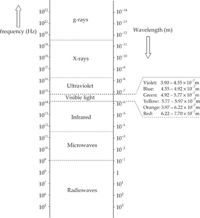
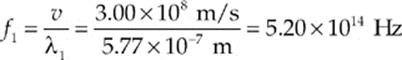
Example 16.1 What”s the frequency range for green light?
Solution. According to the spectrum, light is green if its wavelength is between 4.92 × 10⁻⁷ m and 5.77 × 10⁻⁷ m. Using the equation v = fλ, we find that the upper end of this wavelength range corresponds to a frequency of
while the lower end corresponds to
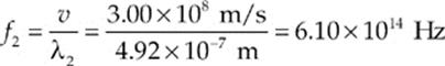
So the frequency range for green light is
![]()
Example 16.2 How would you classify electromagnetic radiation that has a wavelength of 1 cm?
Solution. According to the electromagnetic spectrum presented above, electromagnetic waves with λ = 10–2 m are microwaves.
INTERFERENCE AND DIFFRACTION
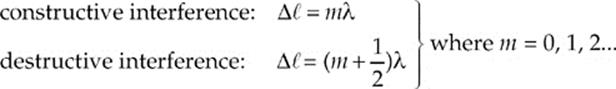
As we learned in the preceding chapter, waves experience interference when they meet, and whether they interfere constructively or destructively depends on their relative phase. If they meet in phase (crest meets crest), they combine constructively, but if they meet out of phase (crest meets trough), they combine destructively. The key to the interference patterns we”ll study in the next section rests on this observation. In particular, if waves that have the same wavelength meet, then the difference in the distances they”ve traveled determine whether the waves are in phase. Assuming that the waves are coherent (which means that their phase difference remains constant over time and does not vary), if the difference in their path lengths, ∆![]() , is a whole number of wavelengths—0, ±λ, ±2λ, etc.—they”ll arrive in phase at the meeting point. On the other hand, if this difference is a whole number plus one-half a wavelength—±
, is a whole number of wavelengths—0, ±λ, ±2λ, etc.—they”ll arrive in phase at the meeting point. On the other hand, if this difference is a whole number plus one-half a wavelength—±![]() λ, ±(1 +
λ, ±(1 + ![]() )λ, ±(2 +
)λ, ±(2 + ![]() )λ, etc.—then they”ll arrive exactly out of phase. That is,
)λ, etc.—then they”ll arrive exactly out of phase. That is,
YOUNG”S DOUBLE-SLIT INTERFERENCE EXPERIMENT
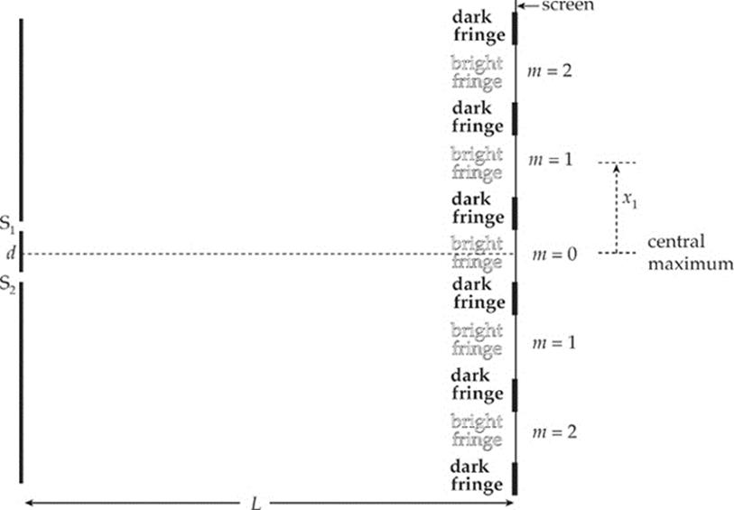
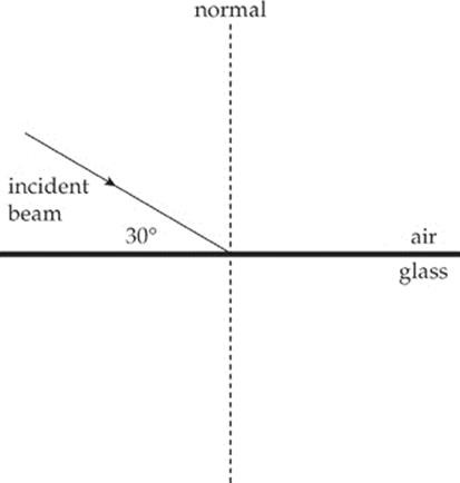
The following figure shows light incident on a barrier that contains two narrow slits (perpendicular to the plane of the page), separated by a distance d. On the right is a screen whose distance from the barrier, L, is much greater than d. The question is, What will we see on the screen? You might expect that we”ll just see two bright narrow strips of light, directly opposite the slits in the barrier. As reasonable as this may sound, it doesn”t take into account the wave nature of light.
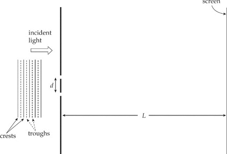
When a wave encounters an aperture whose width is comparable to its wavelength, the wave will fan out after it passes through. The alteration in the straight-line propagation of a wave when it encounters a barrier is called diffraction. In the set-up above, the waves will diffract through the slits, and spread out and interfere as they travel toward the screen.
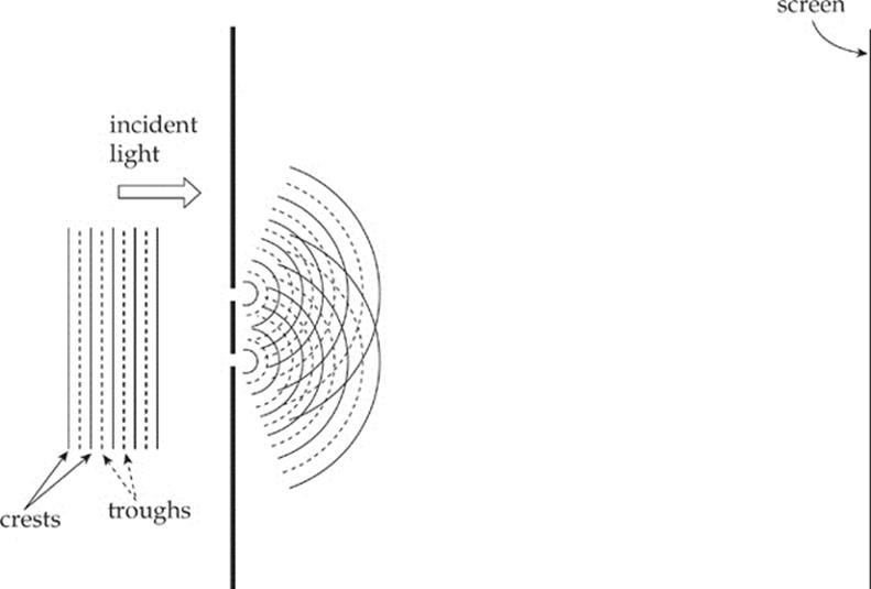
The screen will show the results of this interference: There will be bright bands (bright fringes) centered at those points at which the waves interfere constructively, alternating with dark fringes, where the waves interfere destructively. Let”s determine the locations of these fringes.
In the figure below, we”ve labeled the slits S1 and S2. A Point P on the screen is selected, the path lengths from S1 and S2 to P are called ![]() 1 and
1 and ![]() 2, respectively, and the angle that the line from the midpoint of the slits to P makes with the horizontal is θ. Segment S1Q is perpendicular to line S2P. Because L is so much larger than d, the angle that line S2P makes with the horizontal is also approximately θ, which tells us that ∠S2S1Q is approximately θ and that the path difference, ∆
2, respectively, and the angle that the line from the midpoint of the slits to P makes with the horizontal is θ. Segment S1Q is perpendicular to line S2P. Because L is so much larger than d, the angle that line S2P makes with the horizontal is also approximately θ, which tells us that ∠S2S1Q is approximately θ and that the path difference, ∆ ![]() =
= ![]() 2 –
2 – ![]() 1, is nearly equal to S2Q.
1, is nearly equal to S2Q.
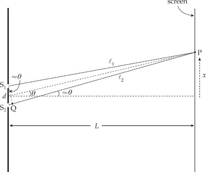
Because S2Q = d sin θ, we get ∆![]() = d sin θ. Now, using what we learned earlier about how constructive or destructive interference depends on ∆
= d sin θ. Now, using what we learned earlier about how constructive or destructive interference depends on ∆![]() , we can write:
, we can write:
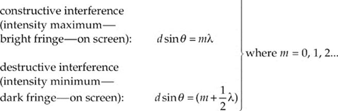
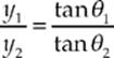
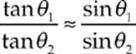
To locate the positions of, say, the bright fringes on the screen, we use the fact that x = L tan θ. If θ is small, then tan θ ≈ sin θ, so we can write x = L sin θ (we can tell this from the figure). Since sin θ = mλ/d for bright fringes, we get

Also, the intensity of the bright fringes decreases as m increases in magnitude. The bright fringe directly opposite the midpoint of the slits—the central maximum—will have the greatest intensity when m = 0. The bright fringes with m = 1 will have a lower intensity, those with m = 2 will be fainter still, and so on. If more than two slits are cut in the barrier, the interference pattern becomes sharper, and the distinction between dark and bright fringes becomes more pronounced. Barriers containing thousands of tiny slits per centimeter—called diffraction gratings—are used precisely for this purpose.
Example 16.3 For the experimental set-up we”ve been studying, assume that d = 1.5 mm, L = 6.0 m, and that the light used has a wavelength of 589 nm.
(a) How far above the center of the screen will the first intensity maximum appear?
(b) How far below the center of the screen is the third dark fringe?
(c) What would happen to the interference pattern if the slits were moved closer together?
Solution.
(a) The central maximum corresponds to m = 0 (x0 = 0). The first maximum above the central one is labeled x1 (since m = 1). The other bright fringes on the screen are labeled accordingly.
The value of x1 is

(b) The first dark fringe occurs when the path difference is 0.5λ, the second dark fringe occurs when the path difference is 1.5λ, and the third dark fringe occurs when the path difference is 2.5λ, so

(c) Since xm = mλL/d, a decrease in d would cause an increase in xm. That is, the fringes would become larger; the interference pattern would be more spread out.
SINGLE-APERTURE DIFFRACTION
A diffraction pattern will also form on the screen if the barrier contains only one slit. The central maximum will be very pronounced, but lower-intensity maxima will also be seen because of interference from waves arriving from different locations within the slit itself. The width of the central maximum will become wider as the width of the slit is decreased.
For a circular pinhole aperture, the diffraction pattern will consist of a central, bright circular disk surrounded by rings of decreasing intensity.
REFLECTION AND REFRACTION
Imagine a beam of light directed toward a smooth transparent surface. When it hits this surface, some of its energy will be reflected off the surface and some will be transmitted into the new medium. We can figure out the directions of the reflected and transmitted beams by calculating the angles that the beams make with the normal to the interface. In the following figure, an incident beam strikes the boundary of another medium; it could be a beam of light in air striking a piece of glass. Notice all angles are measured from the normal.
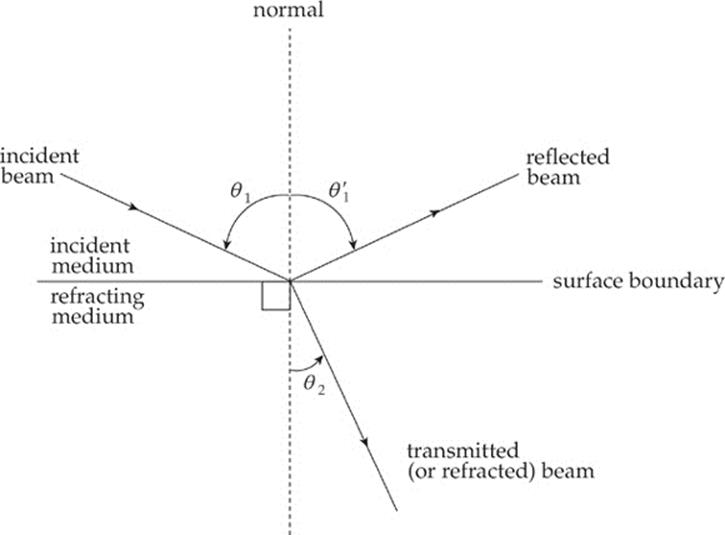
The angle that the incident beam makes with the normal is called the angle of incidence, or θ1. The angle that the reflected beam makes with the normal is called the angle of reflection, θ′1, and the angle that the transmitted beam makes with the normal is called the angle of refraction, θ2. The incident, reflected, and transmitted beams of light all lie in the same plane.
The relationship between θ1 and θ′1 is pretty easy; it is called the Law of Reflection:
θ1 = θ′1
In order to describe how θ1 and θ2 are related, we first need to talk about a medium”s index of refraction.
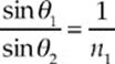
When light travels through empty space (vacuum), its speed is c = 3.00 × 10⁸ m/s; this is one of the fundamental constants of nature. But when light travels through a material medium (such as water or glass), it”s constantly being absorbed and re-emitted by the atoms that compose the material and, as a result, its apparent speed, v, is some fraction of c. The reciprocal of this fraction,
![]()
is called the medium”s index of refraction. For example, since the speed of light in water is v = 2.25 × 10⁸ m/s, the index of refraction of water is
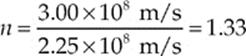
Note that n has no units; it”s also never less than 1.
The equation that relates θ1 and θ2 involves the index of refraction of the incident medium (n1) and the index of refraction of the refracting medium (n2); it”s called Snell”s Law:
n1 sin θ1 = n2 sin θ2
If n2 > n1, then Snell”s Law tells us that θ2 < θ1; that is, the beam will bend (refract) toward the normal as it enters the medium. On the other hand, if n2 < n1, then θ2 > θ1, and the beam will bend away from the normal.
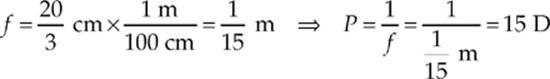
Example 16.4 A beam of light in air is incident upon a piece of glass, striking the surface at an angle of 30°. If the index of refraction of the glass is 1.5, what are the angles of reflection and refraction?
Solution. If the light beam makes an angle of 30° with the surface, then it makes an angle of 60° with the normal; this is the angle of incidence. By the Law of Reflection, then, the angle of reflection is also 60°. We use Snell”s Law to find the angle of refraction. The index of refraction of air is close to 1, so we can say that n = 1 for air.
n1 sin θ1 = n2 sin θ2
(1) sin 60° = 1.5 sin θ2
sin θ2 = 0.5774
θ2 = 35°
Note that θ2 < θ1, as we would expect since the refracting medium (glass) has a greater index than does the incident medium (air).
Example 16.5 A fisherman drops a flashlight into a lake that”s 10 m deep. The flashlight sinks to the bottom where its emerging light beam is directed almost vertically upward toward the surface of the lake, making a small angle (θ1) with the normal. How deep will the flashlight appear to be to the fisherman? (Use the fact that tan θ is almost equal to sin θ if θ is small.)
Solution. Take a look at the figure below.
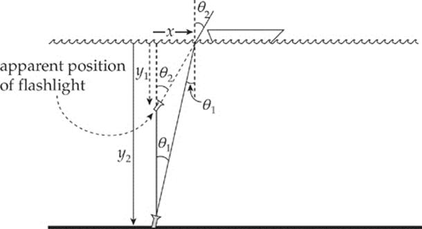
Since the refracting medium (air) has a lower index than the incident medium (water), the beam of light will bend away from the normal as it emerges from the water. As a result, the fisherman will think that the flashlight is at a depth of only y1, rather than its actual depth of y2 = 10 m. By simple trigonometry, we know that
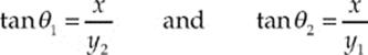
So,
Snell”s Law tells us that n1 sin θ1 = sin θ2 (since n2 = nair = 1), so
Using the approximations sin θ1 ≈ tan θ1 and sin θ2 ≈ tan θ2, we can write
which means

Because y2 = 10 m and n1 = nwater = 1.33,
DISPERSION OF LIGHT
One thing we learned when we studied waves is that wave speed is independent of frequency. For a given medium, different frequencies give rise to different wavelengths, because the equation v = f λ must always be satisfied and v doesn”t vary. But when light travels through a material medium, it displays dispersion, which is a variation in wave speed with frequency (or wavelength). So, the definition of the index of refraction, n = c/v, should be accompanied by a statement of the frequency of the light used to measure v, since different frequencies have different speeds and different indices. A piece of glass may have the following indices for visible light:

Note that as the wavelength decreases, refractive index increases. In general, higher frequency waves have higher indices of refraction. Most lists of refractive index values are tabulated using yellow light of wavelength 589 nm (frequency 5.1 × 10¹⁴ Hz).
Although the variation in the values of the refractive index across the visible spectrum is pretty small, when white light (which is a combination of all the colors of the visible spectrum) hits a glass prism, the beam is split into its component colors.
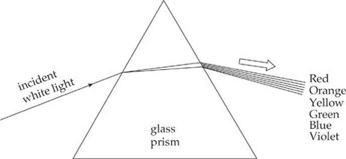
Why? Because each color has its own index, Snell”s Law tells us that each color will have its own angle of refraction. Therefore, each color emerges from the prism at a slightly different angle, so the light disperses into its component colors.
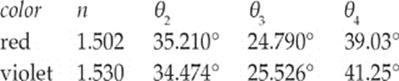
Example 16.6 In the figure above, assume that the incident beam strikes the prism with an angle of incidence of 60.00°. If the top angle of the prism has a measure of 60.00°, what are the angles of refraction of red light and violet light when the beam emerges from the other side? (Use n = 1.502 for red light and 1.530 for violet light.)
Solution. The beam refracts twice, once when it enters the prism and again when it exits.
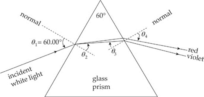
Snell”s Law tells us that
![]()
where n is the index of the glass. We”ll ignore the minuscule variation in n for light in air, and just use nair = 1 for all colors. The relationship between θ2 and θ3 follows from the fact that the sum of the measures of the angles in any triangle is 180°, so
(90° – θ2) + 60° + (90° – θ3) = 180°
which implies that θ3 = 60° – θ2. We can now make the following table of values:
TOTAL INTERNAL REFLECTION
When a beam of light strikes the boundary to a medium that has a lower index of refraction, the beam bends away from the normal. As the angle of incidence increases, the angle of refraction becomes larger. At some point, when the angle of incidence reaches a critical angle, θc, the angle of refraction becomes 90°, which means the refracted beam is directed along the surface.
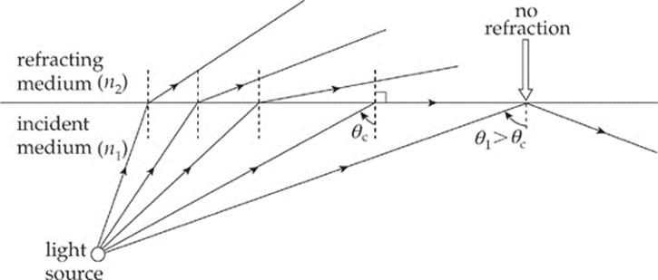
For angles of incidence that are greater than θc, there is no angle of refraction; the entire beam is reflected back into the original medium. This phenomenon is called total internal reflection (sometimes abbreviated TIR).
Total internal reflection occurs when:
1) n1 > n2
and
2) θ1 > θc, where θc = sin–1 (n2/n1)
Notice that total internal reflection cannot occur if n1 < n2. If n1 > n2, then total internal reflection is a possibility; it will occur if the angle of incidence is large enough, that is, if it”s greater than the critical angle, θc.
Example 16.7 What is the critical angle for total internal reflection between air and water? In which of these media must light be incident for total internal reflection to occur?
Solution. First, total internal reflection can only occur when the light is incident in the medium that has the greater refractive index and strikes the boundary to a medium that has a lower index. So, in this case, total internal reflection can occur only when the light source is in the water and the light is incident upon the water/air surface. The critical angle is found as follows:

Total internal reflection will occur if the light from the water strikes the water/air boundary at an angle of incidence greater than 49°.
Example 16.8 How close must the fisherman be to the flashlight in Example 16.5 in order to see the light it emits?
Solution. In order for the fisherman to see the light, the light must be transmitted into the air from the water; that is, it cannot undergo total internal reflection. The figure below shows that, within a circle of radius x, light from the flashlight will emerge from the water. Outside this circle, the angle of incidence is greater than the critical angle, and the light would be reflected back into the water, rendering it undetectable by the fisherman above.
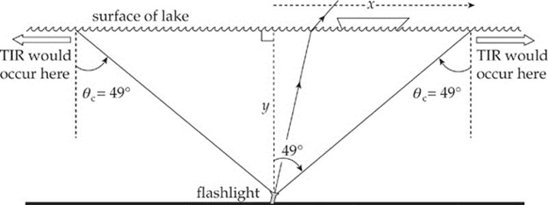
Because the critical angle for total internal reflection at a water/air interface is 49° (as we found in the preceding example), we can solve for x:

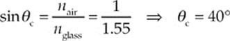
Example 16.9 The refractive index for the glass prism shown below is 1.55. In order for a beam of light to experience total internal reflection at the right-hand face of the prism, the angle θ1 must be smaller than what value?
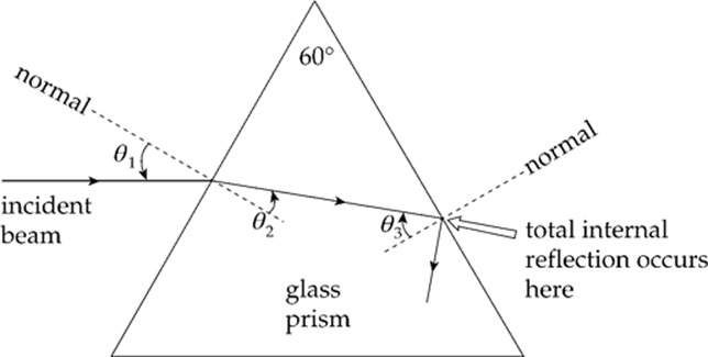
Solution. Total internal reflection will occur at the glass/air boundary if θ3 is greater than the critical angle, θc, which we can calculate this way:
Because θ3 = 60° – θ2, total internal reflection will take place if θ2 is smaller than 20°. Now, by Snell”s Law, θ2 = 20° if
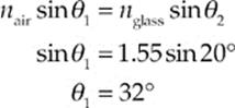
Therefore, total internal reflection will occur at the right-hand face of the prism if θ1 is smaller than 32°.
MIRRORS
A mirror is an optical device that forms an image by reflecting light. We”ve all looked into a mirror and seen images of nearby objects, and the purpose of this section is to analyze these images mathematically. We begin with a plane mirror, which is flat, and is the simplest type of mirror. Then we”ll examine curved mirrors; we”ll have to use geometrical methods or algebraic equations to analyze the patterns of reflection from these.
PLANE MIRRORS
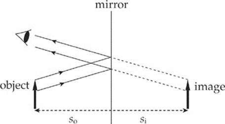
The figure below shows an object (denoted by a bold arrow) in front of a flat mirror. Light that”s reflected off of the object strikes the mirror and is reflected back to our eyes. The directions of the rays reflected off the mirror determine where we perceive the image to be.
There are four questions we”ll answer about the image formed by a mirror:
(1) Where is the image?
(2) Is the image real or is it virtual?
(3) Is the image upright or is it inverted?
(4) What is the height of the image (compared to that of the object)?
When we look at ourselves in a mirror, it seems like our image is behind the mirror, and, if we take a step back, our image also takes a step back. The Law of Reflection can be used to show that the image seems as far behind the mirror as the object is in front of the mirror. This answers question (1).
An image is said to be real if light rays actually focus at the image. A real image can be projected onto a screen. For a flat mirror, light rays bounce off the front of the mirror; so, of course, no light focuses behind it. Therefore, the images produced by a flat mirror are not real; they arevirtual. This answers question (2).
When we look into a flat mirror, our image isn”t upside down; flat mirrors produce upright images, and question (3) is answered.
Finally, the image formed by a flat mirror is neither magnified nor diminished (minified) relative to the size of the object. This answers question (4).
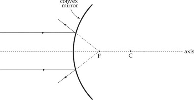
SPHERICAL MIRRORS
A spherical mirror is a mirror that”s curved in such a way that its surface forms part of a sphere.
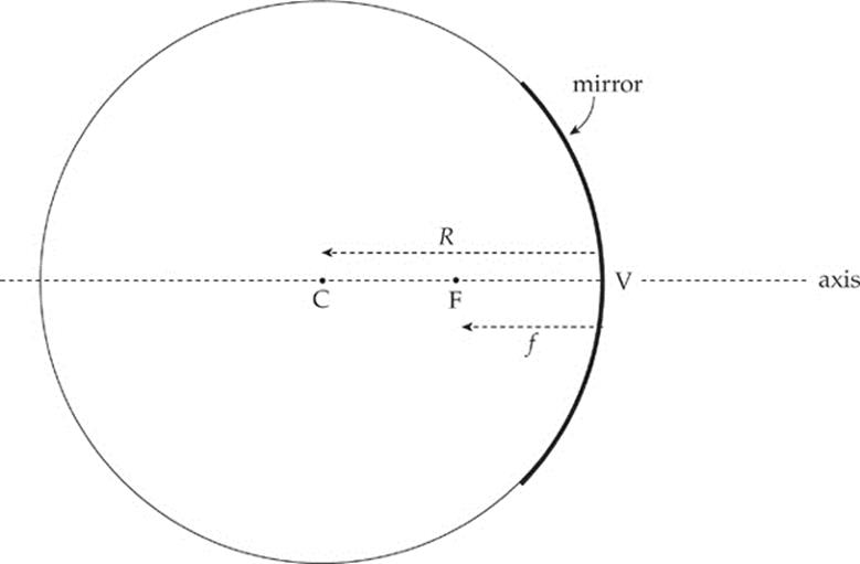
The center of this imaginary sphere is the mirror”s center of curvature, and the radius of the sphere is called the mirror”s radius of curvature, R. Halfway between the mirror and the center of curvature, C, is the focus (or focal point), F. The intersection of the mirror”s optic axis (its axis of symmetry) with the mirror itself is called the vertex, V, and the distance from V to F is called the focal length, f, equal to one-half of the radius of curvature:

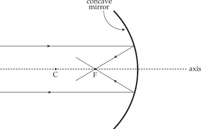
If the mirror had a parabolic cross-section, then any ray parallel to the axis would be reflected by the mirror through the focal point. Spherical mirrors do this for incident light rays near the axis (paraxial rays) because, in the region of the mirror that”s close to the axis, the shapes of a parabolic mirror and a spherical mirror are nearly identical.
The previous two figures illustrate a concave mirror, a mirror whose reflective side is caved in toward the center of curvature. The following figure illustrates the convex mirror, which has a reflective side curving away from the center of curvature.
RAY TRACING FOR MIRRORS
One method of answering the four questions listed above concerning the image formed by a mirror involves a geometric approach called ray tracing. Representative rays of light are sketched in a diagram that depicts the object and the mirror; the point at which the reflected rays intersect (or appear to intersect) is the location of the image. Some rules governing rays are:
Concave mirrors:
· An incident ray parallel to the axis is reflected through the focus.
· An incident ray that passes through the focus is reflected parallel to the axis.
· An incident ray that strikes the vertex is reflected at an equal angle to the axis.
Convex mirrors:
· An incident ray parallel to the axis is reflected away from the virtual focus.
· An incident ray directed toward the virtual focus is reflected parallel to the axis.
· An incident ray that strikes the vertex is reflected at an equal angle to the axis.
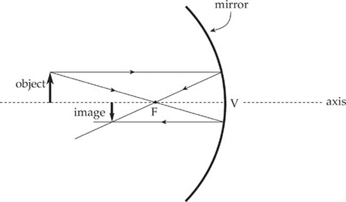
Example 16.10 The figure below shows a concave mirror and an object (the bold arrow). Use a ray diagram to locate the image of the object.
Solution. It only takes two distinct rays to locate the image:
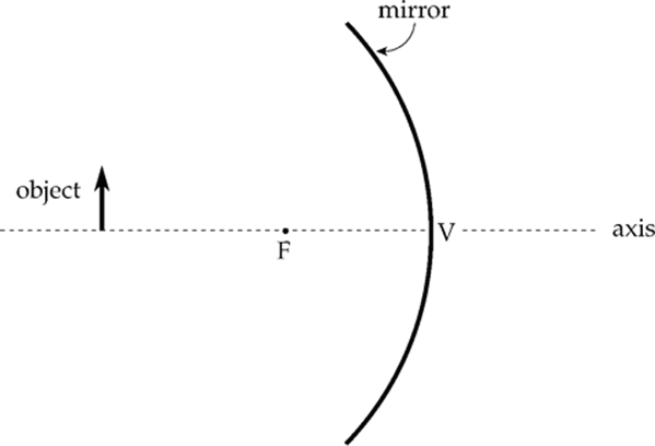
Example 16.11 The figure below shows a convex mirror and an object (the arrow). Use a ray diagram to locate the image of the object.
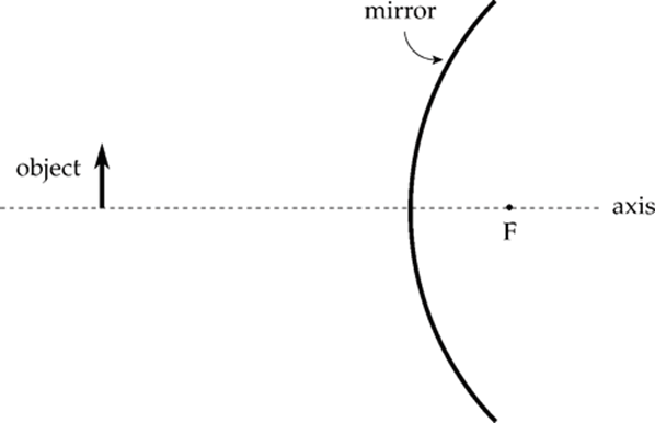
Solution.
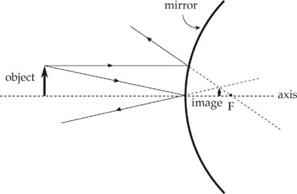
The ray diagrams of the preceding examples can be used to determine the location, orientation, and size of the image. The nature of the image—that is, whether it”s real or virtual—can be determined by seeing on which side of the mirror the image is formed. If the image is formed on the same side of the mirror as the object, then the image is real, but if the image is formed on the opposite side of the mirror, it”s virtual. Another way of looking at this is: if you had to trace lines back to form an image, that image is virtual. Therefore, the image in Example 16.10 is real, and the image in Example 16.11 is virtual.
USING EQUATIONS TO ANSWER QUESTIONS ABOUT THE IMAGE
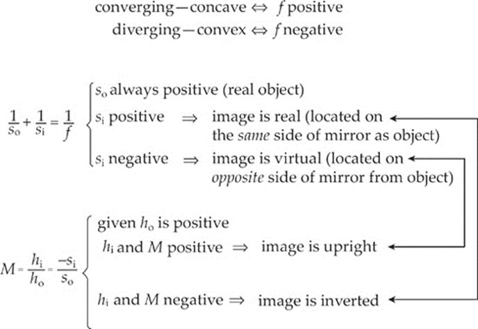
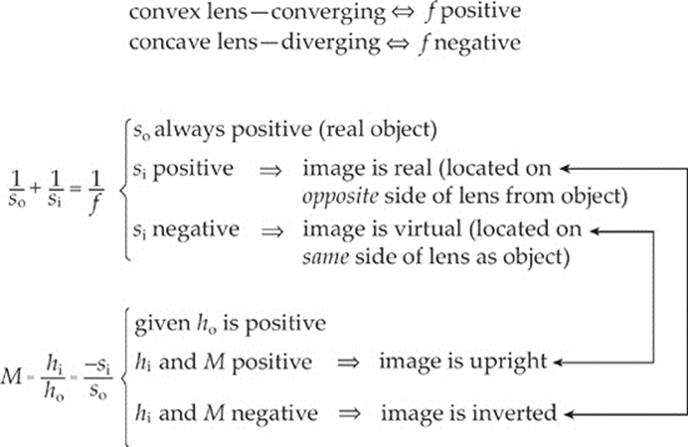
The fastest and easiest way to get information about an image is to use two equations and some simple conventions. The first equation, called the mirror equation, is
where so is the object”s distance from the mirror, si is the image”s distance from the mirror, and f is the focal length of the mirror. The value of so is always positive for a real object, but si can be positive or negative. The sign of si tells us whether the image is real or virtual: If si is positive, the image is real; and if si is negative, the image is virtual.
The second equation is called the magnification equation:
This gives the magnification; the height of the image, hi, is |M| times the height of the object, ho. If M is positive, then the image is upright relative to the object; if M is negative, it”s inverted. Because so is always positive, we can come to two important conclusions. If si is positive, then M is negative, so real images are always inverted, and, if si is negative, then M is positive, so virtual images are always upright.
Finally, to distinguish mathematically between concave and convex mirrors, we always write the focal length f as a positive value for concave mirrors and a negative value for convex mirrors. With these two equations and their accompanying conventions, all four questions about an image can be answered.
MIRRORS
Example 16.12 An object of height 4 cm is placed 30 cm in front of a concave mirror whose focal length is 10 cm.
(a) Where”s the image?
(b) Is it real or virtual?
(c) Is it upright or inverted?
(d) What”s the height of the image?
Solution.
(a) With so = 30 cm and f = 10 cm, the mirror equation gives

The image is located 15 cm in front of the mirror.
(b) Because si is positive, the image is real.
(c) Real images are inverted.
(d) 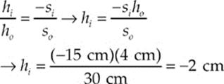
The –2 cm also confirms the image is inverted.
Example 16.13 An object of height 4 cm is placed 20 cm in front of a convex mirror whose focal length is –30 cm.
(a) Where”s the image?
(b) Is it real or virtual?
(c) Is it upright or inverted?
(d) What”s the height of the image?
Solution.
(a) With so = 20 cm and f = –30 cm, the mirror equation gives us:

So, the image is located 12 cm behind the mirror.
(b) Because si is negative, the image is virtual.
(c) Virtual images are upright.
(d) 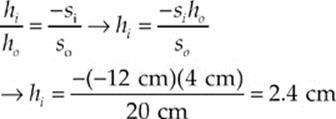
[The fact that the magnification is positive tells us that the image is upright, as we said in part (c).]
Example 16.14 Show how the statements made earlier about plane mirrors can be derived from the mirror and magnification equations.
Solution. A plane mirror can be considered a spherical mirror with an infinite radius of curvature (and an infinite focal length). If f = ∞, then 1/f = 0, so the mirror equation becomes
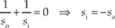
So, the image is as far behind the mirror as the object is in front. Also, since so is always positive, si is negative, so the image is virtual. The magnification is
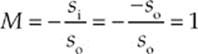
and the image is upright and has the same height as the object. The mirror and magnification equations confirm our description of images formed by plane mirrors.
Example 16.15 Show why convex mirrors can only form virtual images.
Solution. Because f is negative and so is positive, the mirror equation

immediately tells us that si cannot be positive (if it were, the left-hand side would be the sum of two positive numbers, while the right-hand side would be negative). Since si must be negative, the image must be virtual.
Example 16.16 An object placed 60 cm in front of a spherical mirror forms a real image at a distance of 30 cm from the mirror.
(a) Is the mirror concave or convex?
(b) What”s the mirror”s focal length?
(c) Is the image taller or shorter than the object?
Solution.
(a) The fact that the image is real tells us that the mirror cannot be convex, since convex mirrors form only virtual images. The mirror is concave.
(b) With so = 60 cm and si = 30 cm (si is positive since the image is real), the mirror equation tells us that

Note that f is positive, which confirms that the mirror is concave.
(c) The magnification is
Since the absolute value of M is less than 1, the mirror makes the object look smaller (minifies the height of the object). The image is only half as tall as the object (and is upside down, because M is negative).
Example 16.17 A concave mirror with a focal length of 25 cm is used to create a real image that has twice the height of the object. How far is the image from the mirror?
Solution. Since hi (the height of the image) is twice ho (the height of the object) the value of the magnification is either +2 or –2. To figure out which, we just notice that the image is real; real images are inverted, so the magnification, M, must be negative. Therefore, M = –2, so
Substituting this into the mirror equation gives us

THIN LENSES
A lens is an optical device that forms an image by refracting light. We”ll now talk about the equations and conventions that are used to analyze images formed by the two major categories of lenses: converging and diverging.
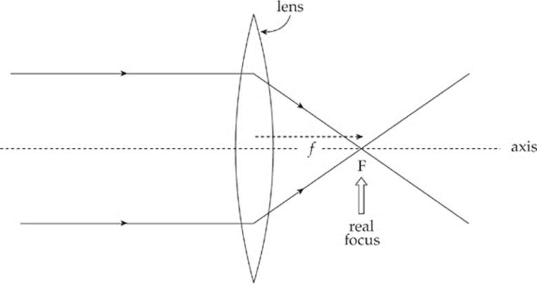
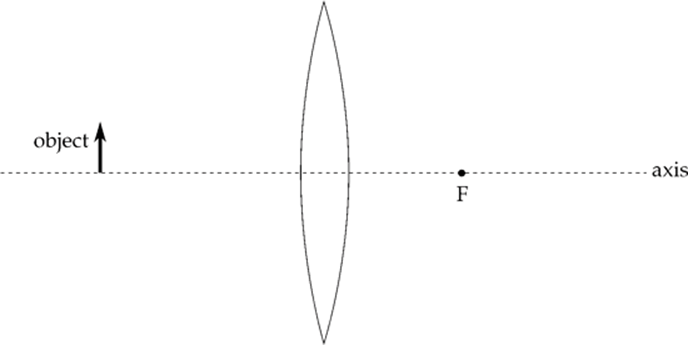
A converging lens—like the bi-convex one shown below—converges parallel paraxial rays of light to a focal point on the far side. (This lens is bi-convex; both of its faces are convex. Converging lenses all have at least one convex face.) Because parallel light rays actually focus at F, this point is called a real focus. Its distance from the lens is the focal length, f.
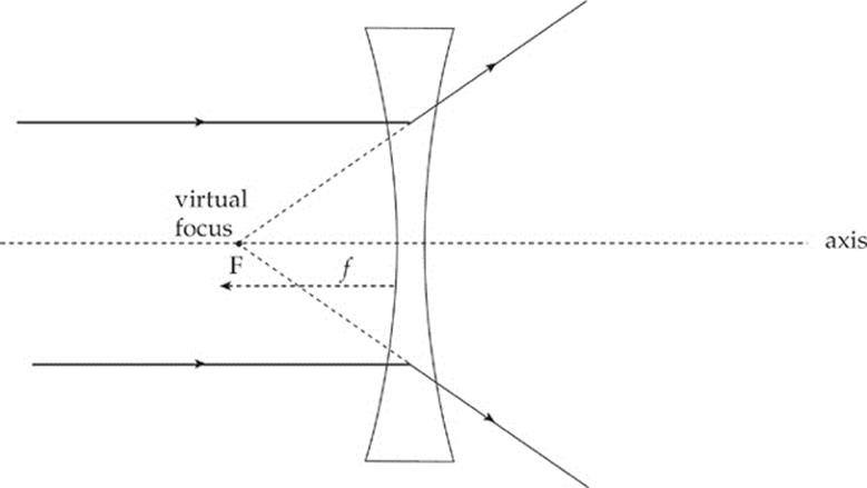
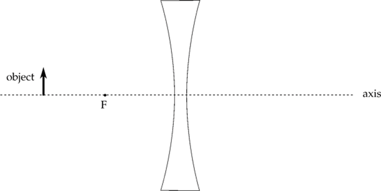
A diverging lens—like the bi-concave one shown below—causes parallel paraxial rays of light to diverge away from a virtual focus, F, on the same side as the incident rays. (Diverging lenses all have at least one concave face.)
RAY TRACING FOR LENSES
Just as is the case with mirrors, representative rays of light can be sketched in a diagram along with the object and the lens; the point at which the reflected rays intersect (or appear to intersect) is the location of the image. The rules that govern these rays are as follows:
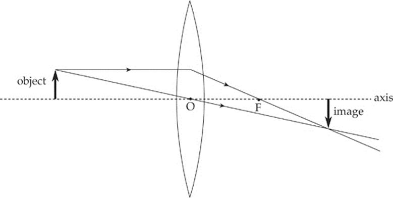
Converging lenses:
· An incident ray parallel to the axis is refracted through the real focus.
· Incident rays pass undeflected through the optical center, O (the central point within the lens where the axis intersects the lens).
Diverging lenses:
· An incident ray parallel to the axis is refracted away from the virtual focus.
· Incident rays pass undeflected through the optical center, O.
Example 16.18 The figure below shows a converging lens and an object (denoted by the bold arrow). Use a ray diagram to locate the image of the object.
Solution.
Example 16.19 The figure below shows a diverging lens and an object. Use a ray diagram to locate the image of the object.
Solution.

The nature of the image—that is, whether it”s real or virtual—is determined by the side of the lens upon which the image is formed. If the image is formed on the side of the lens that”s opposite the object, then the image is real, and if the image is formed on the same side of the lens as the object, then it”s virtual. Another way of looking at this is: If you had to trace lines back to form an image, that image is virtual. Therefore, the image in Example 16.18 is real, while the image in Example 16.19 is virtual.
USING EQUATIONS TO ANSWER QUESTIONS ABOUT THE IMAGE
Lenses and mirrors use the same equations, notation, and sign conventions, with the following note. Converging optical devices (+f) are concave mirrors and convex lenses. Diverging optical devices (–f) are convex mirrors and concave lenses.
LENSES
Example 16.20 An object of height 11 cm is placed 44 cm in front of a converging lens with a focal length of 24 cm.
(a) Where”s the image?
(b) Is it real or virtual?
(c) Is it upright or inverted?
(d) What”s the height of the image?
Solution.
(a) With so = 44 cm and f = 24 cm, the lens equation gives us:

So, the image is located 53 cm from the lens, on the opposite side from the object.
(b) Because si is positive, the image is real.
(c) Real images are inverted.
(d) 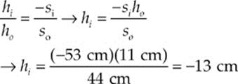
The negative hi reaffirms that we have an inverted image. These results are illustrated in Example 16.18.
Example 16.21 An object of height 11 cm is placed 48 cm in front of a diverging lens with a focal length of –24.5 cm.
(a) Where”s the image?
(b) Is it real or virtual?
(c) Is it upright or inverted?
(d) What”s the height of the image?
Solution.
(a) With so = 48 cm and f = –24.5 cm, the lens equation gives us:

The image is 16 cm from the lens, on the same side as the object.
(b) Because si is negative, the image is virtual.
(c) Virtual images are upright.
(d) 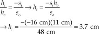
These results are illustrated in Example 16.19.
Example 16.22 The power of a lens, P, is defined as 1/f, where f is the lens”s focal length (in meters). Lens power is expressed in diopters (abbreviated D), where 1 D = 1 m–1. When an object is placed 10 cm from a converging lens, the real image formed is twice the height of the object. What”s the power of this lens?
Solution. Since hi, the height of the image, is twice ho, the height of the object, the value of the magnification is either +2 or –2. To decide, we simply notice that the image is real; real images are inverted, so the magnification, m, must be negative. Since m = –2, we find that
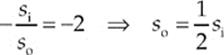
Because so = 10 cm, it must be true that si = 20 cm, so the lens equation gives us:
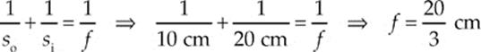
Expressing the focal length in meters and then taking the reciprocal gives the lens power in diopters:
CHAPTER 16 REVIEW QUESTIONS
Solutions can be found in Chapter 18.
SECTION I: MULTIPLE CHOICE
1. What is the wavelength of an X-ray whose frequency is 1.0 × 10¹⁸ Hz?
(A) 3.3 × 10⁻¹¹ m
(B) 3.0 × 10⁻¹⁰ m
(C) 3.3 × 10⁻⁹ m
(D) 3.0 × 10⁻⁸ m
(E) 3.0 × 1026 m
2. In Young”s double-slit interference experiment, what is the difference in path length of the light waves from the two slits at the center of the first bright fringe above the central maximum?
(A) 0
(B) ![]() λ
λ
(C) ![]() λ
λ
(D) λ
(E) ![]() λ
λ
3. A beam of light in air is incident upon the smooth surface of a piece of flint glass, as shown:
If the reflected beam and refracted beam are perpendicular to each other, what is the index of refraction of the glass?
(A) ![]()
(B) ![]()
(C) ![]()
(D) 2
(E) 2![]()
4. When green light (wavelength = 500 nm in air) travels through diamond (refractive index = 2.5), what is its wavelength?
(A) 200 nm
(B) 300 nm
(C) 500 nm
(D) 1000 nm
(E) 1250 nm
5. A beam of light traveling in Medium 1 strikes the interface to another transparent medium, Medium 2. If the speed of light is less in Medium 2 than in Medium 1, the beam will
(A) refract toward the normal.
(B) refract away from the normal.
(C) undergo total internal reflection.
(D) have an angle of reflection smaller than the angle of incidence.
(E) have an angle of reflection greater than the angle of incidence.
6. If a clear liquid has a refractive index of 1.45 and a transparent solid has an index of 2.90 then, for total internal reflection to occur at the interface between these two media, which of the following must be true?
|
incident beam originates in |
at an angle of incidence greater than |
|
|
(A) |
the solid |
30° |
|
(B) |
the liquid |
30° |
|
(C) |
the solid |
60° |
|
(D) |
the liquid |
60° |
|
(E) |
Total internal reflection cannot occur. |
|
7. An object is placed 60 cm in front of a concave spherical mirror whose focal length is 40 cm. Which of the following best describes the image?
|
Nature of image |
Distance from mirror |
|
|
(A) |
Virtual |
24 cm |
|
(B) |
Real |
24 cm |
|
(C) |
Virtual |
120 cm |
|
(D) |
Real |
120 cm |
|
(E) |
Real |
240 cm |
8. An object is placed 60 cm from a spherical convex mirror. If the mirror forms a virtual image 20 cm from the mirror, what”s the magnitude of the mirror”s radius of curvature?
(A) 7.5 cm
(B) 15 cm
(C) 30 cm
(D) 60 cm
(E) 120 cm
9. The image created by a converging lens is projected onto a screen that”s 60 cm from the lens. If the height of the image is 1/4 the height of the object, what”s the focal length of the lens?
(A) 36 cm
(B) 45 cm
(C) 48 cm
(D) 72 cm
(E) 80 cm
10. Which of the following is true concerning a bi-concave lens? (A bi-concave lens has both surfaces concave.)
(A) Its focal length is positive.
(B) It cannot form real images.
(C) It cannot form virtual images.
(D) It can magnify objects.
(E) None of the above
SECTION II: FREE RESPONSE
1. Two trials of a double-slit interference experiment are set up as follows. The slit separation is d = 0.50 mm, and the distance to the screen, L, is 4.0 m.
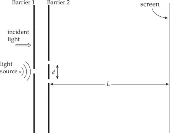
(a) What is the purpose of the first (single-slit) barrier? Why not use two light sources, one at each slit at the second barrier? Explain briefly.
In the first trial, white light is used.
(b) What is the vertical separation on the screen (in mm) between the first-order maxima for red light (λ = 750 nm) and violet light (λ = 400 nm)?
(c) Locate the nearest point to the central maximum where an intensity maximum for violet light (λ = 400 nm) coincides with an intensity maximum for orange-yellow light (λ = 600 nm).
In the second trial, the entire region between the double-slit barrier and the screen is filled with a large slab of glass of refractive index n = 1.5, and monochromatic green light (λ = 500 nm in air) is used.
(d) What is the separation between adjacent bright fringes on the screen?
2. In order to determine the criteria for constructive and destructive interference, the following rules are used:
i) When light strikes the boundary to a medium with a higher refractive index than the incident medium, it undergoes a 180° phase change upon reflection (this is equivalent to a shift by one-half wavelength).
ii) When light strikes the boundary to a medium with a lower refractive index than the incident medium, it undergoes no phase change upon reflection.
These rules can be applied to the two situations described below.
A thin soap film of thickness T, consisting of a mixture of water and soap (refractive index = 1.38), has air on both sides. Incident sunlight is reflected off the front face and the back face, causing interference.
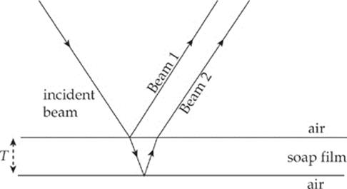
(a) Which beam, 1 or 2, suffers a 180° phase change upon reflection?
(b) Since the beams are out of phase, destructive interference will occur if the difference in their path lengths, ∆![]() ≈ 2T for near-normal incidence, is equal to a whole number of wavelengths (wavelength as measured in the soap film). What is the criterion for constructive interference? Write your answer as an algebraic equation.
≈ 2T for near-normal incidence, is equal to a whole number of wavelengths (wavelength as measured in the soap film). What is the criterion for constructive interference? Write your answer as an algebraic equation.
3. An object of height 5 cm is placed 40 cm in front of a spherical concave mirror. An image is formed 72 cm behind the mirror.
(a) Is the image real or virtual?
(b) Is the image upright or inverted?
(c) What”s the height of the image?
(d) What is the mirror”s radius of curvature?
(e) In the figure below, sketch the mirror, labeling its vertex and focal point, and then construct a ray diagram (with a minimum of two rays) showing the formation of the image.
SUMMARY
· All electromagnetic waves travel at the speed of light (c= 3 × 10⁸ m/s). They obey the wave equation v = fλ. When monochromatic coherent light goes through double slits (or a diffraction grating) there will be constructive interference when the path difference is given by PD = mλ or dsinθ = mλ where m = 0, 1, 2…. There will be destructive interference for PD = (m+![]() ) λ or d sinθ = (m+
) λ or d sinθ = (m+![]() )λ. For small angles we can say xm =
)λ. For small angles we can say xm = ![]() , where xm is the distance the mth maximum is located from the central maximum and shows where constructive interference occurs.
, where xm is the distance the mth maximum is located from the central maximum and shows where constructive interference occurs.
· Geometric optics always measures angles from the normal line. Topics include the fact that the angle of incidence is equal to the angle of reflection and that these angles lie in the same plane.
· Snell”s Law states when light enters a new medium (material) it changes speeds and may change directions. This is stated in the formula
n1 sin θ1 = n2 sin θ2
· where n is the index of refraction, which is a ratio of the speed of light in a vacuum to the speed of light in the substance (n = ![]() ). The index of refraction is always greater than 1 and has no units. When going from a high index of refraction to a lower index of refraction, light may have total internal reflection if the angle is larger than the critical angle (sin θc =
). The index of refraction is always greater than 1 and has no units. When going from a high index of refraction to a lower index of refraction, light may have total internal reflection if the angle is larger than the critical angle (sin θc = ![]() ).
).
· For both thin lenses and curved mirrors you can use the thin lens equation: 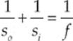
Where f is positive for a convex lens or a concave mirror and f is negative for a concave lens or a convex mirror s0 is always positive.
· For a lens, if si is negative the lens image is virtual and located on the same side of the lens as the object. If si is positive, the lens image is real and located on the opposite side of the lens from the object.
· For a mirror, if si is negative, the image is virtual and located on the opposite side of the mirror from the object. If si is positive, the image is real and located on the same side of the mirror as the object.
· The magnification of a lens is given by M =  .
.
· A diverging optical device could be either a convex mirror or a concave lens. The thing these two have in common is that no matter where the object is located they form images that are virtual and upright. The sign of hi will always be positive and the sign of si will always be negative. The sign of the magnification will be positive and its value will be less than one. The image will always be located between the focal length and the optical device.
· A converging optical device could be either a concave mirror or a convex lens. The thing these two have in common is that when so is outside the focal length they form images that are real and inverted. The sign of hi will be negative and the sign of si will be positive. The sign of the magnification will be negative and its absolute value can be any number greater than zero. The other thing they have in common is that when so is inside the focal length they form images that are virtual and upright. The sign of hi will be positive and the sign of si will be negative. The sign of the magnification will be positive and its value will be greater than one.