SAT Physics Subject Test
Chapter 10 Direct Current Circuits
CIRCUIT ANALYSIS
We will now develop a way of specifying the current, voltage, and power associated with each element in a circuit. Our circuits will contain three basic elements: batteries, resistors, and connecting wires. As we”ve seen, the resistance of an ordinary metal wire is negligible; resistance is provided by devices that control the current: resistors.
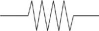
All the resistance of the system is concentrated in resistors, which are symbolized in a circuit diagram by this symbol
Batteries are denoted by the symbol
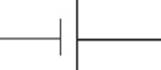
where the longer line represents the positive (higher potential) terminal, and the shorter line is the negative (lower potential) terminal.
Here”s a simple circuit diagram.
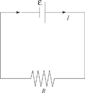
The emf (ε) of the battery is indicated, as is the resistance (R) of the resistor. It”s easy to determine the current in this case because there”s only one resistor. The equation V = IR, with V given by ε, gives us
I = ![]()
Combinations of Resistors
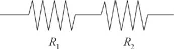
As you remember from chapter 9, two common ways of combining circuit elements within a circuit is to place them either in series (one after the other)
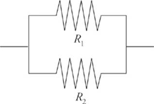
or in parallel (that is, side-by-side)
To simplify the circuit, our goal is to find the equivalent resistance of the resistors. Resistors are said to be in series if they all share the same current and if the total voltage drop across them is equal to the sum of the individual voltage drops.
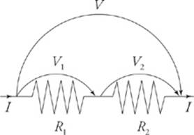
In this case, then, if V denotes the voltage drop across the combination, we have
This idea can be applied to any number of resistors in series (not just two).
Rs = R1 + R2 + …
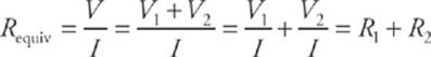
Resistors are said to be in parallel if they all share the same voltage drop, and the total current entering the combination is split among the resistors. Imagine that a current I enters the combination. It splits; some of the current, I1, would go through R1, and the remainder, I2, would go throughR2.
What”s the same?
Remember, in a series
circuit the current is the
same through each
resistor. In parallel, the
voltage drop is the same.
So if V is the voltage drop across the combination, we have
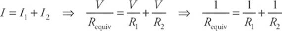
This idea can be applied to any number of resistors in parallel (not just two). The reciprocal of the equivalent resistance for resistors in parallel is equal to the sum of the reciprocals of the individual resistances.
Notice that the equation for the equivalent resistance for resistors in series is just like the equation for the equivalent capacitance for capacitors in parallel and vice versa. So be careful with series and parallel resistors versus capacitors—the formulas are the reverse of each other.
![]()
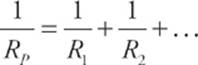
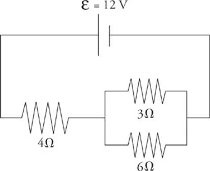
2. Calculate the equivalent resistance for the following circuit:
Here”s How to Crack It
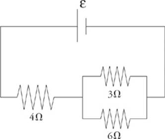
First find the equivalent resistance of the two parallel resistors.
This resistance is in series with the 4 Ω resistor, so the overall equivalent resistance in the circuit is Requiv = 4 Ω + 2 Ω = 6 Ω.
![]()
![]()
3. Determine the current through each resistor, the voltage drop across each resistor, and the power given off (dissipated) as heat in each resistor of the circuit below.
Here”s How to Crack It
You might want to redraw the circuit each time we replace a combination of resistors by its equivalent resistance. From our work in the last question, we have
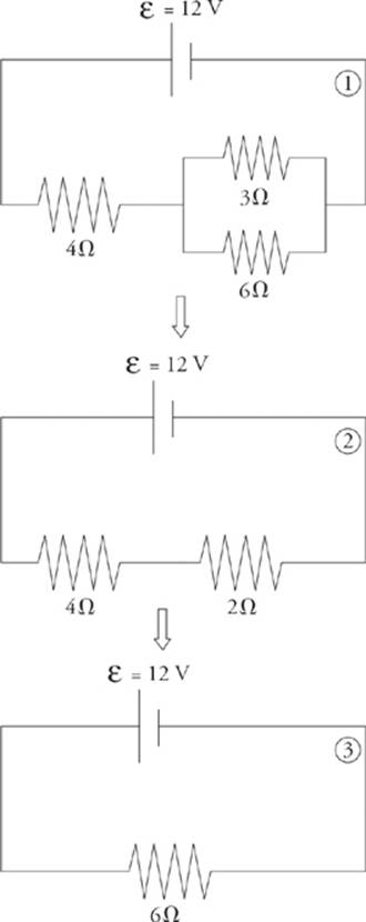
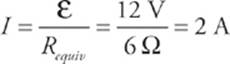
From diagram ![]() , which has just one resistor, we can figure out the current.
, which has just one resistor, we can figure out the current.
Now we can work our way back to the original circuit (diagram ![]() ). In going from
). In going from ![]() to
to ![]() , we are going back to a series combination. Resistors in series share the same current, so we take the current, I = 2 A, back to diagram
, we are going back to a series combination. Resistors in series share the same current, so we take the current, I = 2 A, back to diagram ![]() . The current through each resistor in diagram
. The current through each resistor in diagram ![]() is 2 A.
is 2 A.
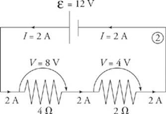
Since we know the current through each resistor, we can figure out the voltage drop across each resistor using the equation V = IR. The voltage drop across the 4 Ω resistor is (2 A)(4 Ω) = 8 V, and the voltage drop across the 2 Ω resistor is (2 A)(2 Ω) = 4 V. Notice that the total voltage drop across the two resistors is 8 V + 4 V = 12 V, which matches the emf of the battery.
Now for the last step: going from diagram ![]() back to diagram
back to diagram ![]() . Nothing needs to be done with the 4 Ω resistor; nothing about it changes in going from diagram
. Nothing needs to be done with the 4 Ω resistor; nothing about it changes in going from diagram ![]() to
to ![]() , but the 2 Ω resistor in diagram
, but the 2 Ω resistor in diagram ![]() goes back to the parallel combination. Resistors in parallel share the same voltage drop. So we take the voltage drop, V = 4 V, back to diagram
goes back to the parallel combination. Resistors in parallel share the same voltage drop. So we take the voltage drop, V = 4 V, back to diagram ![]() . The voltage drop across each of the two parallel resistors in diagram
. The voltage drop across each of the two parallel resistors in diagram ![]() is 4 V.
is 4 V.
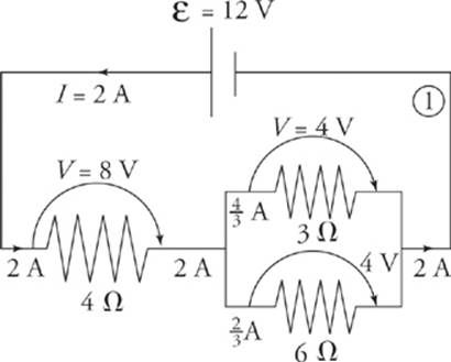
Since we know the voltage drop across each resistor, we can figure out the current through each resistor by using the equation I = ![]() The current through the 3 Ω resistor is
The current through the 3 Ω resistor is  , and the current through the 6 Ω resistor is
  . Notice that the current entering the parallel combination (2 A) equals the total current passing through the individual resistors
  .
.
Finally, we will calculate the power dissipated as heat by each resistor. We can use any of the equivalent formulas: P = IV, P = I2R, or P = V2/R.
For the 4 Ω resistor: P = IV = (2 A)(8 V) = 16 W
For the 3 Ω resistor: P = IV = (![]() A)(4 V) =
A)(4 V) = ![]() W
W
For the 6 Ω resistor: P = IV = (![]() A)(4 V) =
A)(4 V) = ![]() W
W
So the resistors are dissipating a total of
16 W + ![]() W +
W + ![]() W = 24 W.
W = 24 W.
If the resistors are dissipating a total of 24 J every second, then they must be provided with that much power. This is easy to check: P = IV = (2 A)(12 V) = 24 W.
![]()
![]()
Questions 4-7
For the circuit below,
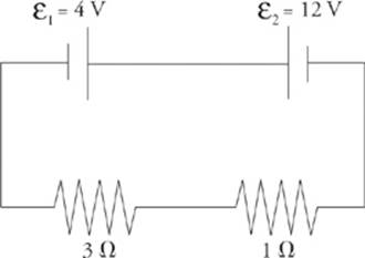
4. In which direction will current flow and why?
5. What”s the overall emf?
6. What”s the current in the circuit?
7. At what rate is energy consumed by, and provided to, this circuit?
Here”s How to Crack It
4. The battery whose emf is ε1 wants to send current clockwise, while the battery whose emf is ε2 wants to send current counterclockwise. Since ε2 > ε1, the battery whose emf is ε2 is the more powerful battery, so the current will flow counterclockwise.
5. Charges forced through ε1 will lose, rather than gain, 4 V of potential, so the overall emf of this circuit is ε2 – ε1 = 8 V.
6. Since the total resistance is 3 Ω + 1 Ω = 4 Ω, the current will be I = ![]() = 2A.
= 2A.
7. Finally, energy will be dissipated in these resistors at a rate of I2R1+ I2R2 = (2 A)2 (3 Ω) + (2 A)2(1 Ω) = 16 W. ε2 will provide energy at a rate of P2 = IV2 = (2 A)(12 V) = 24 W, while 1 will absorb at a rate of P1 = IV1 = (2 A)(4 V) = 8 W. Once again, energy is conserved; the power delivered (24 W) equals the power taken (8 W + 16 W = 24 W).
![]()
![]()
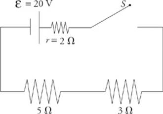
8. All real batteries contain internal resistance, r. Determine the current in the following circuit when the switch S is closed:
Here”s How to Crack It
Before the switch is closed, there is no complete conducting pathway from the positive terminal of the battery to the negative terminal, so no current flows through the resistors. However, once the switch is closed, the resistance of the circuit is 2 Ω + 3 Ω + 5 Ω = 10 Ω, so the current in the circuit is I = ![]() = 2A. Often the battery and its internal resistance are enclosed in a dotted line. See the following example.
= 2A. Often the battery and its internal resistance are enclosed in a dotted line. See the following example.
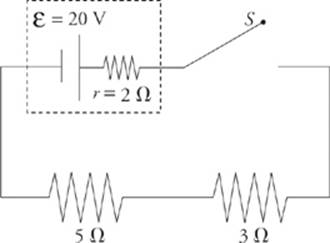
In this case, a distinction can be made between the emf of the battery and the actual voltage it provides once the current has begun. Since I = 2 A, the voltage drop across the internal resistance is Ir = (2 A)(2 Ω) = 4 V, so the effective voltage provided by the battery to the rest of the circuit—called the terminal voltage—is lower than the ideal emf. It is V = – Ir = 20 V – 4 V = 16 V.
![]()
![]()
9. A student has three 30 Ω resistors and an ideal 90 V battery. (A battery is ideal if it has a negligible internal resistance.) Compare the current drawn from—and the power supplied by—the battery when the resistors are arranged in parallel versus in series.
Here”s How to Crack It
Resistors in series always provide an equivalent resistance that”s greater than any of the individual resistances, and resistors in parallel always provide an equivalent resistance that”s smaller than their individual resistances. So, hooking up the resistors in parallel will create the smallest resistance and draw the greatest total current.
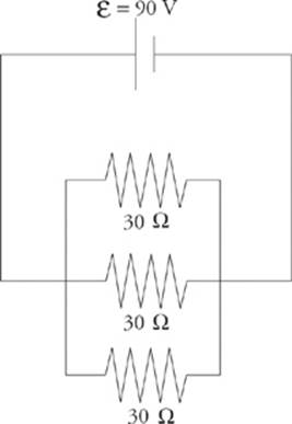
In this case, the equivalent resistance is

and the total current is 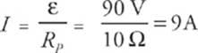 . (You could verify that 3 A of current would flow in each of the three branches of the combination.) The power supplied by the battery will be P = IV = (9 A)(90 V) = 810 W.
If the resistors are in series, the equivalent resistance is RS = 30 Ω + 30 Ω + 30 Ω = 90 Ω, and the current drawn is only 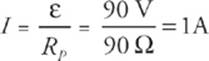 . The power supplied by the battery in this case is just P = IV = (1 A)(90 V) = 90 W.
![]()
![]()
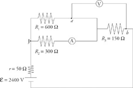
10. A voltmeter is a device that”s used to measure the voltage between two points in a circuit. An ammeter is used to measure current. Determine the readings on the voltmeter (denoted ![]() ) and the ammeter (denoted
) and the ammeter (denoted ![]() ) in the circuit below.
) in the circuit below.
Here”s How to Crack It
Assume that the ammeter is ideal; it has negligible resistance and doesn”t alter the current that it”s trying to measure. Similarly, assume that the voltmeter has an extremely high resistance, so it draws negligible current away from the circuit.
Our first goal is to find the equivalent resistance in the circuit. The 600 Ω and 300 Ω resistors are in parallel; they”re equivalent to a single 200 Ω resistor. This is in series with the battery”s internal resistance, r, and R3. The overall equivalent resistance is therefore Requiv = 50 Ω + 200 Ω + 150 Ω = 400 Ω, so the current supplied by the battery is 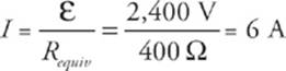 . At the junction marked J, this current splits. Since R1 is twice R2, half as much current will flow through R1 as through R2; the current through R1 is I1 = 2 A, and the current through R2 is I2 = 4 A. The voltage drop across each of these resistors is I1R1 = I2R2 = 1,200 V (matching voltages verify the values of currents I1 and I2). Since the ammeter is in the branch that contains R2, it will read I2 = 4 A.
The voltmeter will read the voltage drop across R3, which is V3 = IR3 = (6 A)(150 Ω) = 900 V. So the potential at point b is 900 V lower than at point a.
![]()
![]()
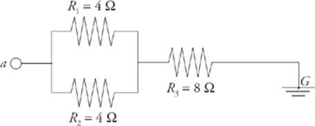
11. The diagram below shows a point a at potential V = 20 V connected by a combination of resistors to a point (denoted G) that is grounded. The ground is considered to be at potential zero. If the potential at point a is maintained at 20 V, what is the current through R3 ?
Here”s How to Crack It
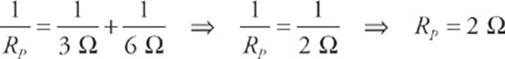
R1 and R2 are in parallel; their equivalent resistance is RP, where
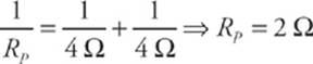
RP is in series with R3, so the equivalent resistance is
Requiv = RP + R3 = (2 Ω) + (8 Ω) =10 Ω
and the current that flows through R3 is
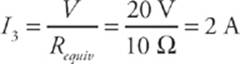
![]()