SAT Subject Test Physics (2012)
PART III. PHYSICS TOPIC REVIEW
Chapter 13. CURRENT AND CIRCUITS
In the previous chapter, you reviewed static electricity, or the buildup of charge. Under the right conditions, charges can be made to flow as current electricity. In this chapter, you will review current electricity and types of circuits.
Voltage
In the previous chapter, you briefly reviewed potential difference, or voltage. A battery is a device that has a voltage across its terminals. When a battery is connected to a bulb by wires, a charge begins to flow from one terminal through the wires and bulb and back to the other terminal of the battery. As you learned, the charges that “move” are actually electrons.
One terminal, the positive terminal, has a deficiency of electrons. The other terminal, the negative terminal, has an excess of electrons. This difference was set up by work done against the force of repulsion. Recall that work per unit charge is potential difference (V).
Current
The amount of charge moving through a conductor per second is known as current. The unit of current is the coulomb per second, or ampere. The symbol I is used to represent current. Even though it is electrons that are considered to be the carriers of charge, the convention for a long time has been to take the direction of the current as if it were positive charges that flow. This is, therefore, known as conventional current and is generally used to describe current flow on SAT Physics.
Current does not flow unimpeded by conductors. The opposition to the flow of charges offered by a material is known as its resistance. The unit of resistance is the ohm (Ω). It may help to think of resistance as friction through conductors.
Resistance depends on several factors, including the type of material, length, temperature, and cross-sectional area. Resistance is lower in conductors and higher in insulators. Resistance is directly proportional to length, meaning that resistance increases as length increases. Generally, resistance increases with temperature. It is inversely proportional to the cross-sectional area, which means that resistance increases as a wire becomes thinner.
The relationship among current, resistance, and voltage is described by Ohm’s Law, which states that resistance is directly proportional to voltage and indirectly proportional to current.
![]()
You may also see or need to use the relationship in different formats.
![]()
Circuits
Current requires a complete path known as a circuit through which to travel. The resistors in a circuit can be arranged in series, in parallel, or some combination of the two.
Series Circuit A series circuit is one in which two or more resistors are arranged in such a way that the same current passes through each of them.
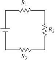
• The total resistance is the sum of the individual resistances.
![]()
• The same current passes through all the resistors.
![]()
The total current is found by dividing the total voltage by the total resistance.
![]()
• The voltage is divided among the resistances.
![]()
The total voltage is then the sum of the individual voltages.
![]()
Example:
Three resistors of 10 Ω, 20 Ω, and 30 Ω are connected in series with a 12-V battery.
(A) What is the total resistance?
(B) What current flows through the circuit?
![]()
![]()
Parallel Circuit A parallel circuit is one in which two or more resistors are arranged in such a way that current has more than one path through which to flow and each resistor has the same potential difference across it.
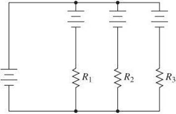
• The total resistance is the inverse sum of the inverse resistances.
![]()
• The total current is the sum of the currents through each resistor.
![]()
• The voltage across each resistance is the same.
![]()
Example:
Three resistors of 3 kΩ, 6 kΩ, and 12 kΩ are connected in series with a 12-V battery.
(A) What is the total resistance?
(B) What is the total current?


Combination Circuits A combination circuit is one that includes elements of both series circuits and parallel circuits.
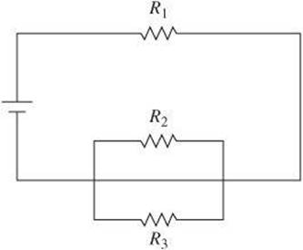
• To find the total resistance of the circuit, first find the equivalent resistance of R2 and R3. Then treat the equivalent resistance as if it were in series with R1. Suppose, for example, R1 is 10 Ω, R2is 20 Ω, and ![]() . The equivalent resistance of R2 and R3 is as follows
. The equivalent resistance of R2 and R3 is as follows
![]()
so ![]() .
.
![]()
• The total current is found by Ohm’s Law:
![]()
Suppose the voltage in this circuit is 12 V.
![]()
• The voltage across each resistor is found separately because the voltage supplied by the battery is divided proportionally between the parallel combination and R1.
![]()
The voltage across the parallel portion of the circuit must therefore be the difference between this voltage and the voltage supplied by the battery, or 6.5 V.
Circuit Measurements
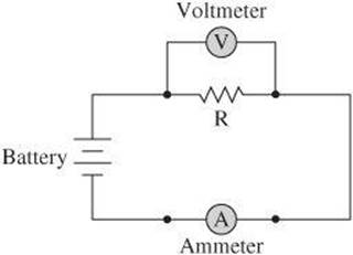
You have been calculating measurements of current through a resistor and voltage across a resistor. To actually measure the values, you can use devices placed within the circuit. An ammeter is a device used to measure current. It must be placed in a circuit in series with a resistor so that the same current passing through the resistor passes through the ammeter. An ammeter has a low resistance so that it does not significantly change the total resistance of the circuit.
A voltmeter is a device used to measure voltage. It is placed in parallel with a resistor so that the voltage across the resistor is the same as the voltage across the voltmeter. A voltmeter has a high resistance so that current will not bypass the resistor by traveling through it.
Heating and Power
Whenever energy flows through a resistor, some heat is produced. The amount of heat depends on the current, the resistance, and the time it takes for current to flow through the resistor. These quantities are related in the following equation, in which the heat produced H in joules is directly proportional to the square of the current I in amperes, the resistance R in ohms, and the time in seconds. This relationship is known as Joule’s Law of Heating.
![]()
Recall that power is the rate at which work is done or energy is transferred. Power in an electric circuit can be described by the following equations, in which P is power, I is the current through a resistor, V is the voltage across a resistor, and R is the resistance.
![]()
Capacitors
If two conducting plates are connected to a battery, charge flows from the battery to the plates. One plate becomes positively charged and the other becomes negatively charged. The plates form a capacitor, which stores charge. A capacitor consists of two conductors separated by an insulator. That insulator could be air, oil, paper, or other materials known as dielectrics.
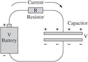
The capacitance C is the charge per unit voltage of the plates and is represented by the following equation, in which q is the charge of one of the plates and V is the voltage across the plates.
![]()
When Q is measured in Coulombs and V is measured in volts, the unit of capacitance is the farad F. One farad is a large unit of capacitance. Typical units of capacitance are microfarads and picofarads.
The charge on a capacitor does not change instantaneously. The change in charge occurs over time interval Δt.
![]()
Charge flowing into a capacitor builds up rather than passing through it. That charge cannot build up indefinitely. Instead, the charge builds up until the voltage balances the external voltage pushing charge on the capacitor.
Test-Taking Hint
Practice solving problems involving different types of circuits. Begin with the basic series and parallel circuits, and then work with combination circuits. Once you become familiar with the processes for finding current, voltage, and resistance, you can apply it to any circuit you encounter.
REVIEW QUESTIONS
Select the choice that best answers the question or completes the statement.
1. A radio with a resistance of 40Ω has a current of 0.1 A flowing through it. What is the voltage?
(A) 0.4 A
(B) 2.5 A
(C) 1.0 A
(D) 4.0 A
(E) 4.3 A
2. What is the value of a resistor that would limit the current in a circuit to 0.02 A when connected to an 8-V power supply?
(A) 160 Ω
(B) 250 Ω
(C) 400 Ω
(D) 460 Ω
(E) 650 Ω
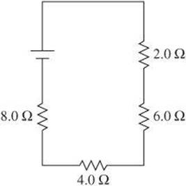
3. What is the equivalent resistance of the circuit below?
(A) 0.96 Ω
(B) 5.0 Ω
(C) 12 Ω
(D) 20.0 Ω
(E) 40.0 Ω
4. Two resistors are connected in series in a circuit. The same two resistors are connected in parallel in another circuit. Which statement about the circuits is true?
(A) the equivalent resistance of the series circuit is greater than in the parallel circuit.
(B) the resistors in series will have the same potential difference across them.
(C) the equivalent resistance in parallel must be less than the resistance in series.
(D) the total current in parallel will be the same through each resistor.
(E) the equivalent resistance of both circuits will be identical.
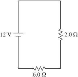
5. What is the voltage across the 6.0-Ω resistor?
(A) 4.5 V
(B) 8.0 V
(C) 9.0 V
(D) 12.5 V
(E) 16.0 V
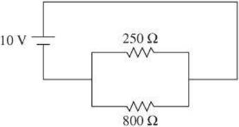
6. Which current will flow through the 250-Ω resistor in the circuit below?
(A) 10 mA
(B) 40 mA
(C) 50 mA
(D) 125 mA
(E) 250 mA
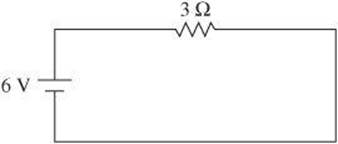
7. What is the power dissipated in the resistor of the circuit shown below?
(A) 2 W
(B) 3 W
(C) 6 W
(D) 9 W
(E) 12 W
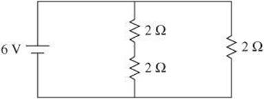
8. What is the equivalent resistance of the circuit?
(A) 0.2 Ω
(B) 0.5 Ω
(C) 1.3 Ω
(D) 1.8 Ω
(E) 2.0 Ω
Questions 9 and 10 relate to the diagram below, which shows an electric circuit. A current of 6 A passes through R1.
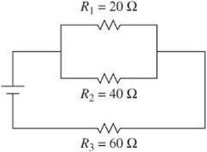
9. What is the potential difference across R1?
(A) 30 V
(B) 60 V
(C) 80 V
(D) 120 V
(E) 160 V
10. What is the rate at which R1uses electrical energy?
(A) 120 W
(B) 144 W
(C) 360 W
(D) 600 W
(E) 720 W
QUESTION ANSWERS AND EXPLANATIONS
1. D The problem can be solved using Ohm’s Law: ![]() .
.
2. C The problem can be solved using Ohm’s Law: ![]() .
.
3. D The total resistance for a series circuit is the sum of the individual resistances. ![]() .
.
4. A The only accurate statement is A. In the series circuit, the equivalent resistance is the sum of the resistances. In the parallel circuit, the equivalent resistance is the inverse sum of the inverse of the resistances.
5. C The voltage divides proportionately among the resistances. Set the voltage through the 6.0-Ω resistor as ![]() . The value I1 is equal to IT in a series circuit. So,
. The value I1 is equal to IT in a series circuit. So, ![]() . Therefore,
. Therefore, ![]() .
.
6. B Despite the setup of the circuit, this is a basic parallel circuit. Therefore, the current through each resistor is the quotient of the voltage and resistance.
![]()
7. E First find the current: ![]() . Then find the power:
. Then find the power: ![]() .
.
8. C Find the resistance of the path with two resistors: ![]() . Then find the total resistance as
. Then find the total resistance as ![]() , so
, so ![]() .
.
9. ![]()
10. ![]()