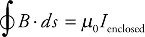
AP Physics C Exam
Part IV
Content Review for the AP Physics C Exam
Chapter 15
Electromagnetic Induction
INTRODUCTION
In Chapter 14, we learned that electric currents generate magnetic fields, and we will now see how magnetism can generate electric currents.
MOTIONAL EMF
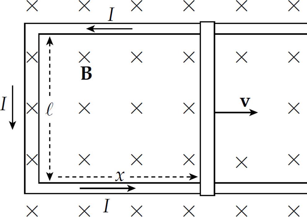
The figure below shows a conducting wire of length ℓ, moving with constant velocity v in the plane of the page through a uniform magnetic field B that’s perpendicular to the page. The magnetic field exerts a force on the moving conduction electrons in the wire. With B pointing into the page, the direction of v × B is upward, so the magnetic force, FB, on these electrons (which are negatively-charged) is downward.
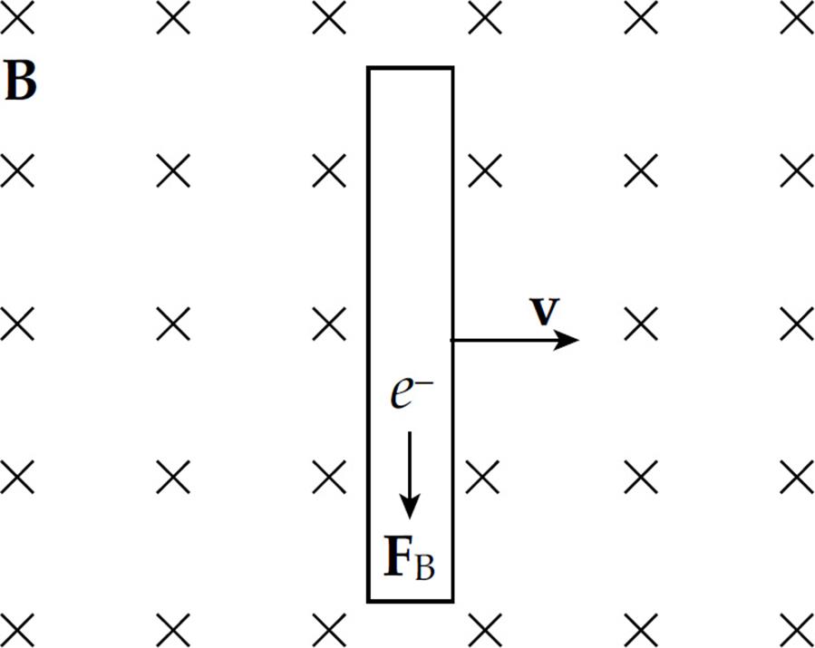
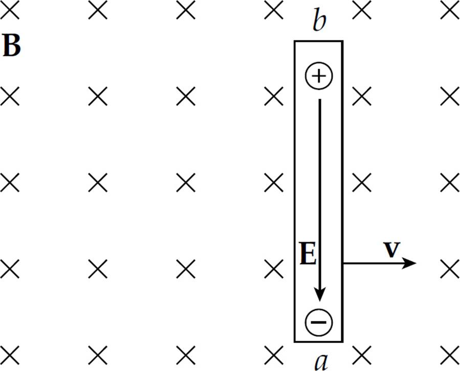
As a result, electrons will be pushed to the lower end of the wire, which will leave an excess of positive charge at its upper end. This separation of charge creates a uniform electric field, E, within the wire (pointing downward).
A charge q in the wire feels two forces: an electric force, FE = qE, and a magnetic force,
FB = q(v × B)
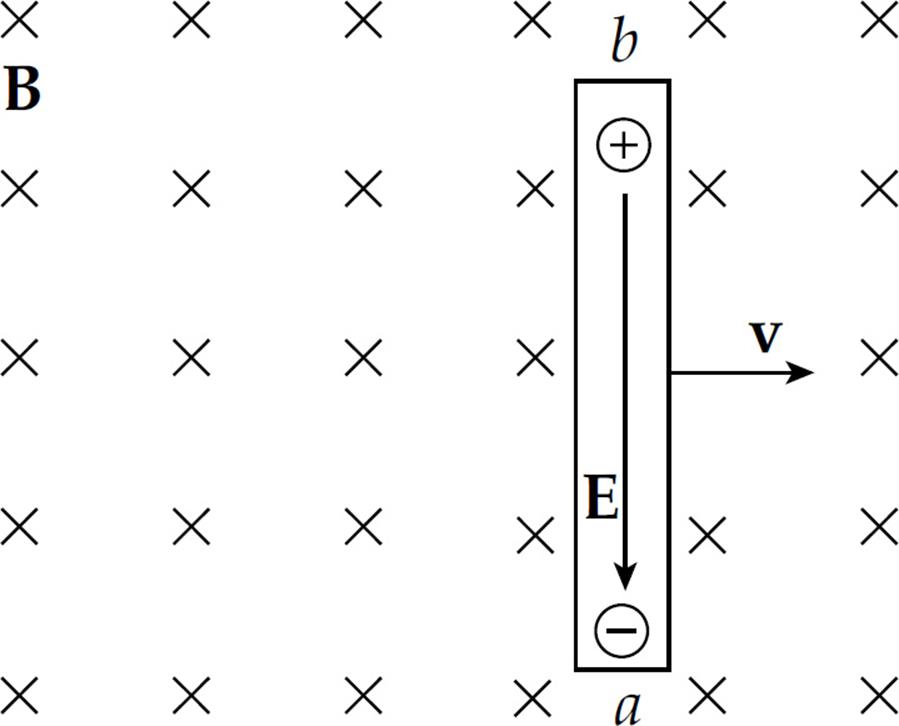
If q is negative, FE is upward and FB is downward; if q is positive, FE is downward and FB is upward. So, in both cases, the forces act in opposite directions. Once the magnitude of FE equals the magnitude of FB, the charges in the wire are in electromagnetic equilibrium. This occurs whenqE = qvB; that is, when E = vB.
The presence of the electric field creates a potential difference between the ends of the rod. Since negative charge accumulates at the lower end (which we’ll call point a) and positive charge accumulates at the upper end (point b), point b is at a higher electric potential.
The potential difference Vba is equal to Eℓ and, since E = vB, the potential difference can be written as vBℓ.
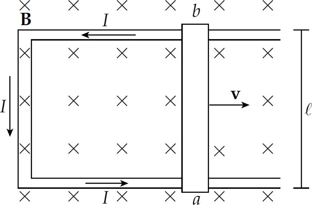
Now, imagine that the rod is sliding along a pair of conducting rails connected at the left by a stationary bar. The sliding rod now completes a rectangular circuit, and the potential difference Vba causes current to flow.
The motion of the sliding rod through the magnetic field creates an electromotive force, called motional emf:
ε = vBℓ
The existence of a current in the sliding rod causes the magnetic field to exert a force on it. Using the formula FB = I(ℓ × B), the fact that ℓ points upward (in the direction of the current) and B is into the page, tells us that the direction of FB on the rod is to the left. An external agent must provide this same amount of force to the right to maintain the rod’s constant velocity and keep the current flowing. The power that the external agent must supply is P = Fv = Iℓ Bv, and the electrical power delivered to the circuit is P = IVba = Iε = IvBℓ. Notice that these two expressions are identical. The energy provided by the external agent is transformed first into electrical energy and then thermal energy as the conductors making up the circuit dissipate heat.
FARADAY’S LAW OF ELECTROMAGNETIC INDUCTION
Electromotive force can be created by the motion of a conductor through a magnetic field, but there’s another way to create an emf from a magnetic field.
Magnetic Flux
Think back to Chapter 11 and electric flux. The electric flux through a surface of area A is equal to the product of A and the electric field that’s perpendicular to it. That is, ΦE = E⊥ A = E · A = EA cos θ. If E varies over the area A, then we write ΦE = ∫E · dA.
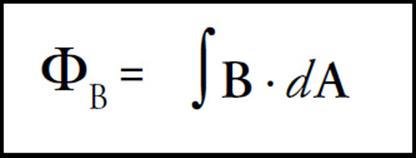
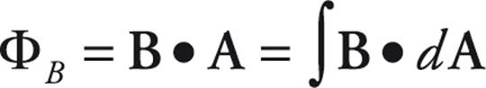
The idea of magnetic flux is exactly the same. The magnetic flux, ΦB, through an area A is equal to the product of A and the magnetic field perpendicular to it: ΦB = B⊥ A = B · A = BA cos θ. Again, if B varies over the area, then we must write:
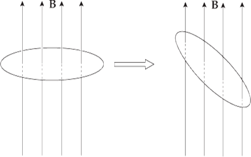
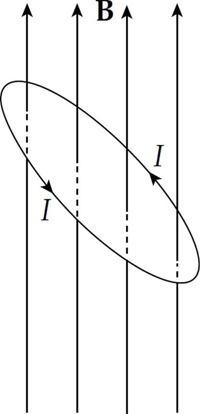
Example 1 The figure below shows two views of a circular loop of radius 3 cm placed within a uniform magnetic field, B (magnitude 0.2 T).
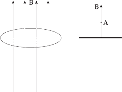
(a) What’s the magnetic flux through the loop?
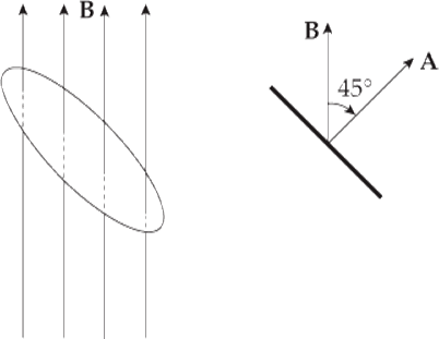
(b) What would be the magnetic flux through the loop if the loop were rotated 45°?
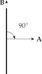
(c) What would be the magnetic flux through the loop if the loop were rotated 90°?
Solution.
(a) Since B is parallel to A, the magnetic flux is equal to BA:
ΦB = BA = B · πr2 = (0.2 T) · π(0.03 m)2 = 5.7 × 10⁻⁴ T·m2
The SI unit for magnetic flux, the tesla·meter2, is called a weber (abbreviated as Wb). So ΦB = 5.7 × 10⁻⁴ Wb.
(b) Since the angle between B and A is 45°, the magnetic flux through the loop is
ΦB = BA cos 45° = B · πr2 cos 45°= (0.2 T) · π(0.03 m)2 cos 45° = 4.0 × 10⁻⁴ Wb
(c) If the angle between B and A is 90°, the magnetic flux through the loop is zero, since cos 90° = 0.
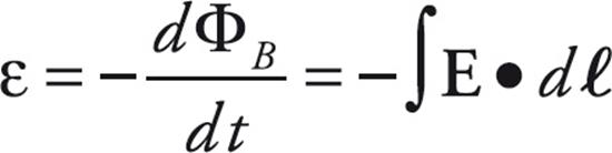
The concept of magnetic flux is crucial, because changes in magnetic flux induce emf. According to Faraday’s law of electromagnetic induction, the magnitude of the emf induced in a circuit is equal to the rate of change of the magnetic flux through the circuit. This can be written mathematically in the form
or, if we let  t → 0, we get
This induced emf can produce a current, which will then create its own magnetic field. The direction of the induced current is determined by the polarity of the induced emf and is given by Lenz’s law: The induced current will always flow in the direction that opposes the change in magnetic flux that produced it. If this were not so, then the magnetic flux created by the induced current would magnify the change that produced it, and energy would not be conserved. Lenz’s law can be included mathematically with Faraday’s law by the introduction of a minus sign; this leads to a single equation that expresses both results:
Example 2 The circular loop of Example 1 rotates at a constant angular speed through 45° in 0.5 s.
(a) What’s the induced emf in the loop?
(b) In which direction will current be induced to flow?
Solution.
(a) As we found in Example 1, the magnetic flux through the loop changes when the loop rotates. Using the values we determined earlier, Faraday’s law gives

(b) The original magnetic flux was 5.7 × 10⁻⁴ Wb upward, and was decreased to 4.0 × 10⁻⁴ Wb. So the change in magnetic flux is –1.7 × 10⁻⁴ Wb upward, or, equivalently,  ΦB = 1.7 × 10⁻⁴ Wb, downward. To oppose this change we would need to create some magnetic flux upward. The current would be induced in the counterclockwise direction (looking down on the loop), because the right-hand rule tells us that then the current would produce a magnetic field that would point up.
The current will flow only while the loop rotates, because emf is induced only when magnetic flux is changing. If the loop rotates 45° and then stops, the current will disappear.
Example 3 Again consider the conducting rod that’s moving with constant velocity v along a pair of parallel conducting rails (separated by a distance ℓ), within a uniform magnetic field, B:
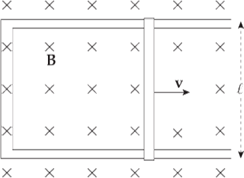
Find the induced emf and the direction of the induced current in the rectangular circuit.
Solution. The area of the rectangular loop is ℓx, where x is the distance from the left-hand bar to the moving rod:
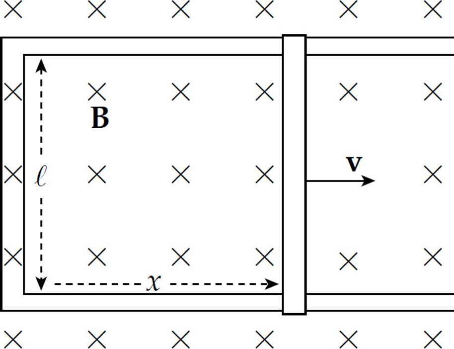
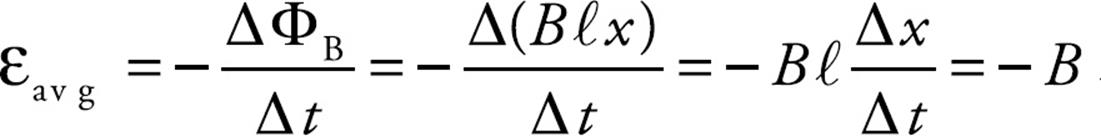
Because the area is changing, the magnetic flux through the loop is changing, which means that an emf will be induced in the loop. To calculate the induced emf, we first write ΦB = BA = Bℓx, then since x/t = v, we get
We can figure out the direction of the induced current from Lenz’s law. As the rod slides to the right, the magnetic flux into the page increases. How do we oppose an increasing into-the-page flux? By producing out-of-the-page flux. In order for the induced current to generate a magnetic field that points out of the plane of the page, the current must be directed counterclockwise (according to the right-hand rule).
Note that the magnitude of the induced emf and the direction of the current agree with the results we derived earlier, in the section on motional emf.
This example also shows how a violation of Lenz’s law would lead directly to a violation of the Law of Conservation of Energy. The current in the sliding rod is directed upward, as given by Lenz’s law, so the conduction electrons are drifting downward. The force on these drifting electrons—and thus, the rod itself—is directed to the left, opposing the force that’s pulling the rod to the right. If the current were directed downward, in violation of Lenz’s law, then the magnetic force on the rod would be to the right, causing the rod to accelerate to the right with ever-increasing speed and kinetic energy, without the input of an equal amount of energy from an external agent.
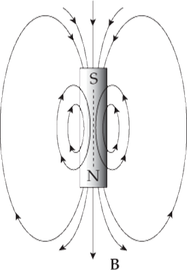
Example 4 A permanent magnet creates a magnetic field in the surrounding space. The end of the magnet at which the field lines emerge is designated the north pole (N), and the other end is the south pole (S):
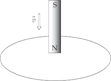
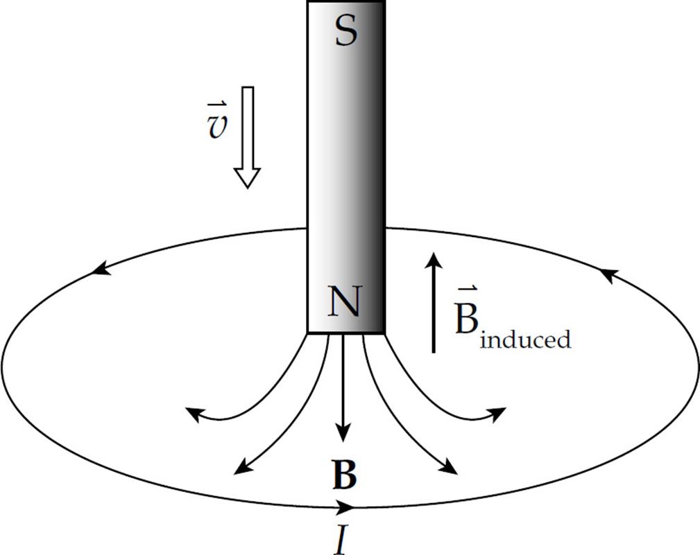
(a) The figure below shows a bar magnet moving down, through a circular loop of wire. What will be the direction of the induced current in the wire?
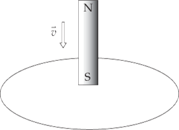
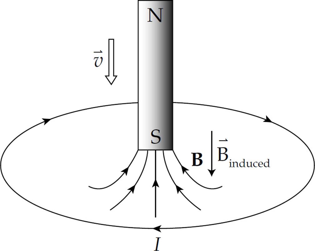
(b) What will be the direction of the induced current in the wire if the magnet is moved as shown in the following diagram?
Solution.
(a) The magnetic flux down, through the loop, increases as the magnet is moved. By Lenz’s law, the induced emf will generate a current that opposes this change. How do we oppose a change of more flux downward? By creating flux upward. So, according to the right-hand rule, the induced current must flow counterclockwise (because this current will generate an upward-pointing magnetic field, Binduced):
(b) In this case, the magnetic flux through the loop is upward and, as the south pole moves closer to the loop, the magnetic field strength increases so the magnetic flux through the loop increases upward. How do we oppose a change of more flux upward? By creating flux downward. Therefore, in accordance with the right-hand rule, the induced current will flow clockwise (because this current will generate a downward-pointing magnetic field):
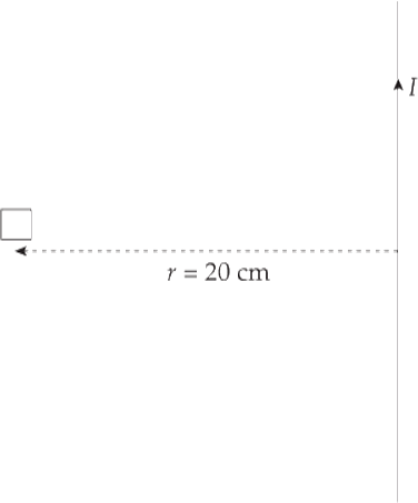
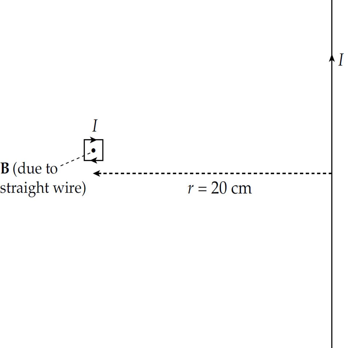
Example 5 A square loop of wire 2 cm on each side contains 5 tight turns and has a total resistance of 0.0002 Ω. It is placed 20 cm from a long, straight, current-carrying wire. If the current in the straight wire is increased at a steady rate from 20 A to 50 A in 2 s, determine the magnitude and direction of the current induced in the square loop. (Because the square loop is at such a great distance from the straight wire, assume that the magnetic field through the loop is uniform and equal to the magnetic field at its center.)
Solution. At the position of the square loop, the magnetic field due to the straight wire is directed out of the plane of the page and its strength is given by the equation B = (µ0/2π)(I/r). As the current in the straight wire increases, the magnetic flux through the turns of the square loop changes, inducing an emf and current. There are N = 5 turns; Faraday’s law becomes εavg = –N(ΦB/t), and

Substituting the given numerical values, we get
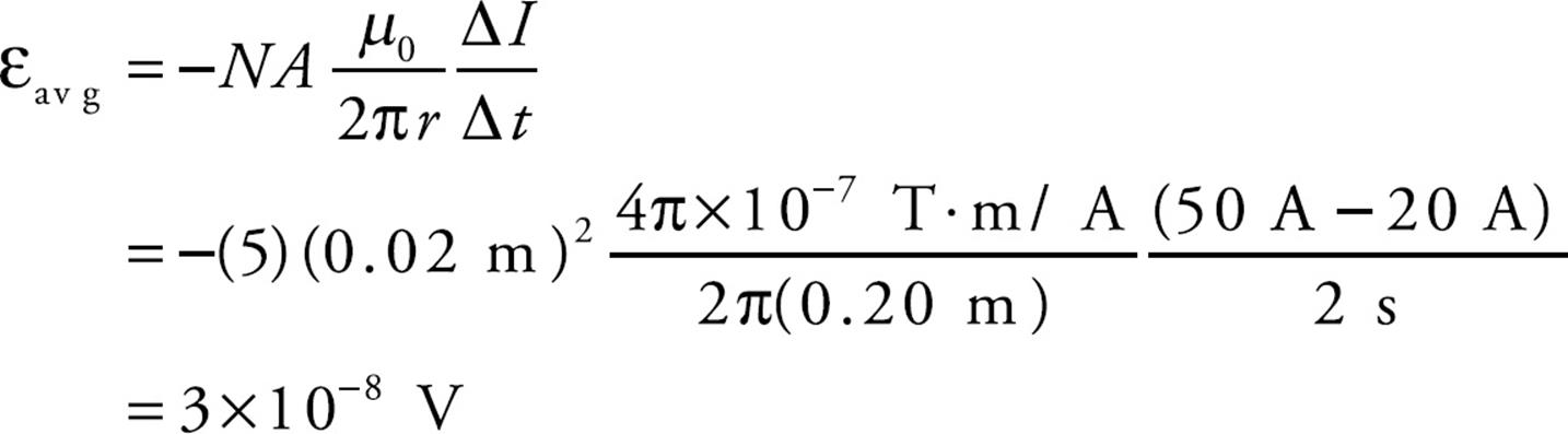
The magnetic flux through the loop is out of the page and increases as the current in the straight wire increases. To oppose an increasing out-of-the-page flux, the direction of the induced current should be clockwise, thereby generating an into-the-page magnetic field (and flux).
The value of the current in the loop will be
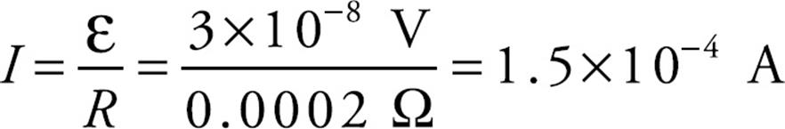
Example 6 A rectangular loop of wire 10 cm by 4 cm has a total resistance of 0.005 Ω. It is placed 2 cm from a long, straight, current-carrying wire. If the current in the straight wire is increased at a steady rate from 20 A to 50 A in 2 s, determine the direction of the current induced in the rectangular loop.
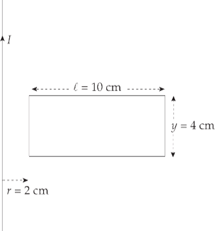
Solution. Unlike in the previous example, in this case the magnetic field varies greatly over the interior of the rectangular loop, so we have to use integration to calculate the magnetic flux. Take a narrow strip of width dx and height y, whose area is dA = y dx:
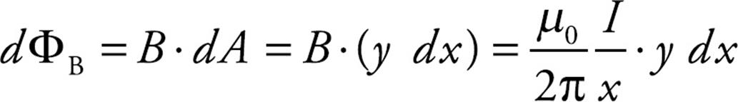
The magnetic field strength everywhere in this strip is B = (µ0/2π)(I/x), so the magnetic flux through the strip is
Integrating from x = r to x = r + ℓ gives the total magnetic flux through the loop.

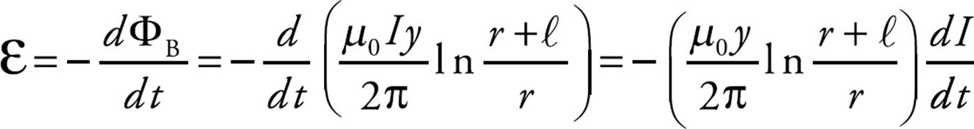
Faraday’s law then gives us
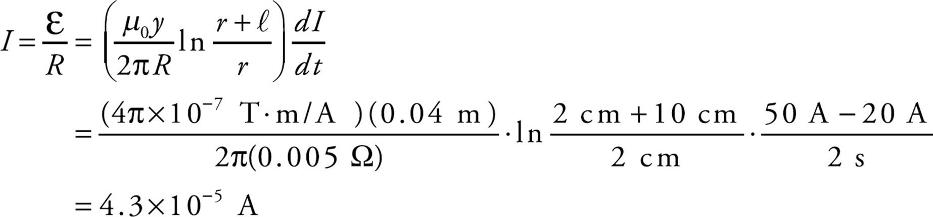
Ignoring the minus sign (which only reminds us that Lenz’s law has to be obeyed), the value of the current induced in the loop is
At the position of the rectangular loop, the magnetic field due to the straight wire is directed into the plane of the page. So, the magnetic flux through the loop is into the page and increases as the current in the straight wire increases. To oppose an increasing into-the-page flux, the direction of the induced current will be counterclockwise, generating an out-of-the-page magnetic field (and flux).
Induced Electric Fields
In Examples 4, 5, and 6, an electric current was induced in a stationary conducting loop by a changing magnetic flux through the loop, but what was the source of the force that pushed these charges around the loop? It was not the magnetic force, because the loop was stationary. It must therefore have been an electric force that was produced by an electric field. The changing magnetic field produced the electric field, which acted on the free charges in the conducting loop and caused the current.
Let’s look at a specific situation. The figure below is a view down the central axis of an ideal solenoid (ideal means that the magnetic field is uniform and parallel to the axis and that no magnetic field exists outside). Surrounding the solenoid is a loop of wire.
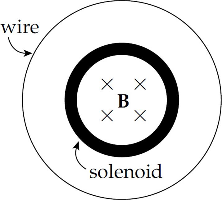
Now suppose that the current in the solenoid is increased, which increases the strength of its magnetic field. This changes the magnetic flux through the wire and induces a current (which is directed counterclockwise). The force that pushes the charges around this wire is FE = qE; E is the induced electric field.
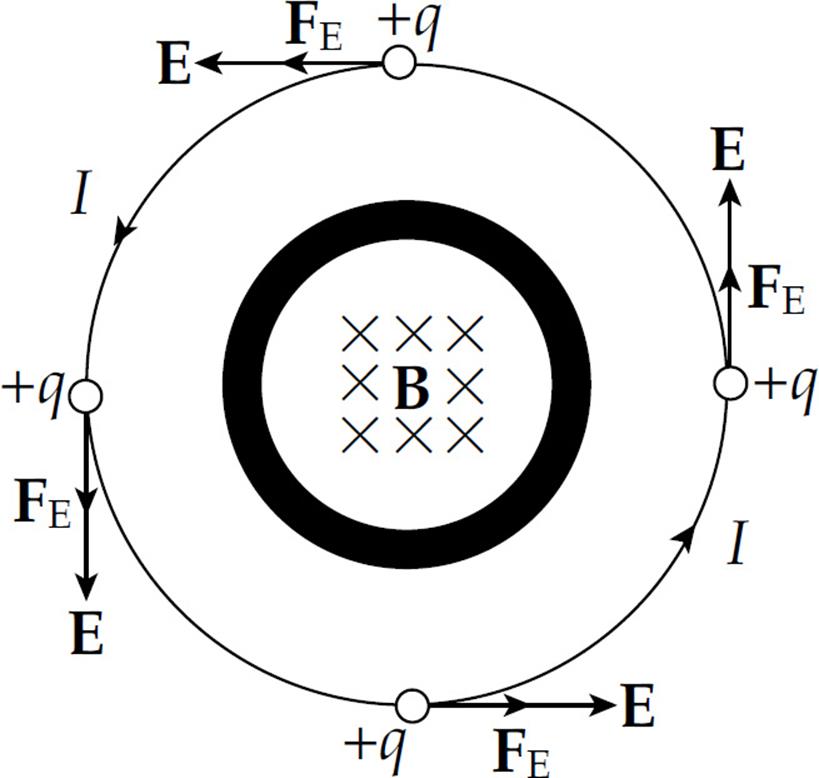
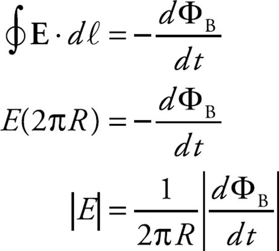
The work done on a charge q as it makes one revolution is FE times the distance around the wire, FE · 2πr = qE·(2πr). So the work per unit charge, which is the definition of emf, is equal to E(2πr). But Faraday’s law says that the emf is equal to –dΦB/dt.
E(2πr) = –dΦB/dt
This equation can be generalized by saying that the work done per unit charge by the induced electric field around a closed path is equal to  . Therefore,
This is a restatement of Faraday’s law that includes the electric field, E, induced by the changing magnetic flux. Notice that this electric field is different from the ones we studied in the previous chapters. Electric fields created by stationary source charges, called electrostatic fields, are conservative, meaning that the work done by them on charges moved along closed paths is always zero. However, as we’ve just seen in the example of the solenoid above, the electric field induced by a changing magnetic flux does not share this property. The work done by Einduced on a charge as it moves around a closed path is equal to  , which is not zero because dΦB/dt is not zero. Because of this, the electric field induced by a changing magnetic flux is nonconservative.
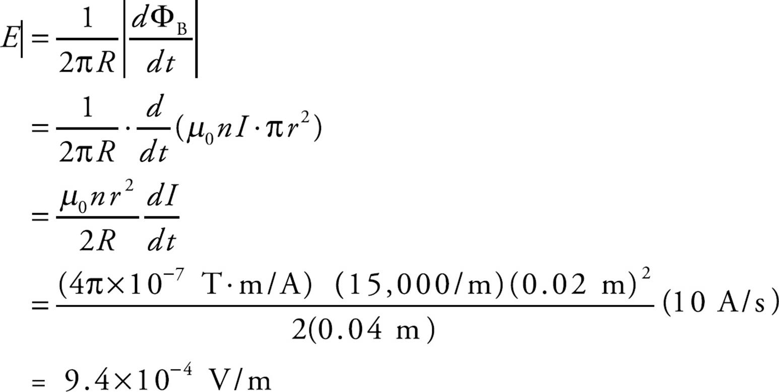
Example 7 For the situation just described, assume that the solenoid has 15,000 turns per meter and a radius of r = 2 cm. The radius of the circular loop is R = 4 cm. If the current in the solenoid is increased at a rate of 10 A/s, what is the magnitude of the induced electric field at each position along the circular wire?
Solution. From Faraday’s law, we have
Assuming that the magnetic field exists only inside the solenoid, the magnetic flux through the circular wire is BA = B(πr2), where B = µ0nI:
ΦB = (µ0nI) · (πr2)
Therefore,
INDUCTANCE
Placing a capacitor in series with a resistor and battery in an electric circuit causes the current to drop exponentially from ε/R (when the switch is closed) to zero, as charge builds up on the capacitor and causes the voltage across the capacitor to oppose the emf of the battery. A similar thing happens when an inductor is placed in series with a resistor and a source of emf in an electric circuit.
An inductor is a circuit element that opposes changes in current. The prototypical inductor is a coil (a solenoid) that looks like this in diagrams:
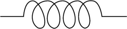
How does this coil oppose changes in current in a circuit? Well, when current exists in the coil, a magnetic field is created, and magnetic flux passes through the loops. If the current changes, then the magnetic field changes proportionately, as does the magnetic flux through the loops. But, according to Faraday’s law of induction, a changing magnetic flux induces an emf that opposes the change that produced it. In other words, the changing magnetic flux through the coil, due to the current in the coil itself, produces a self-induced emf. Since this self-induced emf opposes the change in the current that produced it, it’s also called back emf.
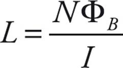
Assume that the inductor contains N turns and that ΦB is the magnetic flux through each turn. Then the total magnetic flux through the entire coil is NΦB; this is proportional to the current, so NΦB = LI for some constant, L. The proportionality constant L is called the inductance (or self-inductance) of the coil:
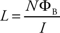
The SI unit for inductance is the weber per ampere, which is renamed a henry (H).
Example 8 An ideal solenoid of cross-sectional area A and length ℓ contains n turns per unit length. What is its self-inductance?
Solution. The magnetic field inside an ideal solenoid is parallel to its central axis and has strength B = µ0nI. Since the solenoid’s length is ℓ, the total number of turns, N, is nℓ. Therefore,

Or, in terms of the total number of turns in the solenoid, L = µ0N2A/ℓ.
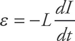
The self-induced emf in an inductor now follows directly from the definition of L and Faraday’s law. Since N ΦB = LI, we have N(d ΦB/dt) = L(dI/dt). But by Faraday’s law, ε = –N(d ΦB/dt). So,
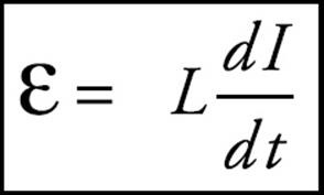
The self-induced emf is proportional to the rate of change of the current. The faster the current tries to change, the greater is the self-induced (back) emf. But if the current is steady, then ε = 0.
RL Circuits
Consider the following circuit, which contains a battery, an inductor, and a resistor:
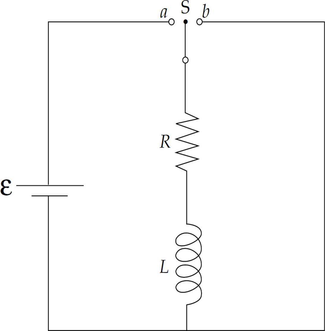
At time t = 0, the switch is moved to point a. Applying Kirchhoff’s loop rule to the left-hand part of the circuit, we obtain
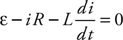
where R is the resistance and L is the inductance. We apply the method of separation of variables to solve the current in the circuit as a function of time. First we rearrange the equation so that one variable is on the left side of the equation, and the other variable is on the right side.
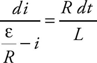
We then integrate both sides of the equation:
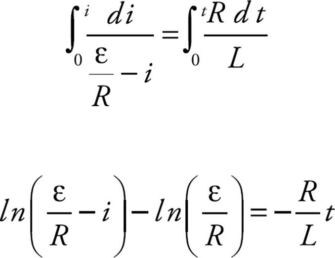
A little algebraic manipulation allows us to solve for the current as a function of time, i(t):
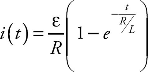
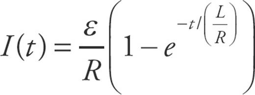
The ratio of L to R (in the exponent) is called the inductive time constant: τL = L/R, and the equation for the rising current in the RL circuit (a circuit that contains a resistor and an inductor) can be written as:
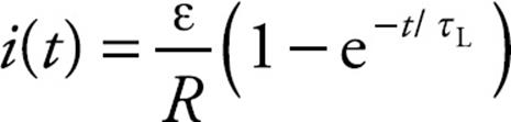
which is similar to the equation for the gradually rising charge on the plates of a capacitor in an RC circuit. Notice that for an RL circuit the current increases over time and for an RC circuit the current decreases over time.
As current builds in the circuit, the source of emf provides electrical energy. Some of this energy is dissipated as heat by the resistor, and the remainder is stored in the magnetic field of the inductor.
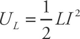
The amount of stored energy is
where L is the inductance of the inductor carrying a current I.
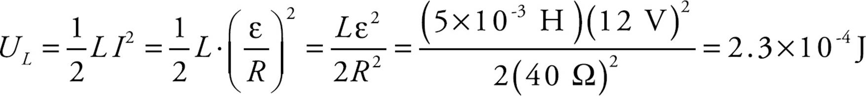
Example 9 In a particular circuit, assume that ε = 12V, R = 40 Ω, and L = 5 mH. How much energy is stored in the inductor’s magnetic field when the current reaches its maximum steady-state value?
Solution. When the current in the circuit reaches its maximum steady-state value, I = ε/R. At this point, the energy stored in the magnetic field of the inductor is
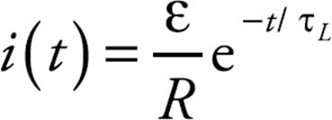
Once the current has reached its steady-state value of ε/R, imagine that you move the switch to point b. Without the inductor, the current would drop abruptly to zero (because the source of emf has been taken out of the circuit). But the inductor would oppose this abrupt decrease in the current by producing a self-induced emf. The presence of this emf would cause the current to die out gradually, according to the equation
Example 10
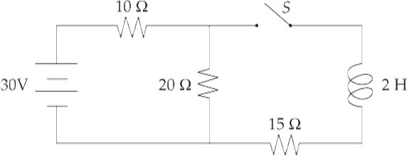
A circuit is connected as shown above.
(a) Determine the current through the 10 Ω resistor when the switch is open.
(b) Determine the current through the 15 Ω resistor when the switch is first closed.
(c) Determine the current through the 10 Ω resistor when the switch has been closed a long time.
Solution.
(a) When the switch is open the circuit is a basic series circuit with a total resistance of 30 Ω. Use Ohm’s law to solve for the current:
V = IR ⇒ 30 = I(30) ⇒ I = 1 A
(b) When the switch is first closed the inductor will not let the current go through that part of the branch because it opposes changes in current. Therefore the current through the 15 Ω resistor is zero. (The current is 1A in the rest of the circuit.)
(c) After the switch has been closed a long time the inductor acts like a wire because the current is constant. Now we solve for the resistance of the parallel part of the circuit. 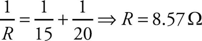
Then the total resistance is that value added to 10 Ω · Rtot = 18.57 Ω
The current leaving the battery will be the current through the 10 Ω resistor. Solve for that current using Ohm’s law.
V = IR ⇒ 30 = I(18.57) ⇒ I = 1.62 A
LC Circuits
The RC circuit we looked at in Chapter 13 and the RL circuit that we just studied are similar in that they both experience an exponential increase or decrease of current. However, an LC circuit, which is a circuit that contains both an inductor and a capacitor, behaves quite differently.
The following figure shows a capacitor and an inductor in a simple series circuit.
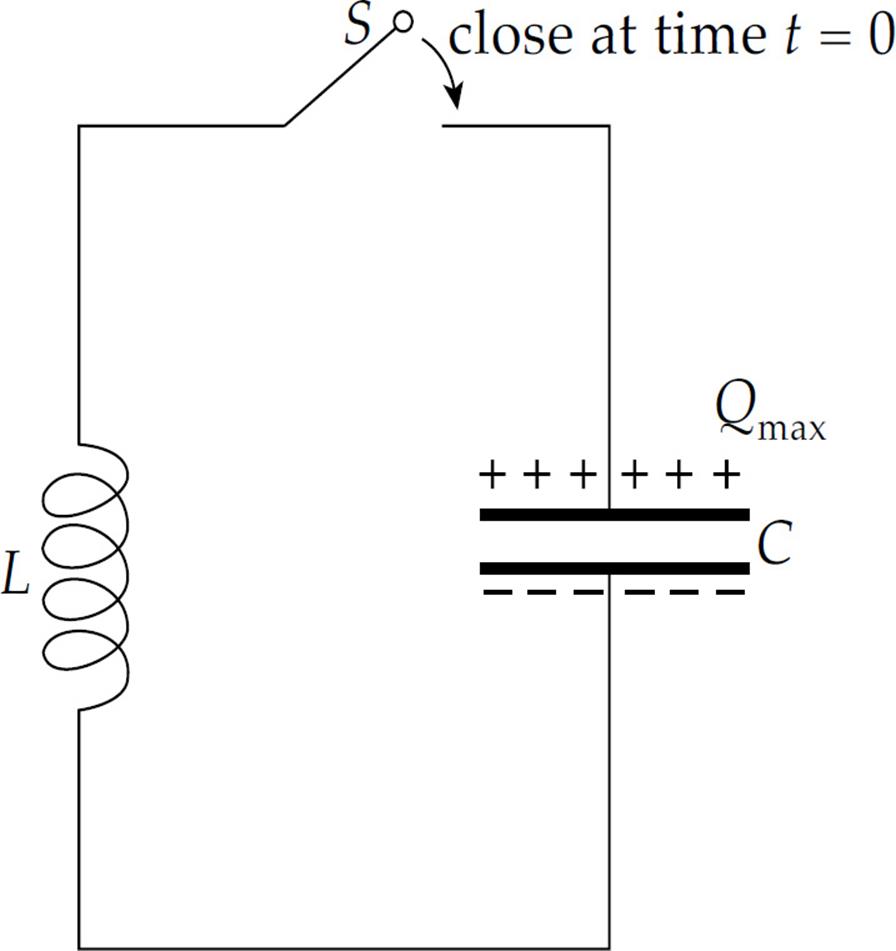
Let’s assume that initially there is no current and that the capacitor is charged; at time t = 0, the switch S is closed and the circuit is complete. The presence of the inductor prevents the capacitor from discharging abruptly, so the current rises gradually and the energy in the electric field of the capacitor is transferred to energy in the magnetic field of the inductor. Once the capacitor has discharged, all the energy is in the inductor’s magnetic field. The current in the inductor (now at its maximum), delivers charge to the capacitor, but in the opposite direction from its original charge configuration. The current gradually returns to zero as the magnetic-field energy in the inductor is transformed back to electric-field energy in the capacitor.
The capacitor starts to discharge again, but this time it sends current in the opposite direction. The current rises gradually, reaching a maximum value as the charge on the capacitor reaches zero. The inductor continues to deliver charge to the capacitor as the current gradually returns to zero, and it finds itself right back where it started. The circuit oscillates, and this defines one cycle of oscillation.
Applying Kirchhoff’s loop equation to this circuit we obtain
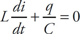
The current is the derivative as a function of time, so this equation can be rewritten as
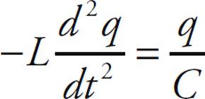
This can be rewritten as
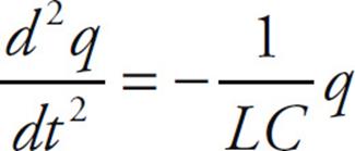
This is a second-order linear differential equation of the same form we studied in Chapter 10, when we studied oscillations. In this case, the equation above is in the same form as that for a mass oscillating on the end of a spring,
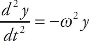
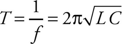
Thus, we can infer that in the case of an inductor and capacitor in a circuit, 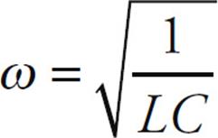 . The angular frequency, ω, is related to the frequency of oscillation according to ω = 2πf.
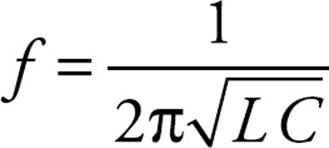
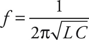
The frequency of oscillation is related to inductance and capacitance by the equation
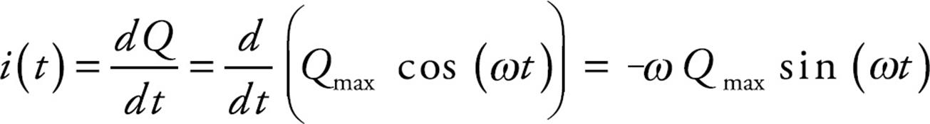
The charge on the capacitor, as a function of time (assuming that it possessed its maximum charge, Qmax, at time t = 0) is
Q(t) = Qmax cos (ωt)
where ω = 2πf.
Example 11 Find an equation for the current in the LC circuit as a function of time. How long does it take for the circuit to complete a full oscillation?
Solution. By definition, the current is the time derivative of the charge. So,
The time required to complete a cycle (the period) would be the reciprocal of the frequency:
MAXWELL’S EQUATIONS
We’ll finish up this chapter with a set of four equations that embody the subject of electromagnetism.
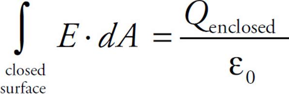
1. Gauss’s Law
This law, first studied in Chapter 11, gives us a method for calculating electric fields and is particularly useful when the system we’re working with possesses symmetry.
2. Gauss’s Law for Magnetic Fields
We mentioned earlier that magnetic field lines always form closed loops that encircle the current that generates them. (Remember: This property is not shared by electrostatic fields, which radiate away from positive source charges and toward negative ones.) The fact that magnetic field lines always close upon themselves tells us that the magnetic flux through any closed surface must be zero; as much magnetic flux will enter the closed surface as will exit it. Mathematically, this says:
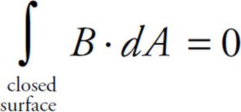
Another statement of this law is that there are no magnetic monopoles. If there were, a single isolated magnetic north pole would generate a magnetic field that radiates away, and an isolated magnetic south pole would generate a magnetic field that radiates inward, toward the pole. A closed surface surrounding such a magnetic charge (if one existed) would have a nonzero flux through it. No magnetic monopoles like this have ever been observed.
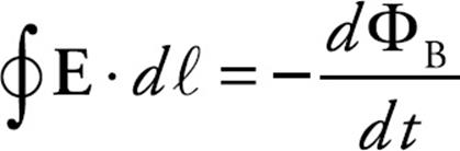
3. Faraday’s Law
As we discussed in this chapter, a changing magnetic flux induces an emf; this also means that a changing magnetic field produces an electric field. The equation is
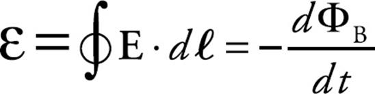
This equation is typically used to find the emf and the electric field induced by a changing magnetic flux.
4. The Ampere-Maxwell Law
The final equation in this set begins with Ampere’s law, which provides us with a method for calculating magnetic fields and is particularly useful when systems are symmetrical. It reads
You may notice that the first two equations listed in this section possess a sort of symmetry; there’s a Gauss’s law for E-fields and one for B-fields. The third equation says that a changing B-field produces an E-field. One question we haven’t asked yet, which is of interest here is, Does a changing E-field produce a B-field? The answer is “yes,” and the equation can be amended in the following way [Maxwell added the missing piece, which is proportional to the rate of change of the electric flux, µ0ε0(d ΦE/dt)]:
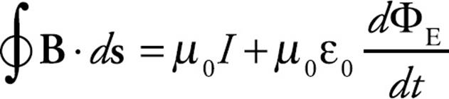
This shows that a changing electric field, which appears on the right-hand side of the equation [in the term µ0ε0(d ΦE/dt)], will produce a magnetic field, which appears on the left-hand side of the equation.
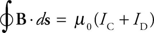
The quantity ε0(d ΦE/dt) has units of current and is called displacement current, ID. It differs from the current I, which is conduction current (IC), because while IC is composed of moving electric charge, ID is not. The Ampere–Maxwell equation can be written in terms of conduction current and displacement current as follows:
CHAPTER 15 REVIEW QUESTIONS
The answers and explanations can be found in Chapter 16.
Section I: Multiple Choice
1. A metal rod of length L is pulled upward with constant velocity v through a uniform magnetic field B that points out of the plane of the page.
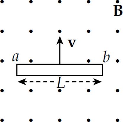
What is the potential difference between points a and b?
(A) 0
(B) ![]() v BL, with point a at the higher potential
v BL, with point a at the higher potential
(C) ![]() v BL, with point b at the higher potential
v BL, with point b at the higher potential
(D) vBL, with point a at the higher potential
(E) vBL, with point b at the higher potential
2. A circular disk of radius a is rotating at a constant angular speed ω in a uniform magnetic field, B, which is directed out of the plane of the page.
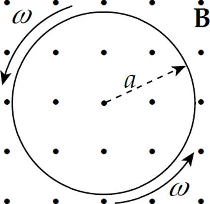
Determine the induced emf between the center of the disk and the rim.
(A) ![]() ωBa
ωBa
(B) ![]() Ba
Ba
(C) ![]() ωBa2
ωBa2
(D) ωBa2
(E) 2πωBa2
3. A conducting rod of length 0.2 m and resistance 10 ohms between its endpoints slides without friction along a U-shaped conductor in a uniform magnetic field B of magnitude 0.5 T perpendicular to the plane of the conductor, as shown in the diagram below.
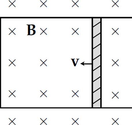
If the rod is moving with velocity v = 3 m/s to the left, what is the magnitude and direction of the current induced in the rod?
|
Current |
Direction |
|
|
(A) |
0.03 A |
down |
|
(B) |
0.03 A |
up |
|
(C) |
0.3 A |
down |
|
(D) |
0.3 A |
up |
|
(E) |
3 A |
down |
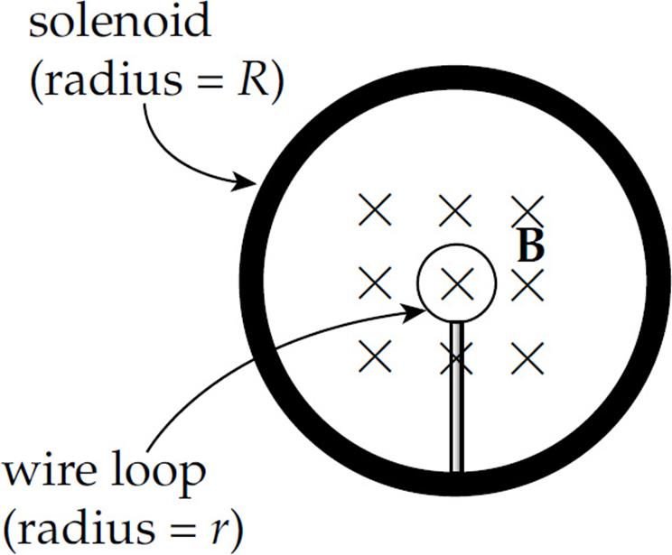
4. In the figure below, a small, circular loop of wire (radius r) is placed on an insulating stand inside a hollow solenoid of radius R. The solenoid has n turns per unit length and carries a current I. If the current in the solenoid is decreased at a steady rate of a amps/s, determine the induced emf, ε, and the direction of the induced current in the loop.
(A) ε = μ0πnr2a; induced current is clockwise
(B) ε = μ0πnr2a; induced current is couterclockwise
(C) ε = μ0πnR2a; induced current is clockwise
(D) ε = μ0πnR2a; induced current is couterclockwise
(E) ε = μ0πInR2a; induced current is counterclockwise
5. In the figure below, a permanent bar magnet is pulled upward with a constant velocity through a loop of wire.
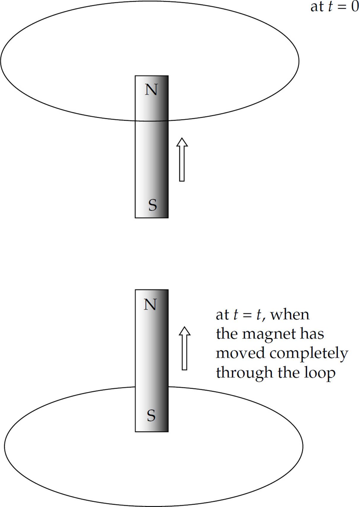
Which of the following best describes the direction(s) of the current induced in the loop (looking down on the loop from above)?
(A) Always clockwise
(B) Always counterclockwise
(C) First clockwise, then counterclockwise
(D) First counterclockwise, then clockwise
(E) No current will be induced in the loop
6. A square loop of wire (side length = s) surrounds a long, straight wire such that the wire passes through the center of the square.
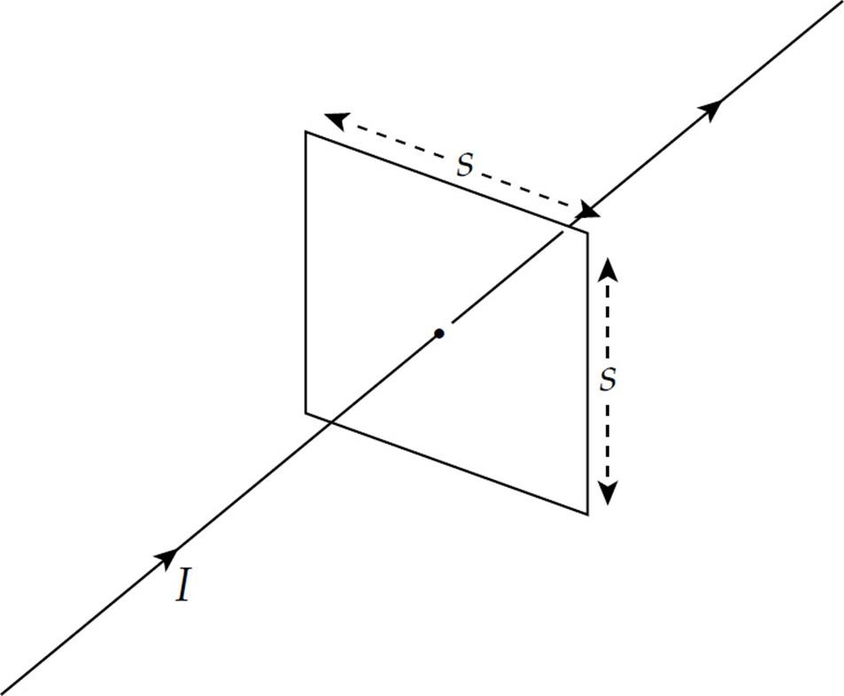
If the current in the wire is I, determine the current induced in the square loop.
(A) 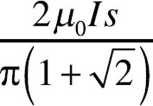
(B) 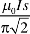
(C) 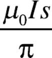
(D) 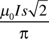
(E) 0
Questions 7–9
A circuit contains a solenoid of inductance L in series with a resistor of resistance R and a battery with terminal voltage ε. At time t = 0, a switch is closed and the circuit is completed.
7. How long does it take for the current to reach 3/4 of its maximum (steady-state) value?
(A) (ln 4)(L/R)
(B) (ln ![]() )(L/R)
)(L/R)
(C) (ln ![]() )(L/R)
)(L/R)
(D) (ln ![]() )(R/L)
)(R/L)
(E) (ln 4)(R/L)
8. When the current reaches its maximum value, how much energy is stored in the magnetic field of th solenoid?
(A) L2ε2/(4R2)
(B) L2ε2/(2R2)
(C) Lε2/(4R2)
(D) Lε2/(2R2)
(E) 0
9. When the current reaches its maximum value, what is the total magnetic flux through the solenoid?
(A) Lε
(B) Lε/R
(C) ε/(RL)
(D) RL/ε
(E) 0
10. Which one of Maxwell’s equations states that a changing electric field produces a magnetic field?
(A) Gauss’s law
(B) Gauss’s law for magnetism
(C) Biot-Savart law
(D) Ampere-Maxwell law
(E) Faraday’s law
Section II: Free Response
1. The diagram below shows two views of a metal rod of length ℓ rotating with constant angular speed ω about an axis that is in the plane of the page. The rotation takes place in a uniform magnetic field B whose direction is parallel to the angular velocity ω.
(a) What is the emf induced between the ends of the rod?
(b) What is the polarity (+ or –) of the rotating end?
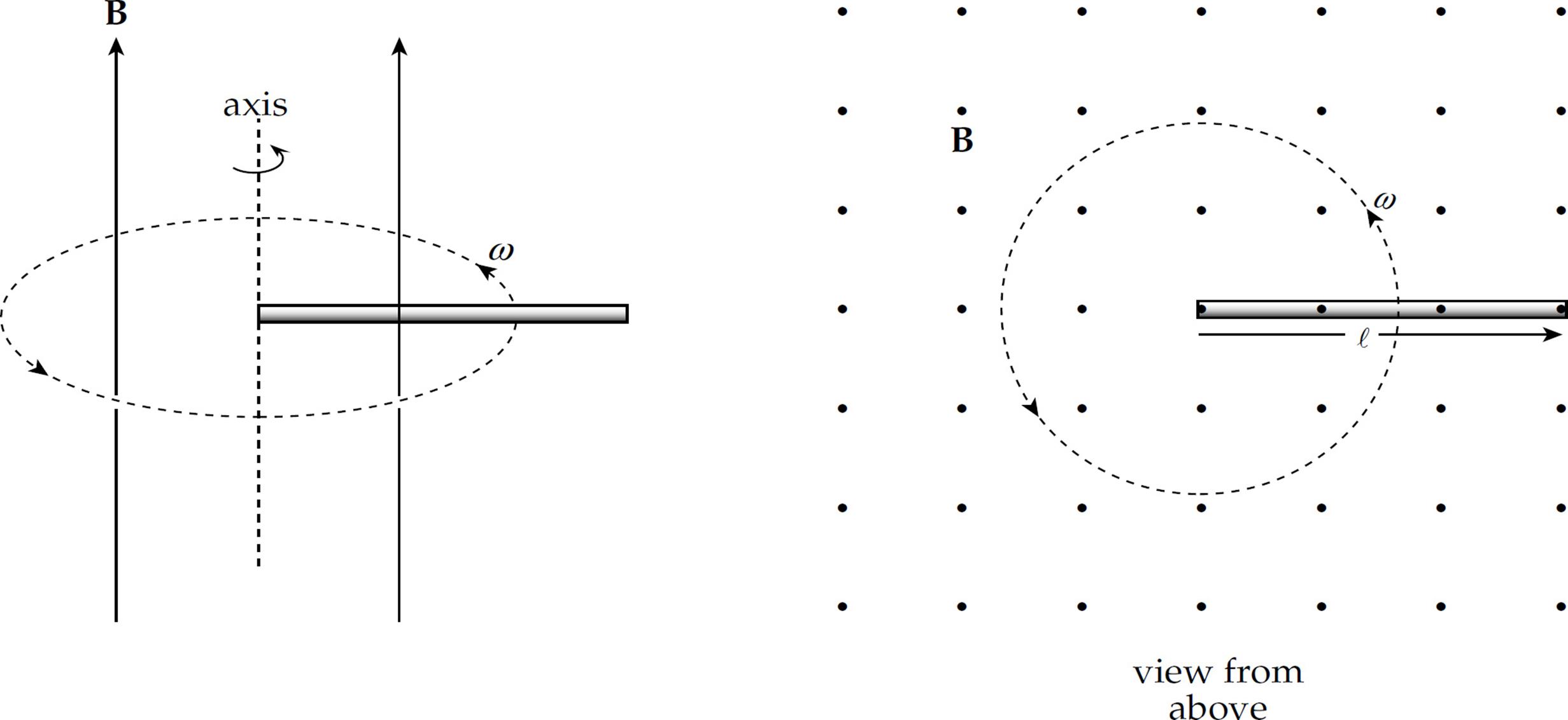
In the following diagram, a metal rod of length ℓ moves with constant velocity v parallel to a long, straight wire carrying a steady current I. The lower end of the rod maintains a distance of a from the straight wire.
(c) What is the emf induced between the ends of the rod?
(d) What is the polarity (+ or –) of the end that is farther from the straight wire?
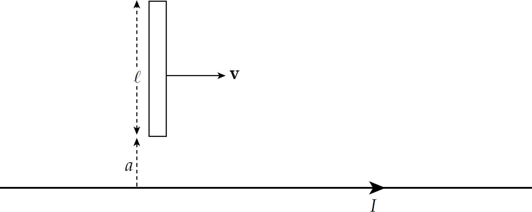
2. A rectangular loop of wire (side lengths a and b) rotates with constant angular speed ω in a uniform magnetic field B. At time t = 0, the plane of the loop is perpendicular to B, as shown in the figure on the left. The magnetic field B is directed to the right (in the +x direction), and the rotation axis is the y-axis (with ωin the +ydirection), and the four corners of the loop are labeled 1, 2, 3, and 4. (Express answers in terms of a, b, ω, B, and fundamental constants.)
(a) Find a formula that gives the magnetic flux ΦB through the loop as a function of time, t.
(b) Find a formula that gives the emf induced in the loop as a function of time, t.
(c) If the total resistance of the loop is R, what is the current induced in the loop?
(d) When ωt = π/2, is the induced current in the loop directed from Point 1 to Point 2 (–y direction) or from Point 2 to Point 1 (+y direction)?
(e) Find the rate at which energy is dissipated (as joule heat) in the wires that comprise the loop, and the amount of energy dissipated per revolution.
(f) Find the external torque required to keep the loop rotating at the constant angular speed ω.
3. The figure below shows a toroidal solenoid of mean radius R and N total windings. The cross-sections of the toroid are circles of radius a (which is much smaller than R, so variations in the magnetic field strength within the space enclosed by the windings may be neglected).
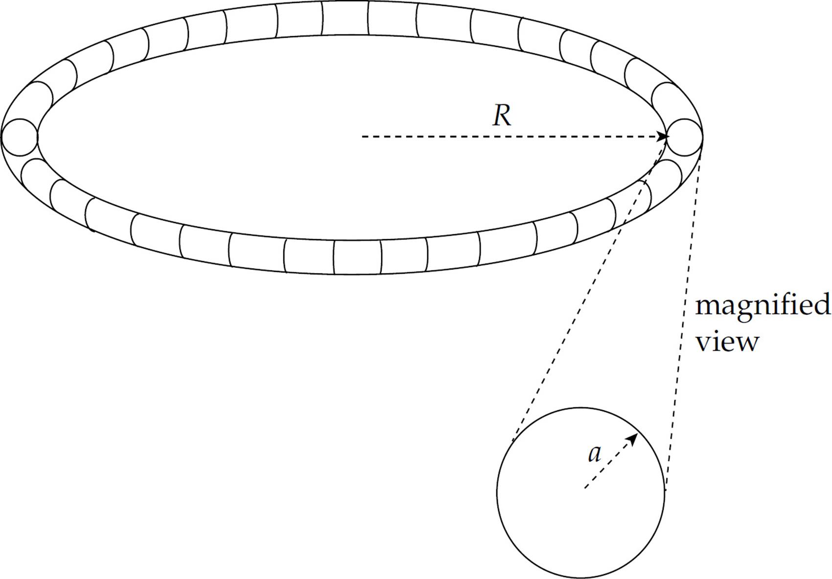
(a) Use Ampere’s law to find the magnetic field strength within the toroid. Write your answer in terms of N, I, R, and fundamental constants.
A circular loop of wire of radius 2a is placed around the toroid as shown:
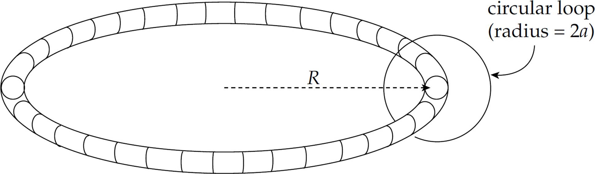
Assume that the current in the toroid is varied sinusoidally according to the equation I(t) = I0 sin ωt, where I0 and ω are fixed constants.
(b) Determine the emf induced in the circular wire loop.
(c) Determine the electric field induced at the position of the circular wire loop.
(d) What is the self-inductance of the toroidal solenoid?
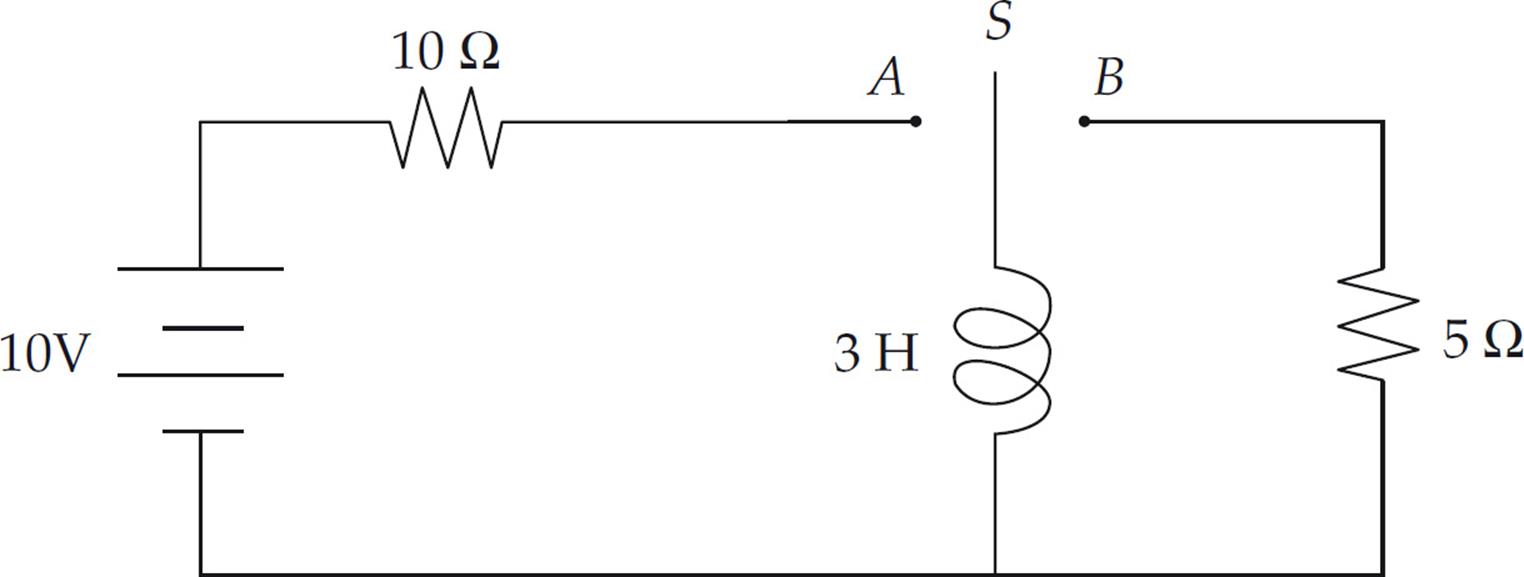
4. A circuit is connected as shown above. The switch S is initially open. Then it is moved to position A.
(a) Determine the current in the circuit immediately after the switch is closed.
(b) Determine the current in the circuit a long time after the switch is closed.
Some time after the steady state situation has been reached, the switch is moved almost instantaneously from position A to position B.
(c) Determine the current through the 5 Ω resistor immediately after the switch has been moved.
(d) Determine the potential difference across the inductor immediately after the switch has been closed.
Summary
Motional Emf
- A conducting bar with a component of its velocity perpendicular to the magnetic field will have an induced emf across its length. This is due to the fact that each charge in the bar will have a force on it and the charges will separate until the magnetic force and the electric force caused by the attraction of the separate charges are equal. The motional emf is given by the equation ε = Bℓv.
Magnetic Flux, Faraday’s Law, and Lenz’s Law
- Magnetic flux is determined by the number of magnetic field lines that pass through a surface. It is given by the dot product of the magnetic field and area vector:
- When the magnetic flux is changing, an emf is induced in a conductor. This is known as Faraday’s Law of Electromagnetic Induction. The general form of Faraday’s Law is
- The first part of the equation is used to calculate the induced emf from a changing magnetic flux and the last part can be used to calculate the induced electric field created in the conductor. The last part of the equation comes from
 , where the potential difference is replaced with the emf.
 - Lenz’s Law is used to determine the direction of the induced current and explains the negative sign in Faraday’s Law. The induced current will flow in the direction that opposes the change in the magnetic flux that produced it.
Inductance
- An inductor is an electric device that has a self-induced emf that opposes the change in the current in the circuit. The inductance, L, is given by the equation
 .
. - The emf of an inductor is
 , where the negative sign indicates the emf is opposing the change in the current through the circuit.
 - The energy stored in the magnetic field on an inductor is
 .
.
Resistor-Inductor (RL) Circuits
- When a switch is closed in a typical RL circuit, the current increases exponentially over time. This is due to the fact that the inductor opposes the change in the current so will not let it increase from zero to a maximum instantaneously. The equation for the current is
 , where the time constant is now given by
  .
.
Inductor-Capacitor (LC) Circuits
- When a switch is closed in a typical LC circuit the energy oscillates between being stored in the electric field of the capacitor and the magnetic field of the inductor. The frequency of the oscillation is
 and the charge of the plate is given by
  .
.