AP Physics C Exam
Part IV
Content Review for the AP Physics C Exam
Chapter 16
Solutions to the Chapter Review Questions
CHAPTER 4 REVIEW QUESTIONS
Section I: Multiple Choice
1. A Traveling once around a circular path means that the final position is the same as the initial position. Therefore, the displacement is zero. The average speed, which is total distance traveled divided by elapsed time, cannot be zero. Since the velocity changed (because its direction changed), there was a nonzero acceleration. Therefore, only Statement I is true.
2. C By definition ā =  v /
v /  t. We determine
  v = v2 – v1 = v2 + (–v1) geometrically as follows:
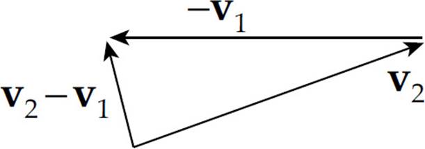
Since t is a positive scalar, the direction of ā is the same as the direction of v, which is displayed above; choice (C) is best.
3. C Statement I is false since a projectile experiencing only the constant acceleration due to gravity can travel in a parabolic trajectory. Statement II is true: Zero acceleration means no change in speed (or direction). Statement III is false: An object whose speed remains constant but whose velocity vector is changing direction is accelerating.
4. C The baseball is still under the influence of Earth’s gravity. Its acceleration throughout the entire flight is constant, equal to g downward.
5. A Use Big Five #3 with v0 = 0:
6. D Use Big Five #5 with v0 = 0 (calling down the positive direction):

7. C Apply Big Five #3 to the vertical motion, calling down the positive direction:

Note that the stone’s initial horizontal speed (v0x = 10 m/s) is irrelevant.
8. B First we determine the time required for the ball to reach the top of its parabolic trajectory (which is the time required for the vertical velocity to drop to zero).
The total flight time is equal to twice this value:
9. C After 4 seconds, the stone’s vertical speed has changed by vy = ayt = (10 m/s2)(4 s) = 40 m/s. Since v0y = 0, the value of vy at t = 4 is 40 m/s. The horizontal speed does not change. Therefore, when the rock hits the water, its velocity has a horizontal component of 30 m/s and a vertical component of 40 m/s.
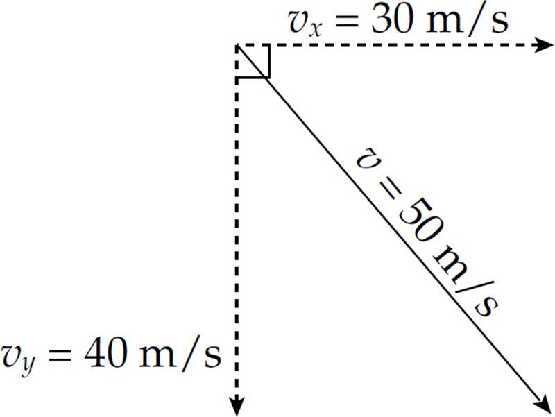
By the Pythagorean theorem, the magnitude of the total velocity, v, is 50 m/s.
10. E Since the acceleration of the projectile is always downward (because it’s gravitational acceleration), the vertical speed decreases as the projectile rises and increases as the projectile falls. Statements (A), (B), (C), and (D) are all false.
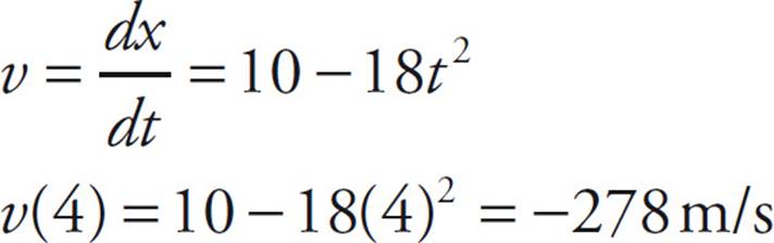
11. D The velocity is the derivative of the position function. Take the derivative of x(t) and plug in t = 4 s, to determine the velocity.
12. D The displacement of the object is the area between the velocity function and the t-axis. Divide the area up to 3 seconds into one rectangle created for the first second and one triangle for the next two seconds.
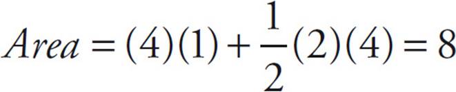
Remember that the area is the displacement, not the position. Since the object started at x = 3 m, when t = 0 s, it is now 8 meters away from that point. Therefore its position is 11 m.
Section II: Free Response
1. (a) At time t = 1 s, the car’s velocity starts to decrease as the acceleration (which is the slope of the given v vs. t graph) changes from positive to negative.
(b) The average velocity between t = 0 and t = 1 s is ![]() (vt=0 + vt=1) =
(vt=0 + vt=1) = ![]() (0 + 20 m/s) = 10 m/s, and the average velocity between t = 1 and t = 5 is
(0 + 20 m/s) = 10 m/s, and the average velocity between t = 1 and t = 5 is ![]() (vt=1 + vt=5) =
(vt=1 + vt=5) = ![]() (20 m/s + 0) = 10 m/s. The two average velocities are the same.
(20 m/s + 0) = 10 m/s. The two average velocities are the same.
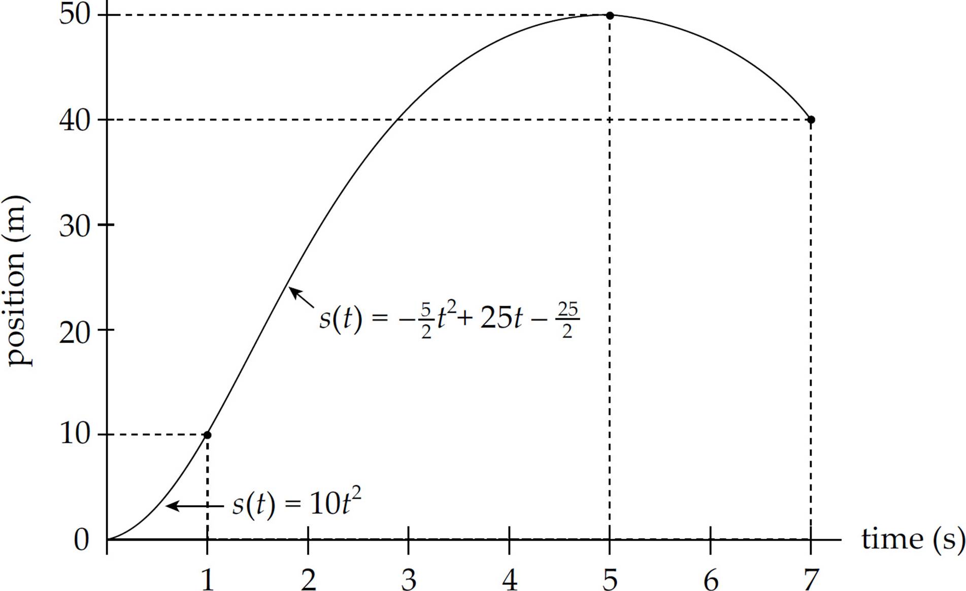
(c) The displacement is equal to the area bounded by the graph and the t-axis, taking areas above the t-axis as positive and those below as negative. In this case, the displacement from t = 0 to t = 5 s is equal to the area of the triangular region whose base is the segment along the t-axis from t = 0 to t = 5 s:
s (t = 0 to t = 5 s) = ![]() × base × height =
× base × height = ![]() (5 s)(20 m/s) = 50 m
(5 s)(20 m/s) = 50 m
The displacement from t = 5 s to t = 7 s is equal to the negative of the area of the triangular region whose base is the segment along the t-axis from t = 5 s to t = 7 s:
s (t = 5 s to t = 7 s) = –![]() × base × height = –
× base × height = –![]() (2 s)(10 m/s) = –10 m
(2 s)(10 m/s) = –10 m
Therefore, the displacement from t = 0 to t = 7 s is
 s (t = 0 to t = 5 s) +
  s (t = 5 s to t = 7 s) = 50 m + (–10 m) = 40 m
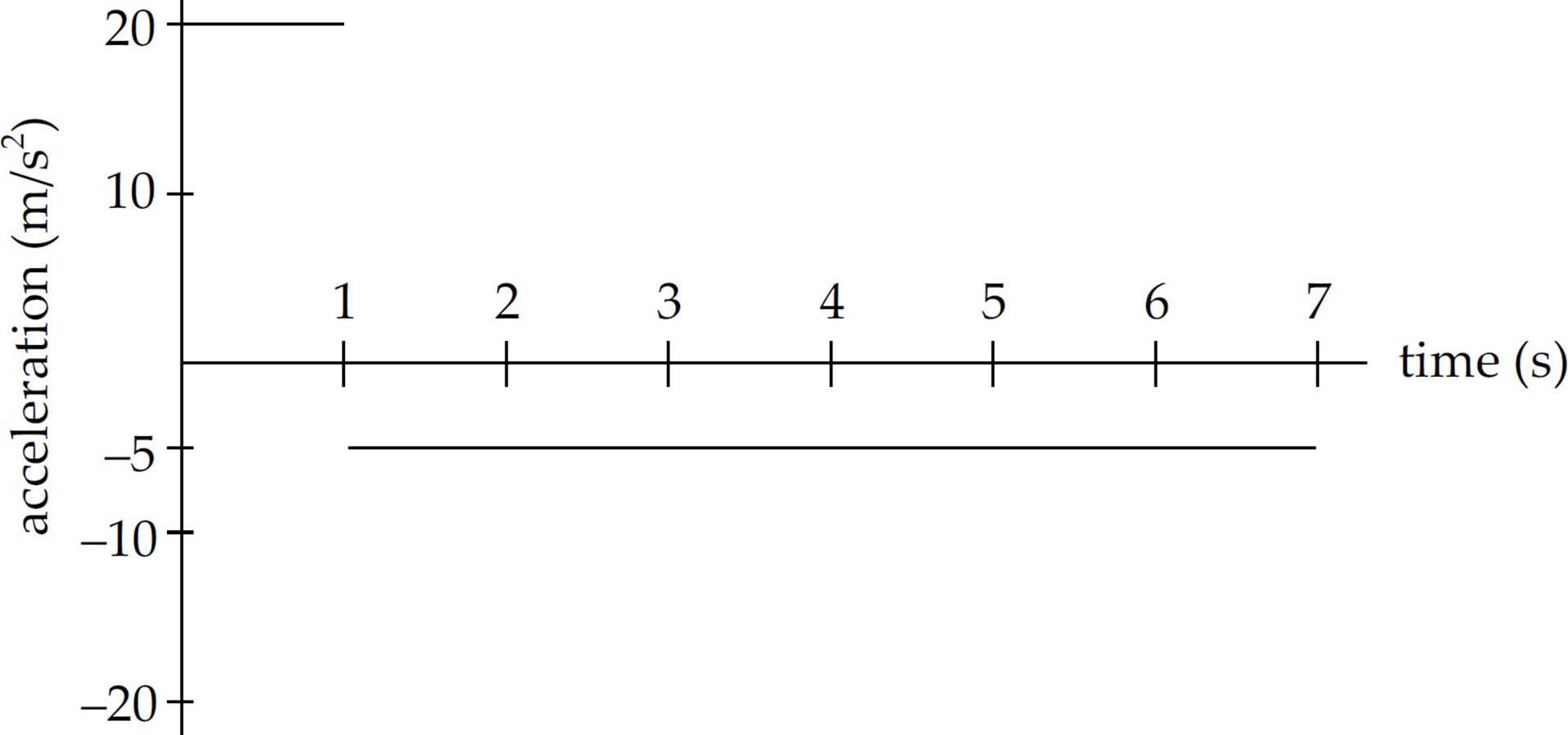
(d) The acceleration is the slope of the v vs. t graph. The segment of the graph from t = 0 to t = 1 s has a slope of a = v/ t = (20 m/s – 0)/(1 s – 0) = 20 m/s2, and the segment of the graph from t = 1 s to t = 7 s has a slope of a = v/t = (–10 m/s – 20 s)/(7 s – 1 s) = –5 m/s2. Therefore, the graph of a vs. t is
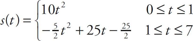
(e) One way to determine the displacement is to determine equations for v(t) and integrate to get s(t). The segment from t = 0 to t = 1 s connects the points (0, 0) and (1, 20); the slope is 20, and we get v = 20t. The segment from t = 1 to t = 7 connects the points (1, 20) and (7, –10); the slope is –5, and we get v = –5t + 25. In summary,
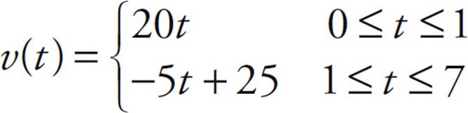
Therefore, since s(t) = ∫v(t) dt, we find that
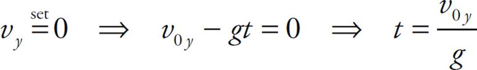
2. (a) The maximum height of the projectile occurs at the time at which its vertical velocity drops to zero:
The vertical displacement of the projectile at this time is computed as follows:
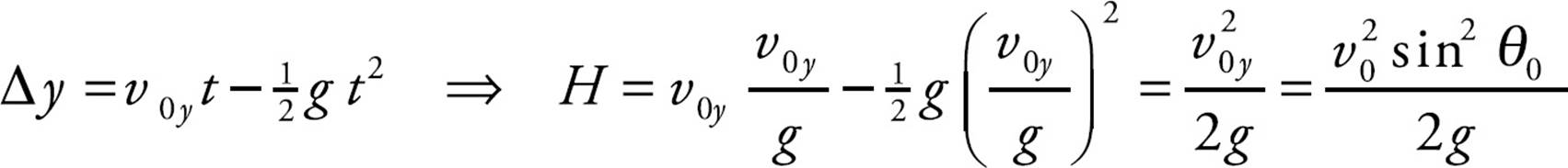
(b) The total flight time is equal to twice the time computed in part (a):
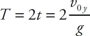
The horizontal displacement at this time gives the projectile’s range:

(c) For any given value of v0, the range,

will be maximized when sin 2θ0 is maximized. This occurs when 2θ0 = 90°, that is, when θ0 = 45°.
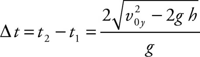
(d) Set the general expression for the projectile’s vertical displacement equal to h and solve for the two values of t:

Applying the quadratic formula, we find that
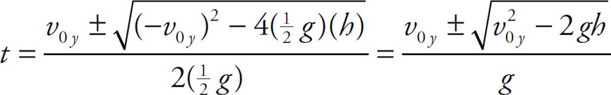
Therefore, the two times at which the projectile crosses the horizontal line at height h are
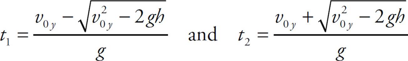
so the amount of time that elapses between these events is
3. (a) If we need to find how long the cannonball takes to reach the plane of the wall, we are dealing with the horizontal direction. The only equation we need is x = vxt.
220 = (50 cos 40°)t ⇒ t = 5.74 s
(b) To determine whether the cannonball hits the wall, we need to know the vertical displacement of the ball when it reaches the plane of the wall.
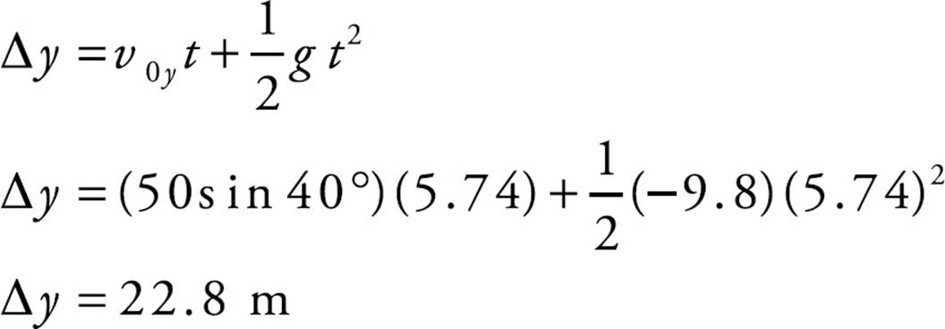
Since the wall is 30 m tall, the cannonball strikes the wall 7.2 m below the top of the wall.
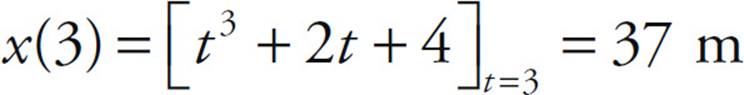
4. (a) Integrating a(t) with respect to time gives the velocity, v(t):
v(t) = ∫a(t)dt = ∫6t dt = 3t2 + v0 ⇒ v(t) = 3t2 + 2
Setting this equal to 14, we solve for t:
v(t) = 14 ⇒ 3t2 + 2 = 14 ⇒ t = 2 s
(Note that we discarded the solution t = –2.)
(b) Integrating v(t) with respect to time gives the position, x(t):
x(t) = ∫v(t) dt = ∫(3t2 + 2) dt = t3 + 2t + x0 ⇒ x(t) = t3 + 2t + 4
Therefore, the particle’s position at t = 3 s is
CHAPTER 5 REVIEW QUESTIONS
Section I: Multiple Choice
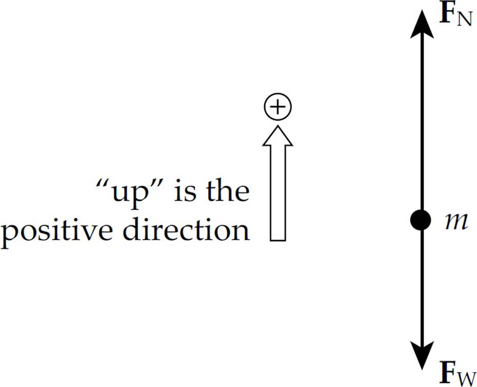
1. B Because the person is not accelerating, the net force he feels must be zero. Therefore, the magnitude of the upward normal force from the floor must balance that of the downward gravitational force. Although these two forces have equal magnitudes, they do not form an action/reaction pair because they both act on the same object (namely, the person). The forces in an action/reaction pair always act on different objects.
2. D First draw a free-body diagram.
The person exerts a downward force on the scale, and the scale pushes up on the person with an equal (but opposite) force, FN. Thus, the scale reading is FN, the magnitude of the normal force. Since FN – Fw = ma, we have FN = Fw + ma = (800 N) + [800 N/(10 m/s2)](5 m/s2) = 1200 N.
3. A The net force that the object feels on the inclined plane is mg sin θ, the component of the gravitational force that is parallel to the ramp. Since sin θ = (5 m)/(20 m) = 1/4, we have Fnet = (2 kg)(10 N/kg)(1/4) = 5 N.
4. C The net force on the block is F – Ff = F – µkFN = F – µkFw = (18 N) – (0.4)(20 N) = 10 N. Since Fnet = ma = (Fw/g)a, we find that 10 N = [(20 N)/(10 m/s2)]a, which gives a = 5 m/s2.
5. A The force pulling the block down the ramp is mg sin θ, and the maximum force of static friction is µsFN = µsmg cos θ. If mg sin θ is greater than µsmg cos θ, then there is a net force down the ramp, and the block will accelerate down. So, the question becomes, “Is sin θ greater than µs cos θ ?” Since cos 30°°≈ 0.87 and µs = 0.5, the answer is “yes.”
6. E One way to attack this question is to notice that if the two masses happen to be equal, that is, if M = m, then the blocks won’t accelerate (because their weights balance). The only expression given that becomes zero when M = m is the one given in choice (E). If we draw a free-body diagram,
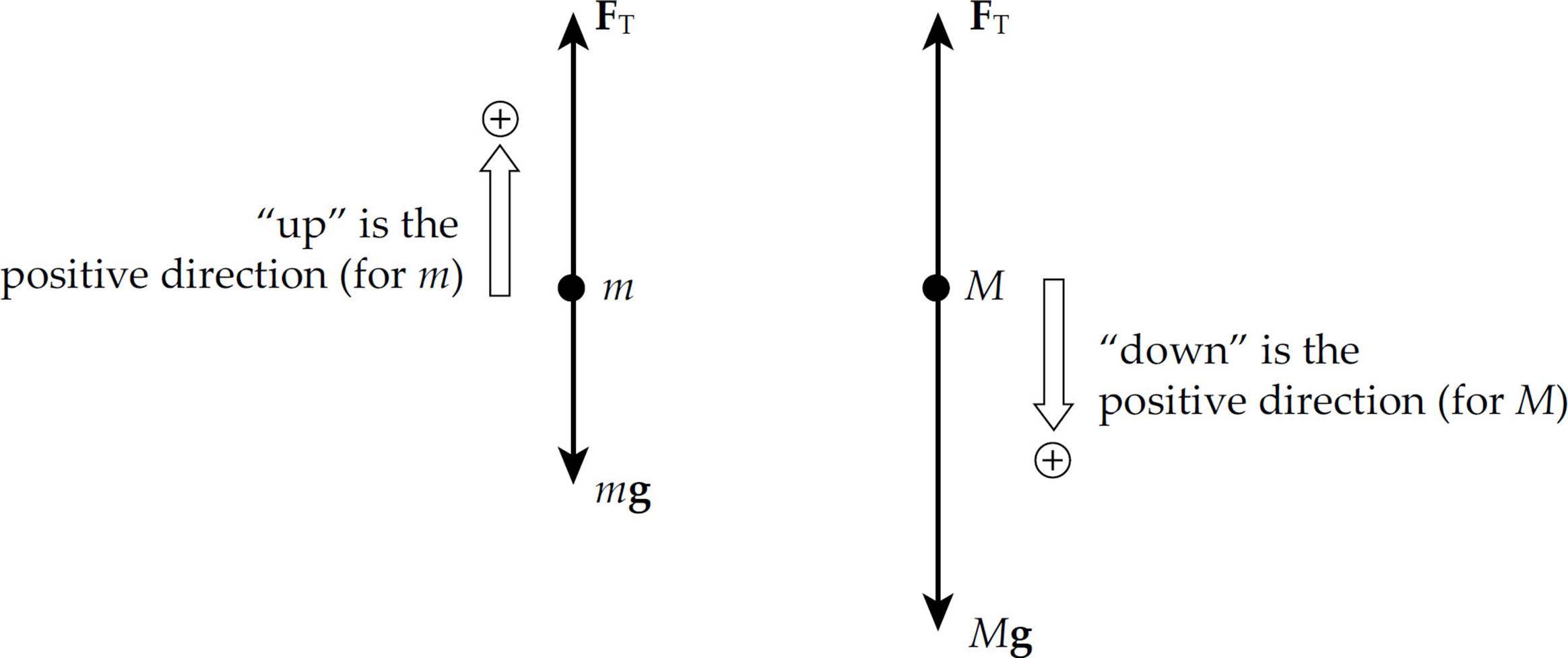
Newton’s Second Law gives us the following two equations:
FT – mg = ma (1)
Mg – FT = Ma (2)
Adding these equations yields Mg – mg = ma + Ma = (M + m)a, so
7. E If Fnet = 0, then a = 0. No acceleration means constant speed (possibly, but not necessarily, zero) with no change in direction. Therefore, statements B, C, and D are false, and statement A is not necessarily true.
8. D The horizontal motion across the frictionless tables is unaffected by (vertical) gravitational acceleration. It would take as much force to accelerate the block across the table on Earth as it would on the Moon. (If friction were taken into account, then the smaller weight of the block on the Moon would imply a smaller normal force by the table and hence a smaller frictional force. Less force would be needed on the Moon in this case.)
9. D The maximum force that static friction can exert on the crate is µsFN = µsFw = µsmg = (0.4)(100 kg)(10 N/kg) = 392 N. Since the force applied to the crate is only 344 N, static friction is able to apply that same magnitude of force on the crate, keeping it stationary. Note that choice (B) is incorrect because the static friction force is not the reaction force to F; both F and Ff (static) act on the same object (the crate) and therefore cannot form an action/reaction pair.
10. E Neither the velocity nor the acceleration is constant because the direction of each of these vectors is always changing as the object moves along its circular path. And the net force on the object is not zero, because a centripetal force must be acting to provide the necessary centripetal acceleration to maintain the object’s circular motion.
11. B When the bucket is at the lowest point in its vertical circle, it feels a tension force FT upward and the gravitational force Fw downward. The net force toward the center of the circle, which is the centripetal force, is FT – Fw. Thus,

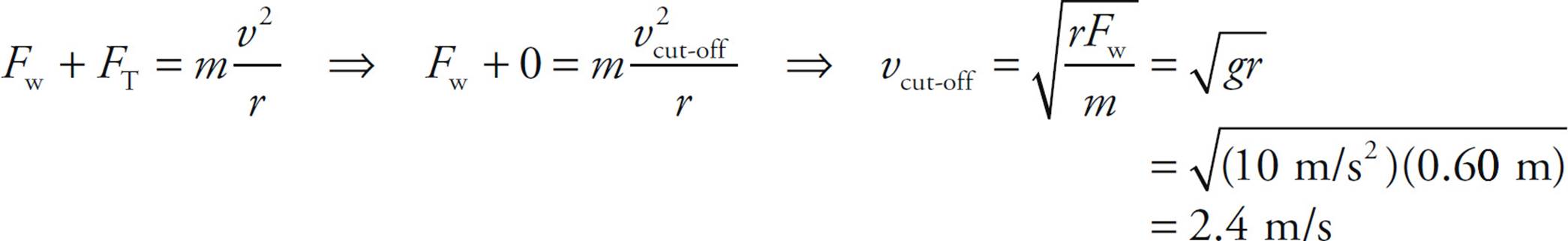
12. C When the bucket reaches the topmost point in its vertical circle, the forces acting on the bucket are its weight, Fw, and the downward tension force, FT. The net force, Fw + FT, provides the centripetal force. In order for the rope to avoid becoming slack, FT must not vanish. Therefore, the cut-off speed for ensuring that the bucket makes it around the circle is the speed at which FT just becomes zero; any greater speed would imply that the bucket would make it around. Thus,
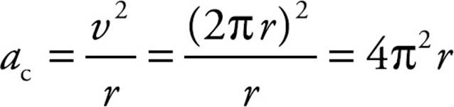
13. D Centripetal acceleration is given by the equation ac = v2/r. Since the object covers a distance of 2πr in 1 revolution each second,
Section II: Free Response
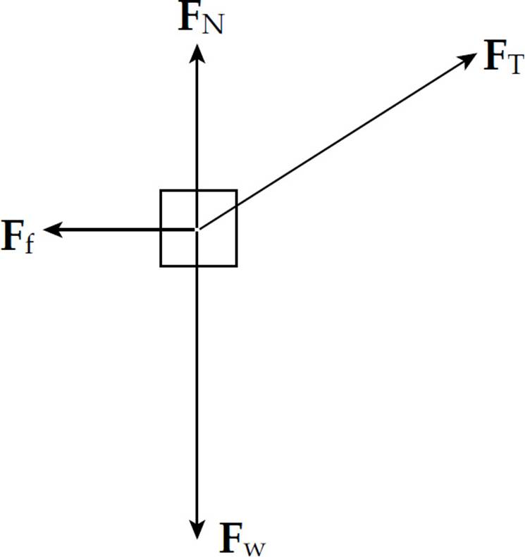
1. (a) The forces acting on the crate are FT (the tension in the rope), Fw (the weight of the block), FN (the normal force exerted by the floor), and Ff (the force of kinetic friction):
(b) First break FT into its horizontal and vertical components:
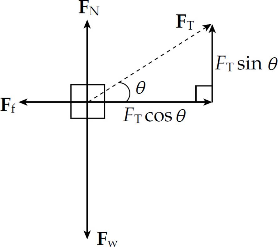
Since the net vertical force on the crate is zero, we have
FN + FT sin θ = Fw, so FN = Fw – FT sin θ = mg – FT sin θ
(c) From part (b), we see that the net horizontal force acting on the crate is
FT cos θ − Ff = FT cos θ − μFN = FT cos θ − μ(mg − FT sin θ)
so the crate’s horizontal acceleration across the floor is
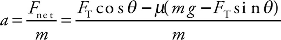
(d) In order to maximize the crate’s acceleration, we want to maximize the net horizontal force, FT cos θ − μ(mg − FT sin θ) = FT(cos θ + μ sin θ) − μ mg. Since FT, µ, m, and g are all fixed, maximizing the net horizontal force depends on maximizing the expression cos θ + μ sin θ
Call this f(θ). To determine the value of θ at which f(θ) = cos θ μ sin θ attains an extreme value, we take the derivative of f and set it equal to zero.
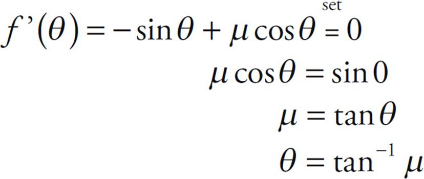
That this value of θ does indeed maximize f can be verified by noticing that for θ in the interval 0 ≤ θ ≤ ![]() π,
π, 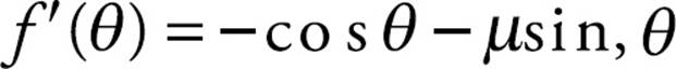 is always negative, and
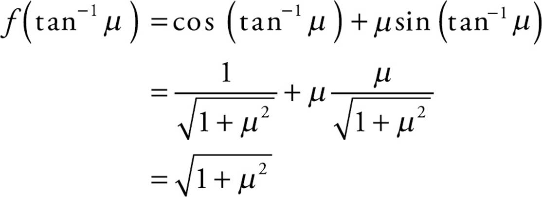
is greater than f (0) = 1 or f (![]() π) = µ, the values of f at the endpoints of the interval.
π) = µ, the values of f at the endpoints of the interval.
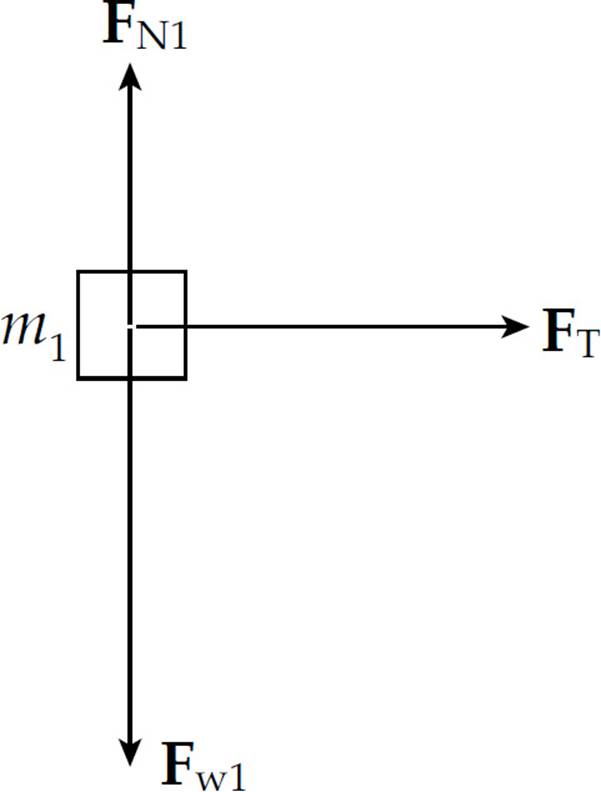
2. (a) The forces acting on Block #1 are FT (the tension in the string connecting it to Block #2), Fw1 (the weight of the block), and FN1 (the normal force exerted by the tabletop) as seen in the following figure:
(b) The forces acting on Block #2 are F (the pulling force), FT (the tension in the string connecting it to Block #1), Fw2 (the weight of the block), and FN2 (the normal force exerted by the tabletop) as seen in the following figure:
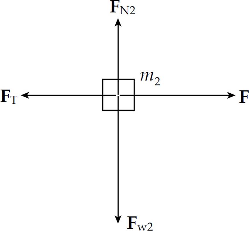
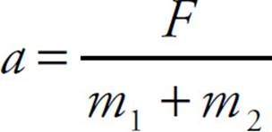
(c) Newton’s Second Law applied to Block #2 yields F – FT = m2a, and applied to Block #1 yields FT = m1a. Adding these equations, we find that F = (m1 + m2)a, so
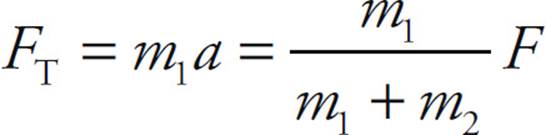
(d) Substituting the result of part (c) into the equation FT = m1a, we get
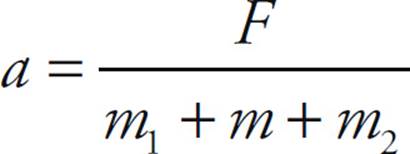
(e) (i) Since the force F must accelerate all three masses—m1, m, and m2—the common acceleration of all parts of the system is
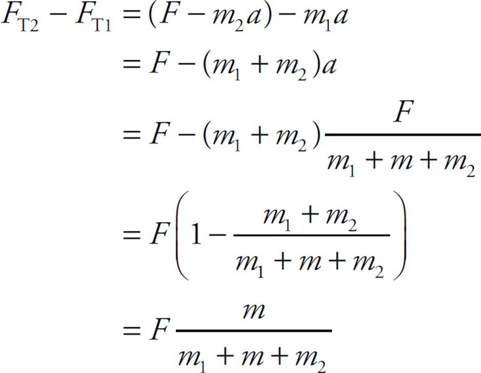
(e) (ii) Let FT1 denote the tension force in the connecting string acting on Block #1, and let FT2 denote the tension force in the connecting string acting on Block #2. Then, Newton’s Second Law applied to Block #1 yields FT1 = m1a and applied to Block #2 yields F – FT2 = m2a. Therefore, using the value for a computed above, we get
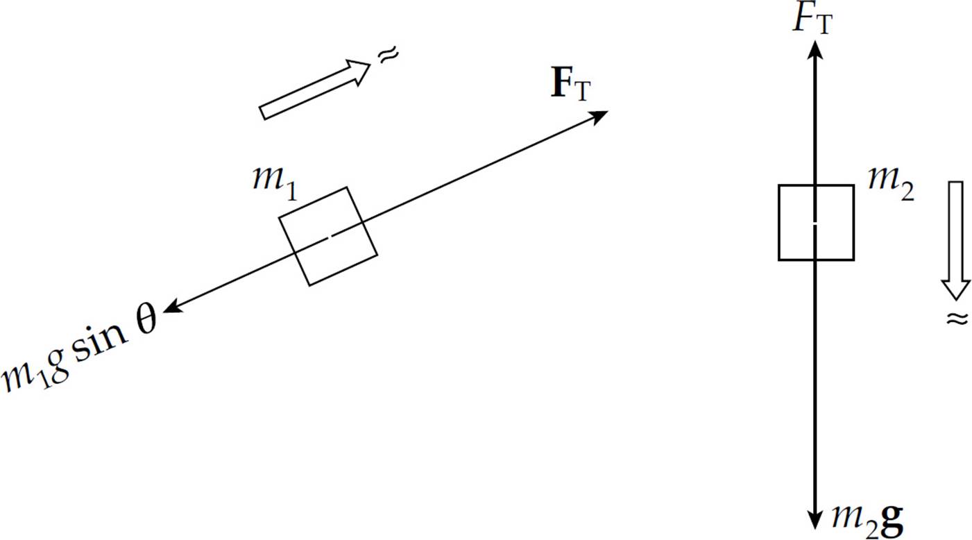
3. (a) First draw free-body diagrams for the two boxes.
Applying Newton’s Second Law to the boxes yields the following two equations:
FT – m1g sin θ = m1a (1)
m2g – FT = m2a (2)
Adding the equations allows us to solve for a:
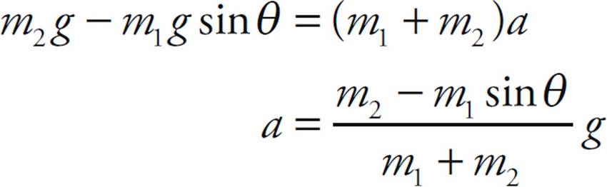
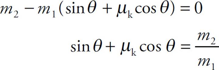
(i) For a to be positive, we must have m2 – m1 sin θ > 0, which implies that sin θ < m2/m1, or, equivalently, θ < sin–1(m2/m1).
(ii) For a to be zero, we must have m2 – m1 sin θ = 0, which implies that sin θ = m2/m1, or, equivalently, θ = sin–1(m2/m1).
(b) Including the force of kinetic friction, the force diagram for m1 is
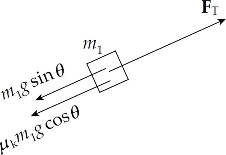
Since Ff = µkFN = µkm1g cos θ, applying Newton’s Second Law to the boxes yields the following two equations:
FT – m1g sin θ – µkmg cos θ = m1a (1)
m2g – FT = m2a (2)
Adding the equations allows us to solve for a:
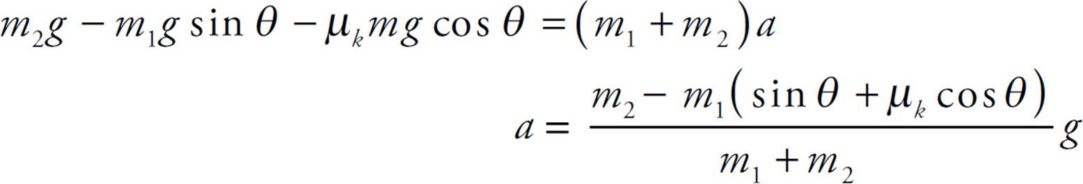
If we want a to be equal to zero (so that the box of mass m1 slides up the ramp with constant velocity), then
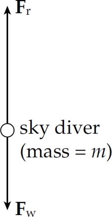
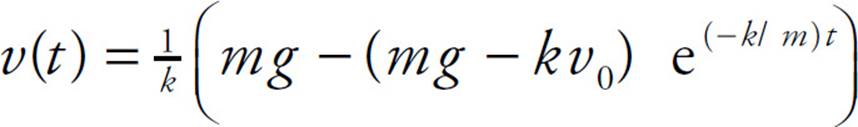
4. (a) The forces acting on the sky diver are Fr, the force of air resistance (upward), and Fw, the weight of the sky diver (downward) as seen in the following diagram:
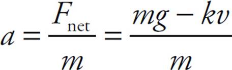
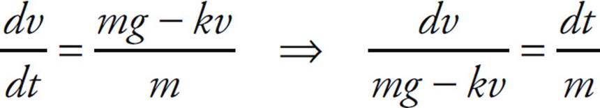
(b) Since Fnet = Fw – Fr = mg – kv = ma, the sky diver’s acceleration is
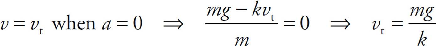
(c) Terminal speed occurs when the sky diver’s acceleration becomes zero, because then the descent velocity becomes constant. Setting the expression derived in part (b) equal to 0, we find the speed v = vt at which this occurs:
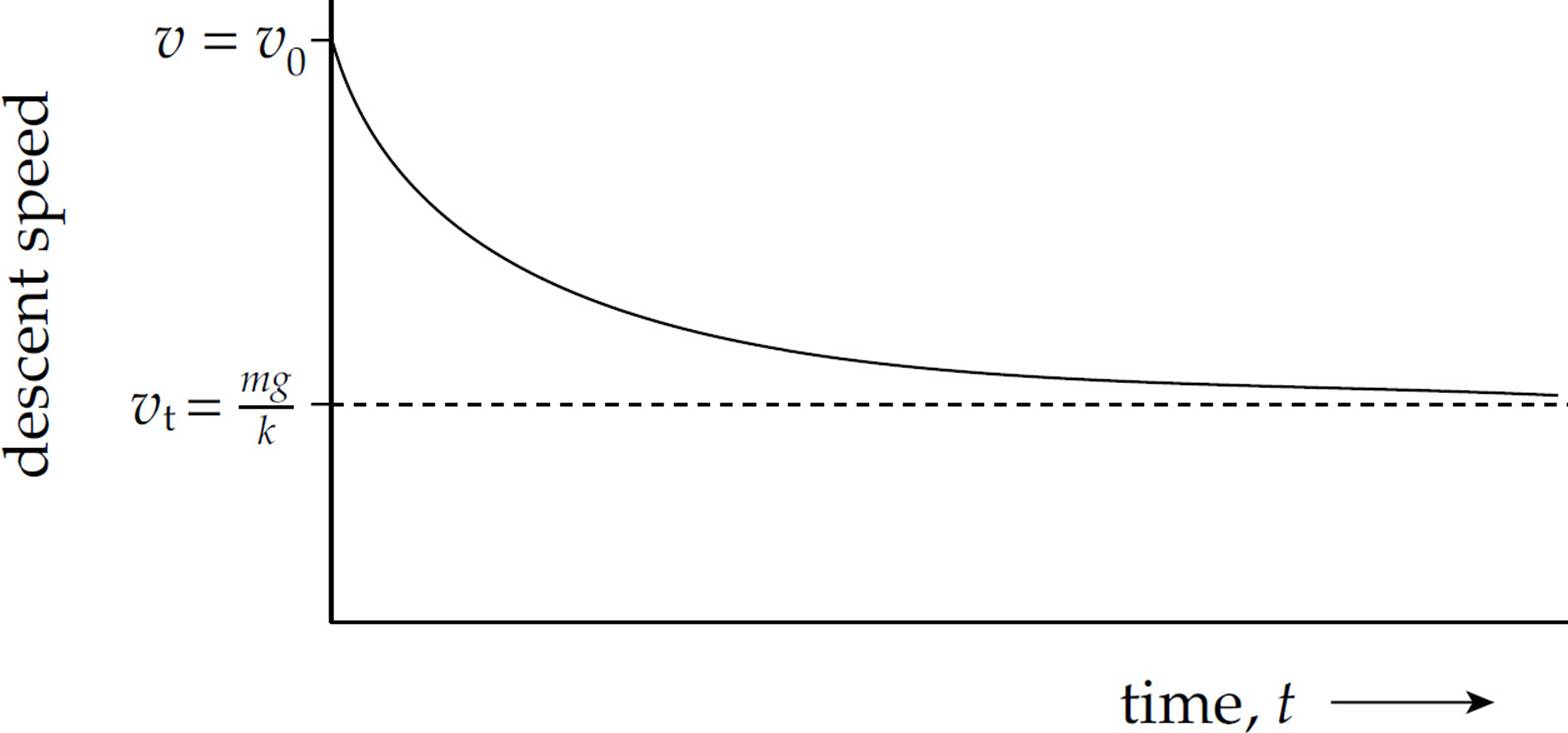
(d) The sky diver’s descent speed is initially v0. However, once the parachute opens, the force of air resistance provides a large, speed-dependent upward acceleration, causing her descent velocity to decrease. The slope of the v vs. t graph (the acceleration) is not constant but instead decreases to zero as her descent speed decreases from v0 tovt. Therefore, the graph is not linear.
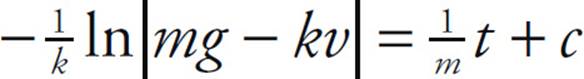
(e) Since a = dv/dt and, from part (b), a = (mg – kv)/m, we have
Integrating both sides of this equation gives
where c is a constant of integration. This equation can be rewritten in the form:
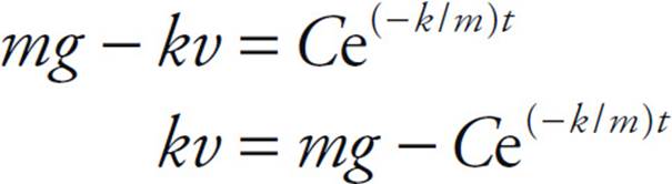
Since v = v0 at t = 0, we can determine the constant C:
kv0 = mg − C ⇒ C = mg − kv0
Therefore, the equation for the sky diver’s descent speed as a function of time is
5. (a) The forces acting on a person standing against the cylinder wall are gravity (Fw, downward), the normal force from the wall (FN, directed toward the center of the cylinder), and the force of static friction (Ff, directed upward) is depicted in the following diagram:
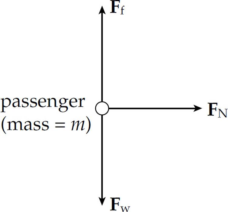
(b) In order to keep the passenger from sliding down the wall, the maximum force of static friction must be at least as great as the passenger’s weight: Ff (max) ≥ mg. Since Ff (max) = µsFN, this condition becomes
µsFN ≥ mg
Now, consider the circular motion of the passenger. Neither Ff nor Fw has a component toward the center of the path, so the centripetal force is provided entirely by the normal force
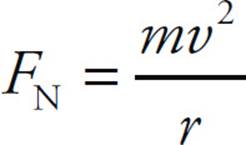
Substituting this expression for FN into the previous equation, we get
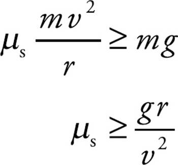
Therefore, the coefficient of static friction between the passenger and the wall of the cylinder must satisfy this condition in order to keep the passenger from sliding down.
(c) Since the mass m canceled out in deriving the expression for µs, the conditions are independent of mass. Thus, the inequality µs ≥ gr/v2 holds for both the adult passenger of mass m and the child of mass m/2.
6. (a) The forces acting on the car are gravity (Fw, downward), the normal force from the road (FN, upward), and the force of static friction (Ff, directed toward the center of curvature of the road) are seen in the diagram below:
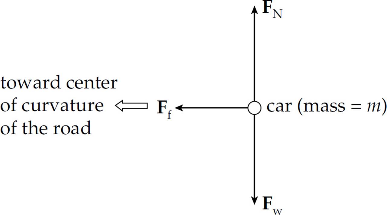
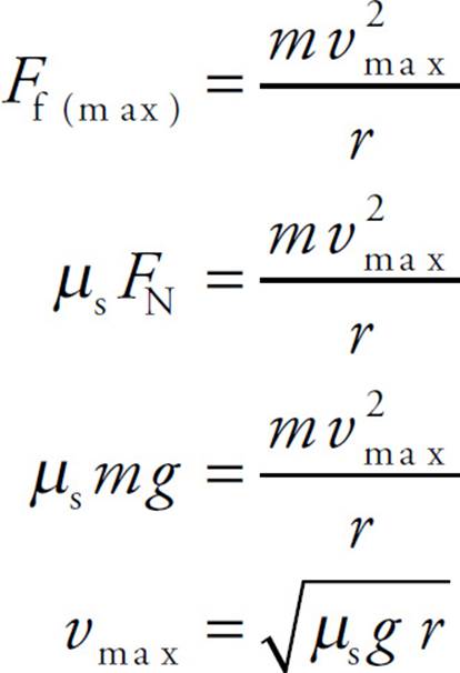
(b) The force of static friction [we assume static friction because we don’t want the car to slide (that is, skid)] provides the necessary centripetal force.
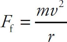
Therefore, to find the maximum speed at which static friction can continue to provide the necessary force, we write
(c) Ignoring friction, the forces acting on the car are gravity (Fw, downward) and the normal force from the road (FN, which is now tilted toward the center of curvature of the road) are seen in the following diagram:
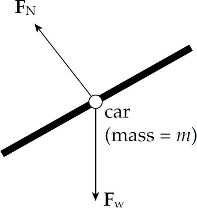
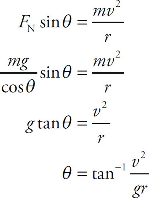
(d) Because of the banking of the turn, the normal force is tilted toward the center of curvature of the road. The component of FN toward the center can provide the centripetal force, making reliance on friction unnecessary.
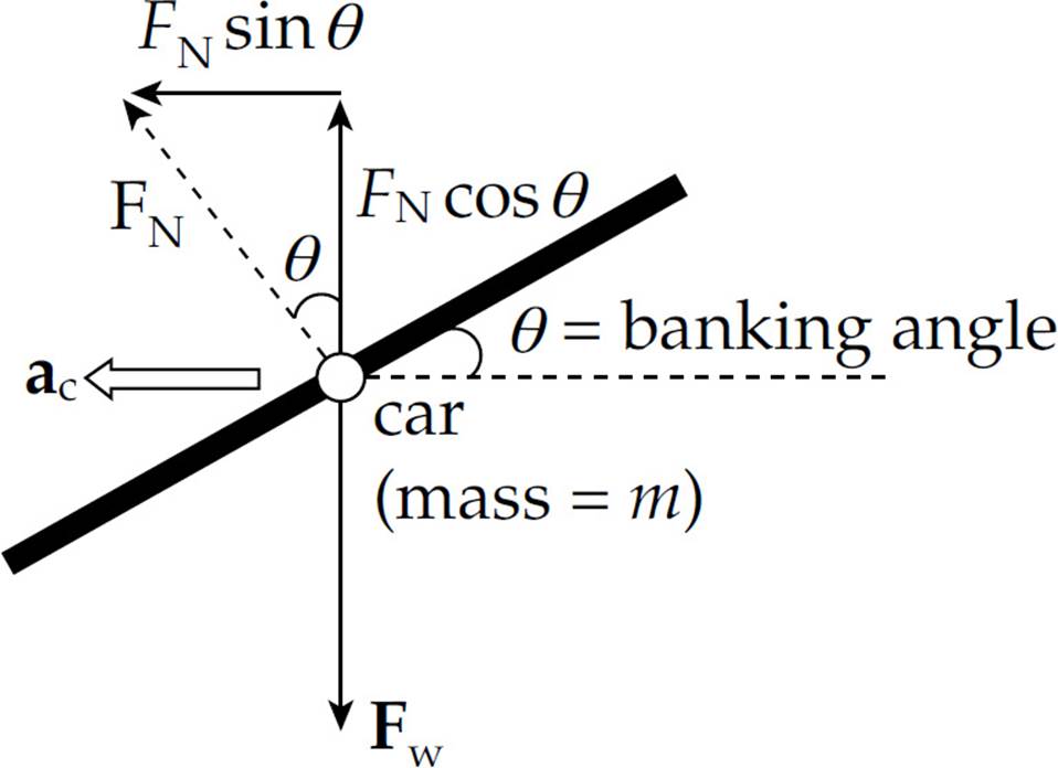
There’s no vertical acceleration, so FN cos θ = Fw = mg = 0, so FN = mg/cos θ. The component of FN toward the center of curvature of the turn, FN sin θ, provides the centripetal force.
CHAPTER 6 REVIEW QUESTIONS
Section I: Multiple Choice
1. A Since the force F is perpendicular to the displacement, the work it does is zero.
2. B By the work–energy theorem,

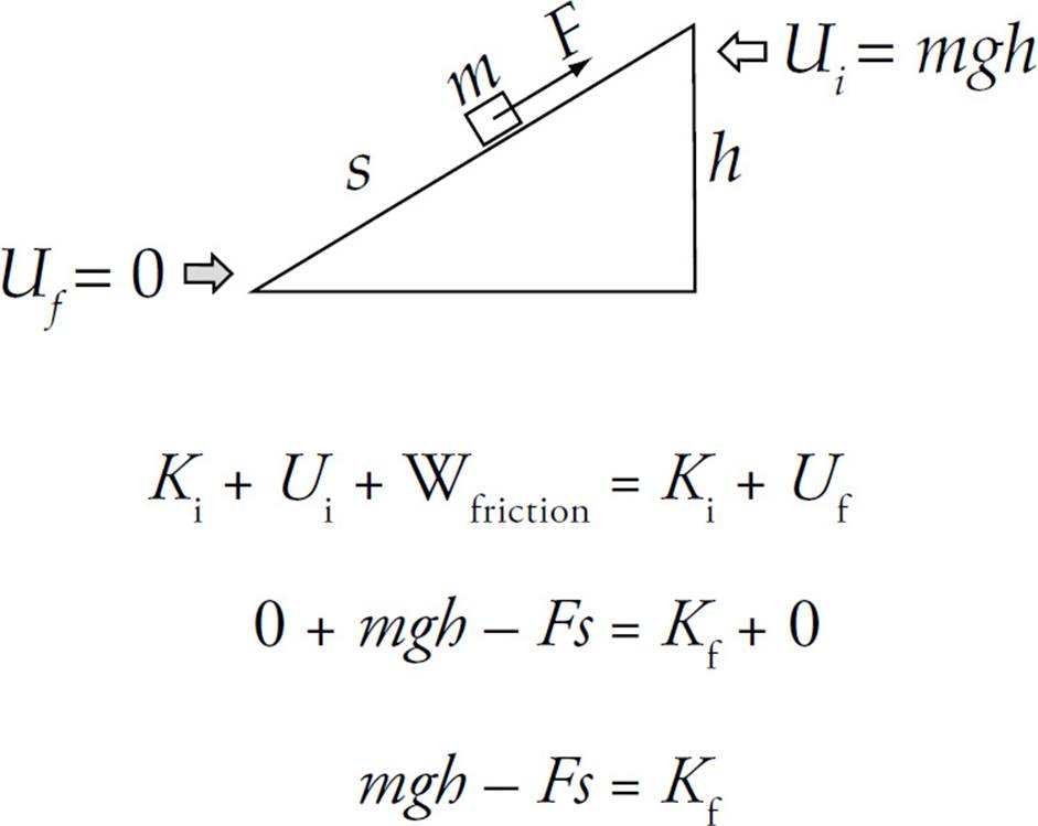
3. B Since the box (mass m) falls through a vertical distance of h, its gravitational potential energy decreases by mgh. The length of the ramp is irrelevant here.
4. C Since the centripetal force always points along a radius toward the center of the circle, and the velocity of the object is always tangent to the circle (and thus perpendicular to the radius), the work done by the centripetal force is zero. Alternatively, since the object’s speed remains constant, the work–energy theorem tells us that no work is being performed.
5. A The gravitational force points downward while the book’s displacement is upward. Therefore, the work done by gravity is –mgh = –(2 kg)(10 N/kg)(1.5 m) = –30 J.
6. D The work done by gravity as the block slides down the inclined plane is equal to the potential energy at the top (mgh).

7. D Since a nonconservative force (namely, friction) is acting during the motion, we use the modified Conservation of Mechanical Energy equation.
8. E Apply Conservation of Mechanical Energy (including the negative work done by Fr, the force of air resistance).
9. E Because the rock has lost half of its gravitational potential energy, its kinetic energy at the halfway point is half of its kinetic energy at impact. Since K is proportional to v2, if Kat halfway point is equal to ![]() Kat impact, then the rock’s speed at the halfway point is
Kat impact, then the rock’s speed at the halfway point is  its speed at impact.
10. D Using the equation P = Fv, we find that P = (200 N)(2 m/s) = 400 W.
Section II: Free Response
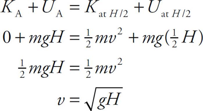
1. (a) Applying Conservation of Energy,
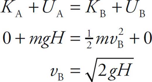
(b) Applying Conservation of Energy again,
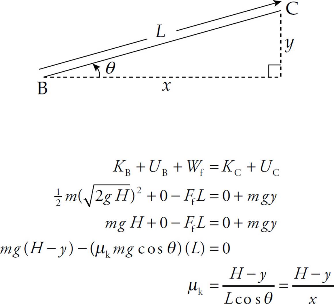
(c) By the work–energy theorem, we want the work done by friction to be equal (but opposite) to the kinetic energy of the box at Point B.

Therefore,
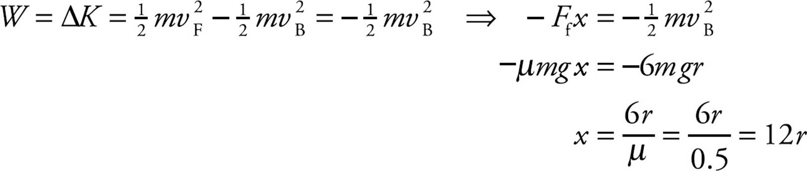
W = −mgH ⇒ −Ffx = −mgH ⇒ μkmgx = −mgH ⇒ μk = H / x
(d) Apply Conservation of Energy (including the negative work done by friction as the box slides up the ramp from B to C).
2. (a) The centripetal acceleration of the car at Point C is given by the equation a = v2C/r, where vC is the speed of the car at C. To find v2C, we apply Conservation of Energy.
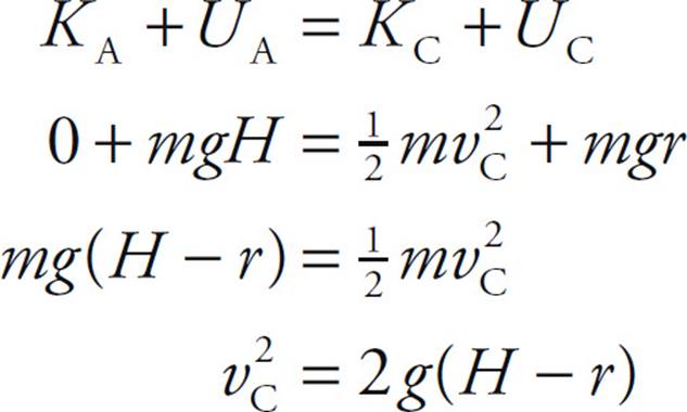
Therefore,
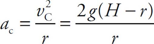
(b) When the car reaches Point D, the forces acting on the car are its weight, Fw, and the downward normal force, FN, from the track. Thus, the net force, Fw + FN, provides the centripetal force. In order for the car to maintain contact with the track, FN must not vanish. Therefore, the cut-off speed for ensuring that the car makes it safely around the track is the speed at which FN just becomes zero; any greater speed would imply that the car would make it around. Thus,

(c) Using the cut-off speed calculated in part (c), we now apply Conservation of Mechanical Energy.
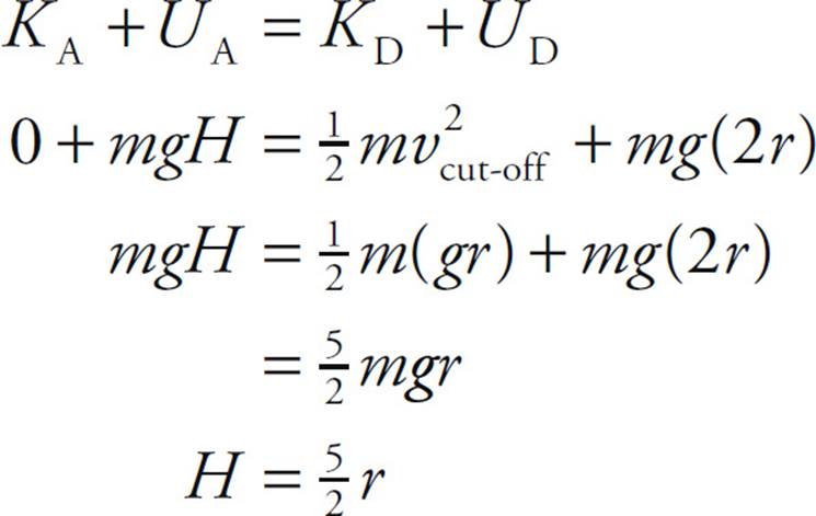
(d) First, we calculate the car’s kinetic energy at Point B; then, we determine the distance x the car must travel from B to F for the work done by friction to eliminate this kinetic energy. So, applying Conservation of Mechanical Energy, we find
Now, by the work–energy theorem,
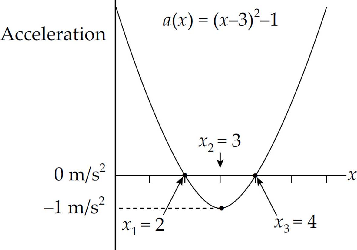
3. (a) The point where x = x1 is a local minimum of the function U(x), and the point where x = x3 is a local maximum. Therefore, at each of these locations, the derivative of U(x) must be equal to 0.

Therefore, x1 = 2 m and x3 = 4 m.
(b) If the particle’s total energy is E2 = ![]() (E1 + E3) =
(E1 + E3) = ![]() [U(x1) + U(x3)] =
[U(x1) + U(x3)] = ![]() [U(2) + U(4)] =
[U(2) + U(4)] = ![]() (4 J + 8 J) = 6 J, then the particle can oscillate between the points marked a and b in the following figure:
(4 J + 8 J) = 6 J, then the particle can oscillate between the points marked a and b in the following figure:
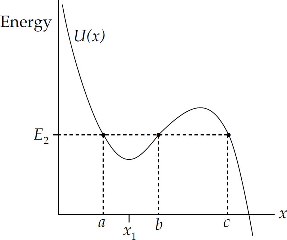
At points a and b the object has no kinetic energy (since U = E2 at these points), so these are the turning points at which the object momentarily comes to rest before being accelerated back toward x = x1 (where the potential energy is minimized). The particle cannot be found at x < a or within the interval b < x < c, since U > E2 in these intervals (and this would imply a negative K, which is impossible). If x > c, then since U decreases, K increases: the particle would move off in the + x direction with increasing speed.
(c) Since K + U = E, we have K = E – U. Therefore,
Therefore,
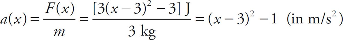
(d) Since F(x) = –dU/dx = –[3 – 3(x – 3)2] = 3(x – 3)2 – 3, dividing by m gives a.
(e) At x = ![]() x1, the particle’s energy is
x1, the particle’s energy is  .
.
This is the particle’s total energy because it has no initial kinetic energy (it is released from rest). As the particle passes through x = x1, its potential energy decreases to

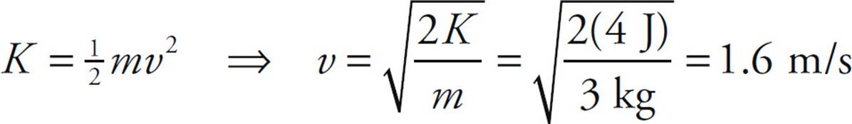
Therefore, since its total energy is 8 J, the particle’s kinetic energy at x = x1 must be K = E – U = 8 J – 4 J = 4 J. This implies that its speed is
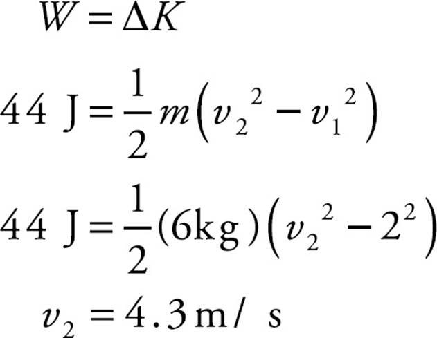
4. (a) Work equals the integral of the force and displacement.
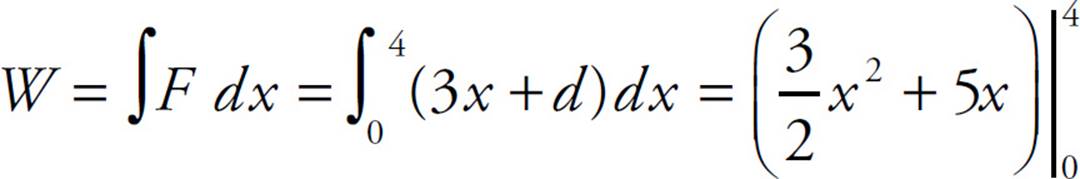
W = 44 J
(b) The work–energy theorem states the work done on an object equals the change in kinetic energy of the object.
CHAPTER 7 REVIEW QUESTIONS
Section I: Multiple Choice
1. C The magnitude of the object’s linear momentum is p = mv. If p = 6 kg · m/s and m = 2 kg, then v = 3 m/s. Therefore, the object’s kinetic energy is K = ![]() mv2 =
mv2 = ![]() (2 kg)(3 m/s)2 = 9 J.
(2 kg)(3 m/s)2 = 9 J.
2. C The impulse delivered to the ball, J = F t, equals its change in momentum. Since the ball started from rest, we have

3. E The impulse delivered to the box, J = Ft, equals its change in momentum. Thus,

4. D The impulse delivered to the ball is equal to its change in momentum. The momentum of the ball was mv before hitting the wall and m(–v) after. Therefore, the change in momentum is m(–v) – mv = –2mv, so the magnitude of the momentum change (and the impulse) is 2mv.
5. B By definition of perfectly inelastic, the objects move off together with one common velocity, v′, after the collision. By Conservation of Linear Momentum,
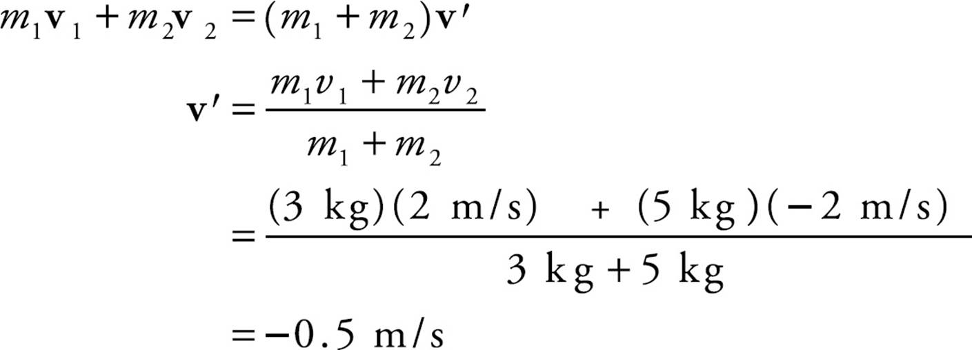
6. D First, apply Conservation of Linear Momentum to calculate the speed of the combined object after the (perfectly inelastic) collision.
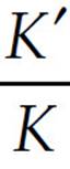
Therefore, the ratio of the kinetic energy after the collision to the kinetic energy before the collision is
 =
= 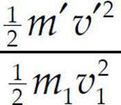 =
= 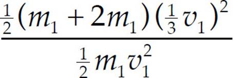 =
= ![]()
7. C Total linear momentum is conserved in a collision during which the net external force is zero. If kinetic energy is lost, then by definition, the collision is not elastic.
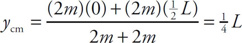
8. B First replace each rod by concentrating its mass at its center of mass position:
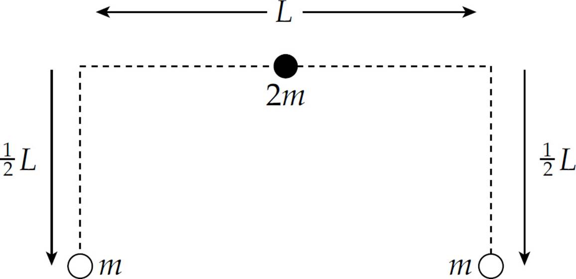
The center of mass of the two m’s is at their midpoint, at a distance of ![]() L below the center of mass of the rod of mass 2m:
L below the center of mass of the rod of mass 2m:
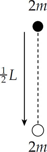
Now, applying the equation for locating the center of mass (letting y = 0 denote the position of the center of mass of the top horizontal rod), we find
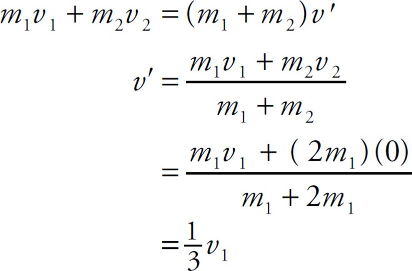
9. D The linear momentum of the bullet must have the same magnitude as the linear momentum of the block in order for their combined momentum after impact to be zero. The block has momentum MV to the left, so the bullet must have momentum MV to the right. Since the bullet’s mass is m, its speed must be v = MV/m.
10. C In a perfectly inelastic collision, kinetic energy is never conserved; some of the initial kinetic energy is always lost to heat and some is converted to potential energy in the deformed shapes of the objects as they lock together.
Section II: Free Response
1. (a) First draw a free-body diagram:
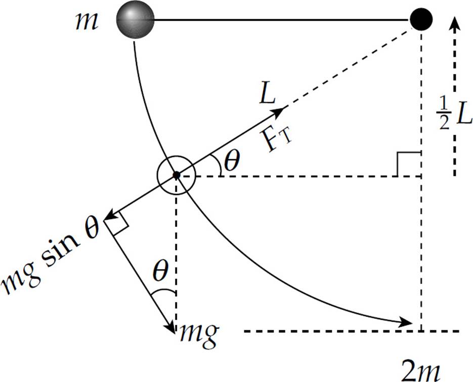
The net force toward the center of the steel ball’s circular path provides the centripetal force. From the geometry of the diagram, we have
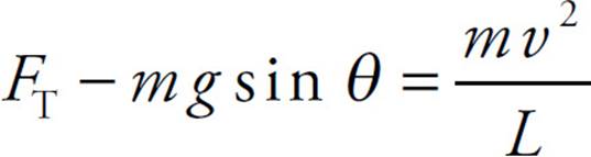
In order to determine the value of mv2, we use Conservation of Mechanical Energy:
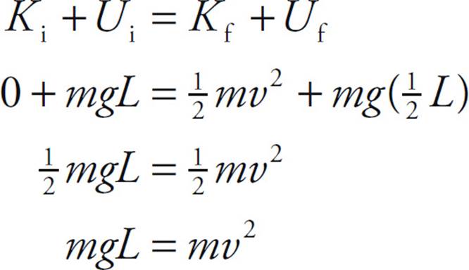
Substituting this result into Equation (*), we get
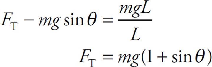
Now, from the free-body diagram we see that sin θ = ![]() L/L =
L/L = ![]() , so
, so
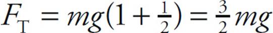
(b) Applying Conservation of Energy, we find the speed of the ball just before impact:
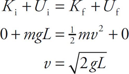
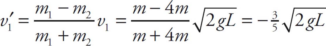
We can now use Conservation of Linear Momentum and the fact that kinetic energy is conserved to derive expressions for the speeds of the ball and block immediately after their collision. Since the collision is elastic, head-on, and the target object is at rest. The velocity of the block after the collision is
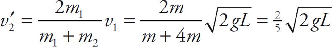
(c) We can quote the result of Chapter 7, Example 8 to find the velocity of the ball immediately after the collision:
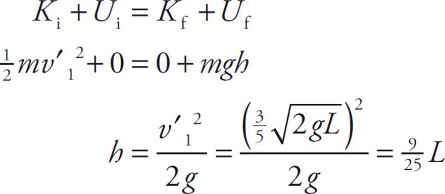
Now, applying Conservation of Mechanical Energy, we find
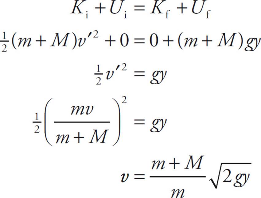
2. (a) By Conservation of Linear Momentum, mv = (m + M)v′, so v′ = 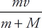
Now, by Conservation of Mechanical Energy,
(b) Use the result derived in part (a) to compute the kinetic energy of the block and bullet immediately after the collision:
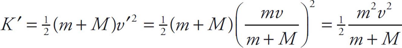
Since K = ![]() mv2, the difference is
mv2, the difference is
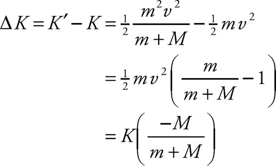
Therefore, the fraction of the bullet’s original kinetic energy that was lost is M/(m + M). This energy is manifested as heat (the bullet and block are warmer after the collision than before), and some was used to break the intermolecular bonds within the wooden block to allow the bullet to penetrate.
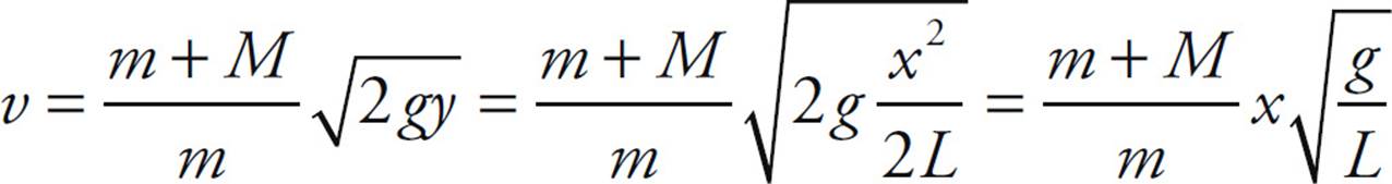
(c) From the geometry of the diagram,
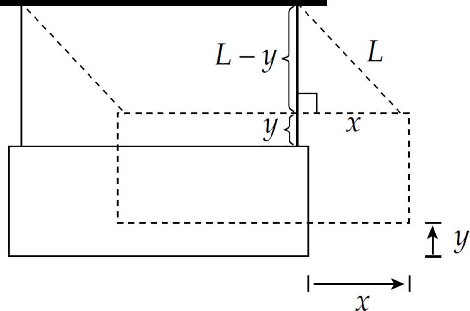
the Pythagorean theorem implies that (L − y)2 + x2 = L2. Therefore,
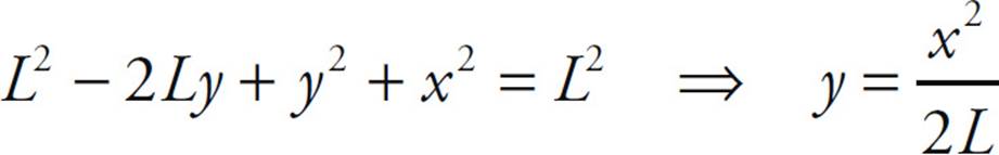
(where we have used the fact that y2 is small enough to be neglected). Substituting this into the result of part (a), we derive the following equation for the speed of the bullet in terms of x and L instead of y:
(d) No; momentum is conserved only when the net external force on the system is zero (or at least negligible). In this case, the block and bullet feel a net nonzero force that causes it to slow down as it swings upward. Since its speed is decreasing as it swings upward, its linear momentum cannot remain constant.
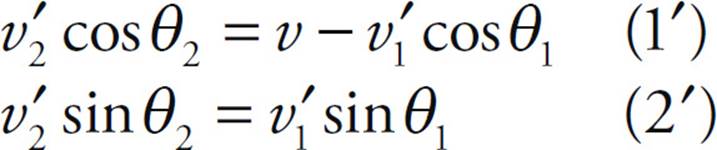
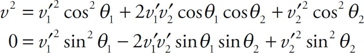
3. (a) To apply Conservation of Linear Momentum to the collision, we recognize that momentum is a vector quantity and, therefore, linear momentum must be conserved separately in the horizontal (x) and vertical (y) directions. Before the collision, the linear momentum was horizontal only. Therefore, in the x direction:
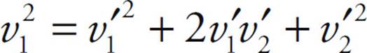
mv = mv′1 cos θ1 + mv′2 cos θ2 ⇒ v = v′1 cos θ1 + v′2 cos θ2 (1)
in the y direction:
0 = mv′1 sin θ1 − mv′2 sin θ2 ⇒ 0 = v′1 sin θ1 − v′2 sin θ2 (2)
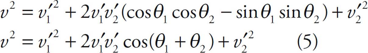
Since the collision is elastic, kinetic energy is also conserved; thus,
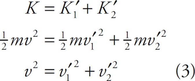
In order to find 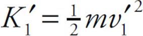 in terms of K1 and θ1 only, we need to manipulate the equations to eliminate v2 and θ2. The following approach will do this. Rewrite Equations (1) and (2) in the following forms:
Square both equations and add, exploiting the trig identity cos2θ + sin2θ = 1:
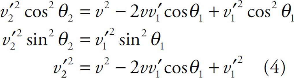
This eliminates θ2. Now, to eliminate v2, substitute the value of v22 from Equation (3) into Equation (4):
Therefore, we can write

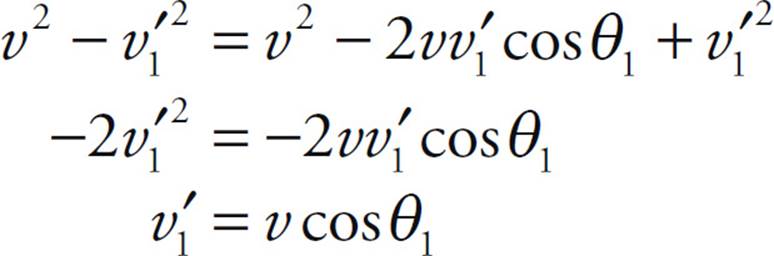
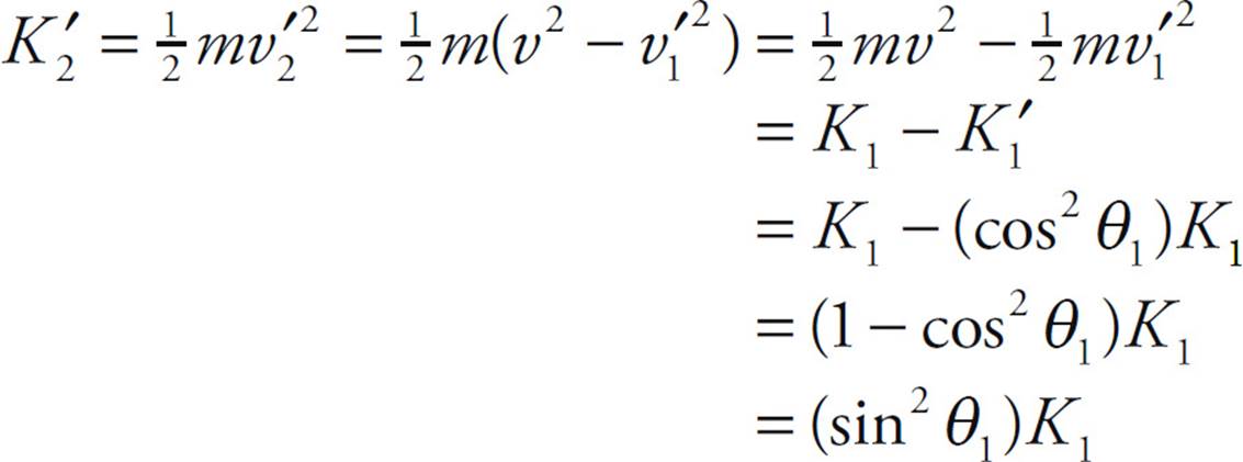
(b) Since, by Equation (3), 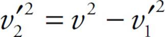 , the result of part (a) gives
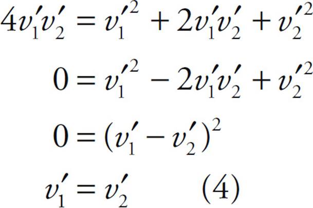
(c) Square Equation (1) and Equation (2) from part (a) and add:
Adding gives:
Now, since by Equation (3), 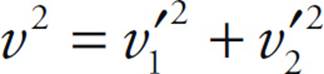 , combining this with equation (5) gives
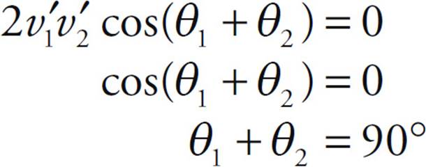
Thus, the objects’ post-collision velocity vectors are perpendicular to each other.
CHAPTER 8 REVIEW QUESTIONS
Section I: Multiple Choice
1. B We use the equation v = rω:
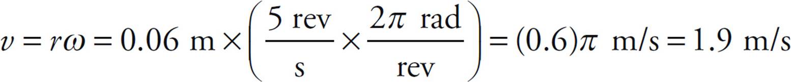
2. E Use the equation distance = rate × time with v = rω:

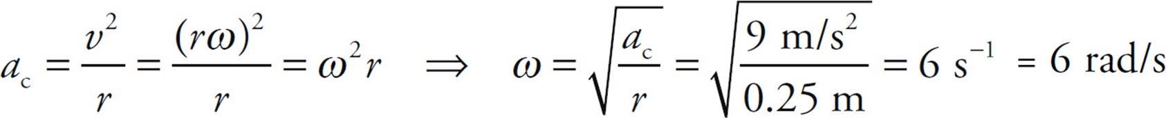
3. C By combining the equation for centripetal acceleration, ac = v2/r, with v = rω, we find
4. C Use Big Five #3 for rotational motion.

5. D The torque is τ = rF = (0.20 m)(20 N) = 4 N · m.
6. D From the diagram,
we calculate that
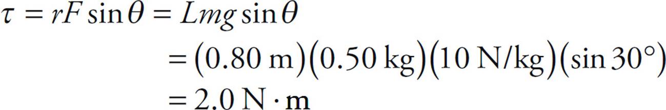
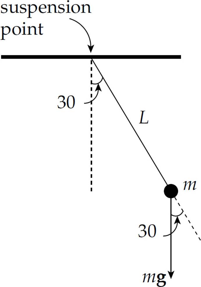
7. B The stick will remain at rest in the horizontal position if the torques about the suspension point are balanced.
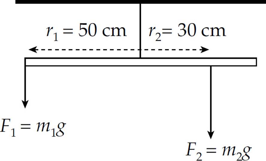
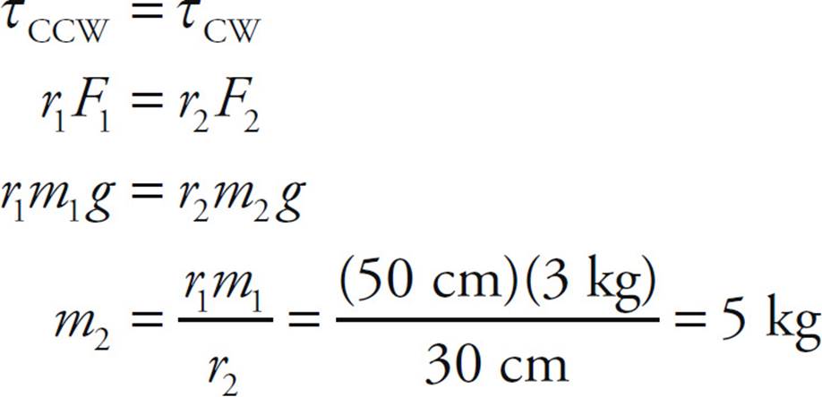
8. A Each of the four masses is at distance L from the rotation axis, so

Note that the length of the rectangular frame, ![]() L, is irrelevant here.
L, is irrelevant here.
9. A By Conservation of Mechanical Energy,
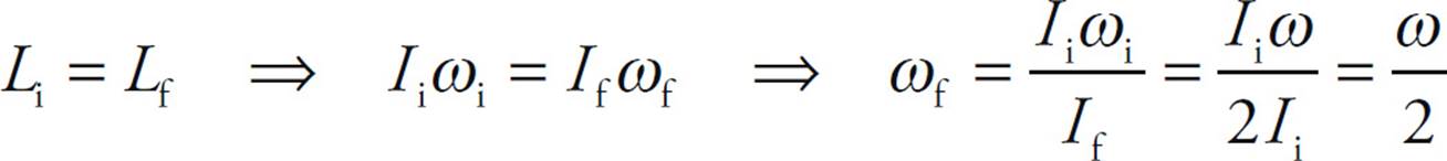
10. B By Conservation of Angular Momentum,
Section II: Free Response
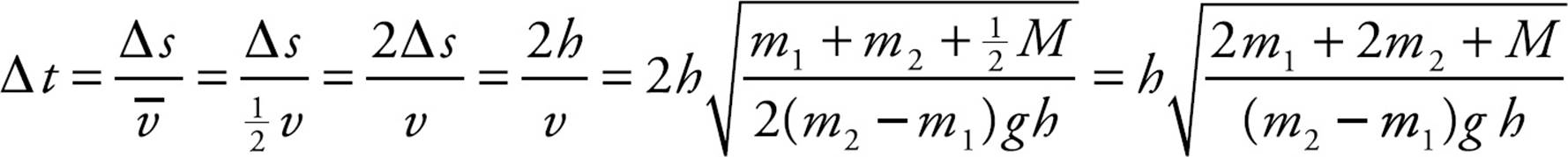
1. (a) Apply Conservation of Mechanical Energy, remembering to take into account the translational kinetic energy of the falling block (m2), the rising block (m1), and the rotating pulley.
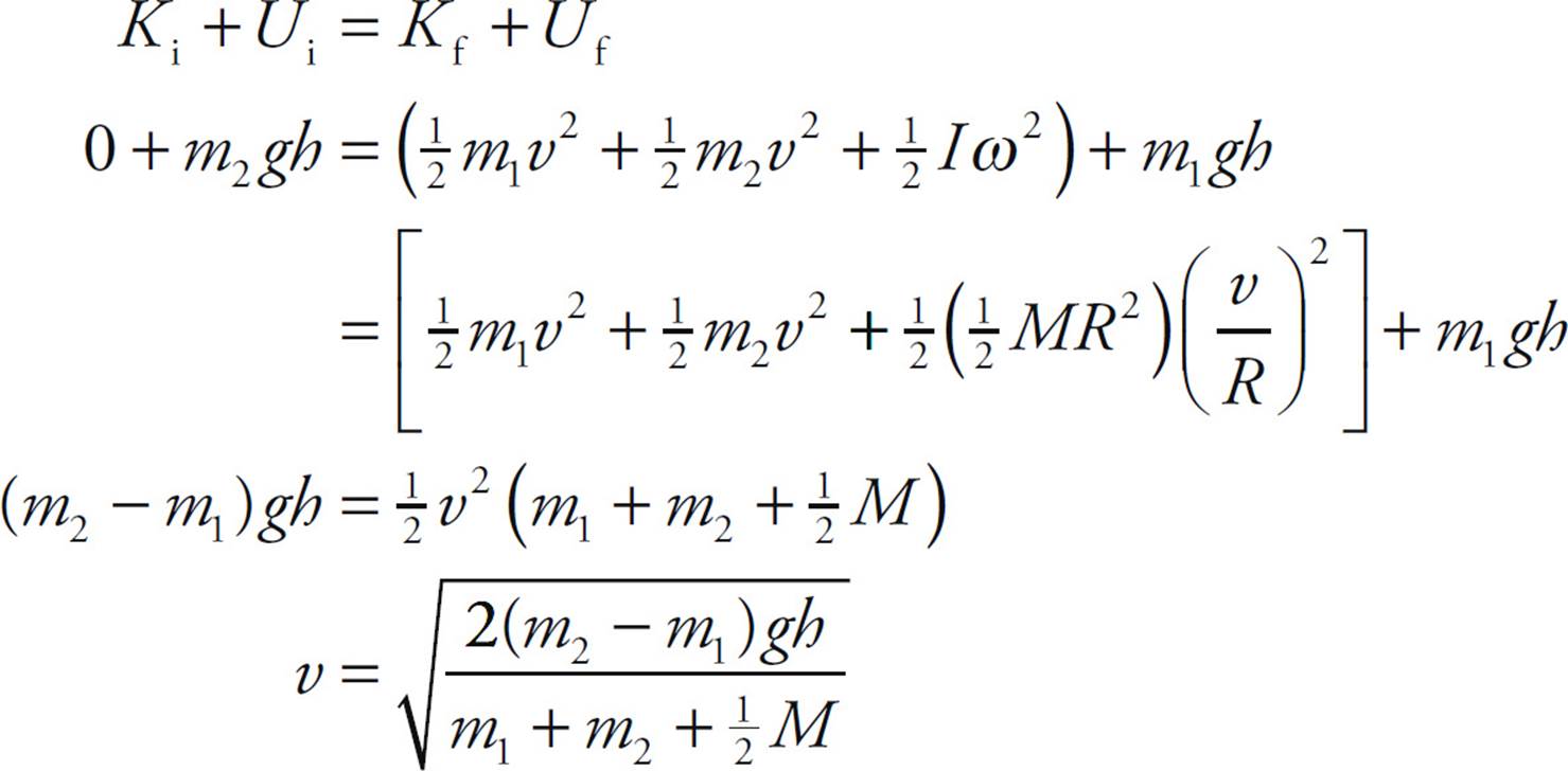
(b) Using the equation v = Rω, we find
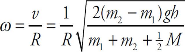
(c) Since Block 2 (and Block 1) moved a distance h during the motion, a point on the rim of the pulley must also move through a distance h. Therefore,  θ = h/R.
(d) Use Big Five #1 (for translational motion).
2. (a) Consider the following diagram of the disk rolling down the ramp:
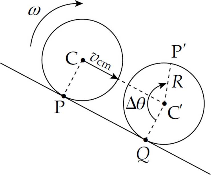
In a time interval  t, the center of mass moves from C to C′, a distance equal to vcmt. While this is occurring, Point P on the rim moves to the new position P′. In order for there to be no slipping, the arc length P′Q, which is Rθ, must equal the straight line distance PQ. But PQ = CC′, so we have
vcmt = Rθ ⇒ vcm t = R ω
  t ⇒ vcm = R ω
(b) One way to derive the desired result is to notice that the velocity of T relative to P is equal to the velocity of T relative to C plus the velocity of C relative to P (vTP = vTC + vCP).
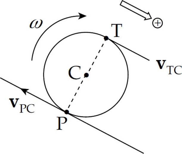
Since the velocity of C relative to P is the opposite of the velocity of P relative to C (vCP = –vPC), we have vTP = vTC – vPC. Relative to C, point T is moving forward with speed Rω and point P is moving backward with speed Rω. Therefore, vTP = (+Rω) – (–Rω) = +2Rω = 2vcm.
Another method is to think of the disk as executing pure rotation instantaneously about the contact Point P. From this point of view (with P as pivot), the distance to C is R, and the distance to T is 2R. Therefore, the linear speed of C is Rω and that of T is 2Rω, which implies that the linear speed of point T is twice that of point C, as desired.
(c) The speed with which the block rises, vb, is equal to the speed at which the thread wraps around the cylinder, which is 2vcm, as shown in part (b). Therefore, differentiating the equation vb = 2vcm with respect to time, we get ab = 2acm. That is, the acceleration of the block is equal to twice that of the (center of mass of the) cylinder.
(d) First draw free-body diagrams for the block and the cylinder.
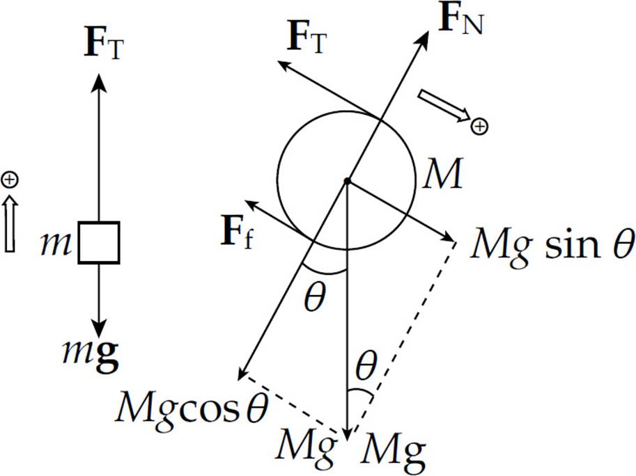
Newton’s Second Law applied to the block yields FT – mg = mab. Since ab = 2acm, we write
FT – mg = 2macm (1)
Newton’s Second Law applied to the forces on the cylinder gives us
Mg sin θ – Ff – FT = Macm (2)
The tension force and friction force each exert a torque about the center of mass of the cylinder. The torque of the friction force is counterclockwise (positive), and the torque of the tension force is negative. Therefore, τnet = Iα becomes
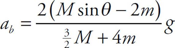
Now for the algebra. Adding Equations (2) and (3) gives 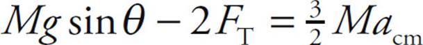 . Multiplying both sides of Equation (1) by 2 gives 2FT - 2mg = 4macm. Adding these last two equations allows us to find acm, the linear acceleration of the cylinder.

(e) Since ab = 2acm, the acceleration of the block is
3. (a) Consider a rod of length 2L with the pivot at its center. Since the rod is uniform, its linear mass density is M/(2L), so the mass of a segment of length dx is M dx/(2L).
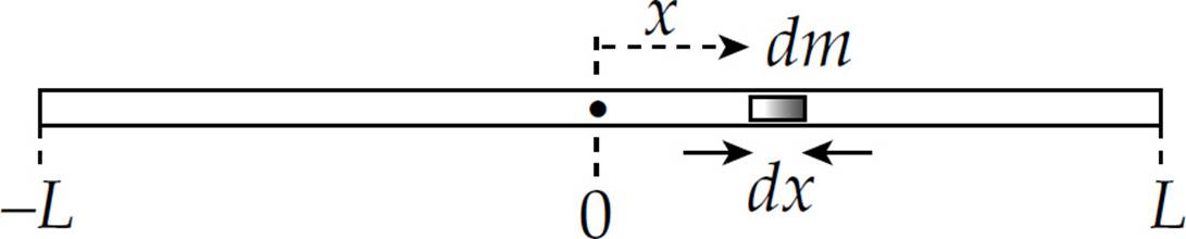
Applying the definition of I, we find

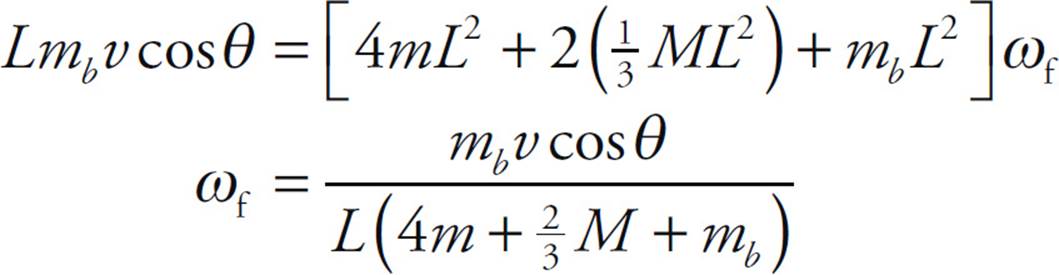
(b) We apply Conservation of Angular Momentum to the collision of the bullet and assembly. Since the rods were at rest prior to the bullet’s impact, only the bullet had angular momentum. With respect to the pivot point, its angular momentum was Lmbv⊥, where v⊥ is the component of v that is perpendicular to the radius vector. From the definition of θ in the figure given with the question, v⊥ = v cos θ. After the collision, the angular momentum is equal to the angular velocity of the assembly times the rotational inertia of the four clay balls, the two rods, and the embedded bullet. We get
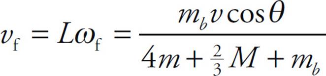
(c) Using the equation v = Rω, we find that
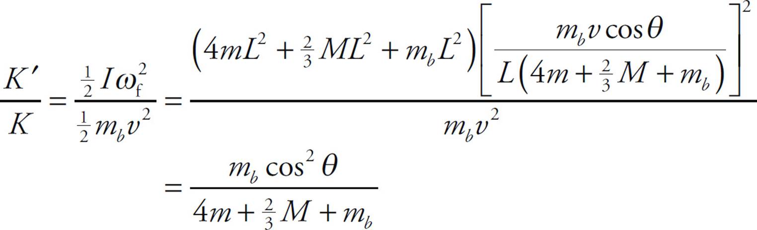
(d) After the collision, the assembly has rotational kinetic energy. The ratio of this energy to the (translational) kinetic energy of the bullet before impact is
CHAPTER 9 REVIEW QUESTIONS
Section I: Multiple Choice
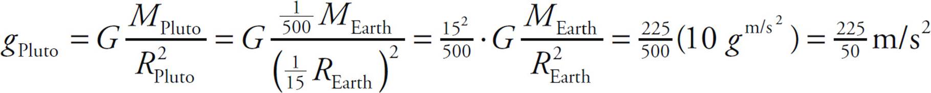
1. A Gravitational force obeys an inverse-square law: Fgrav ∝ 1/r2. Therefore, if r increases by a factor of 2, then Fgrav decreases by a factor of 22 = 4.
2. E Mass is an intrinsic property of an object that does not change with location. This eliminates choices A and C. If an object’s height above the surface of Earth is equal to 2RE, then its distance from the center of Earth is 3RE. Thus, the object’s distance from Earth’s center increases by a factor of 3, so its weight decreases by a factor of 32 = 9.
3. C The gravitational force that the Moon exerts on the planet is equal in magnitude to the gravitational force that the planet exerts on the moon (Newton’s Third Law).
4. D The gravitational acceleration at the surface of a planet of mass M and radius R is given by the equation g = GM/R2. Therefore,
5. B The gravitational pull by Earth provides the centripetal force on the satellite, so GMm/R2 = mv2/R. This gives ![]() mv2 = GMm/2R, so the kinetic energy K of the satellite is inversely proportional to R. Therefore if R increases by a factor of 2, then K decreases by a factor of 2.
mv2 = GMm/2R, so the kinetic energy K of the satellite is inversely proportional to R. Therefore if R increases by a factor of 2, then K decreases by a factor of 2.
6. E The gravitational pull by Jupiter provides the centripetal force on its moon:
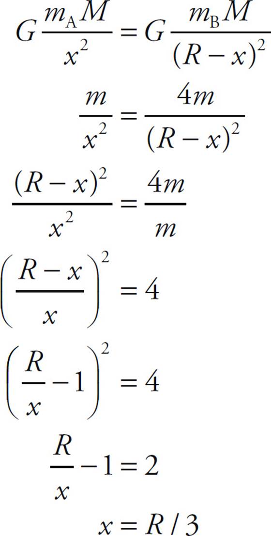
7. E Let the object’s distance from Body A be x; then its distance from Body B is R – x. In order for the object to feel no net gravitational force, the gravitational pull by A must balance the gravitational pull by B. Therefore, if we let M denote the mass of the object, then
8. B Kepler’s Third Law says that T2 ∝ R3 for a planet with a circular orbit of radius R. Since T ∝ R3/2, if R increases by a factor of 9, then T increases by a factor of 93/2 = (32)3/2 = 33 = 27.
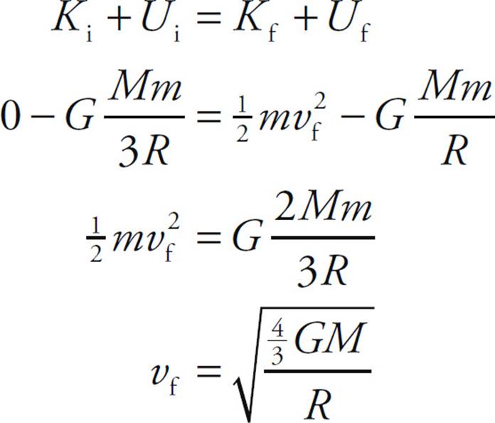
9. D Apply Conservation of Mechanical Energy:
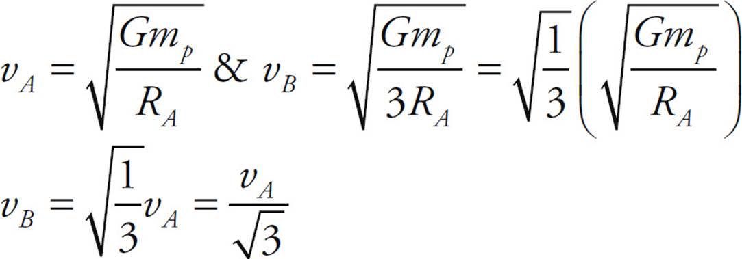
10. E The force of gravity is the centripetal force, so we can solve for the velocity of each satellite and compare them.
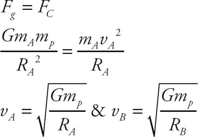
Now since RB = 3RA
Section II: Free Response
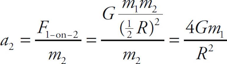
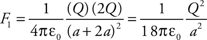
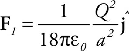
1. (a) Combining Newton’s Second Law with the Law of Gravitation, we find

The direction of a1 is toward Sphere 2.
(b) Combining Newton’s Second Law with the Law of Gravitation, we find
The direction of a2 is toward Sphere 1.
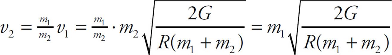
(c) Since the two spheres start from rest, the total linear momentum of the system is clearly zero. Since no external forces act (we’re in “deep space”), the total momentum must remain zero during their motion toward each other. Therefore, the magnitude of Sphere 1’s linear momentum, m1v1, must always equal the magnitude of Sphere 2’s linear momentum, m2v2. Thus, v2 = (m1/m2)v1. With this result, we can apply Conservation of Mechanical Energy:
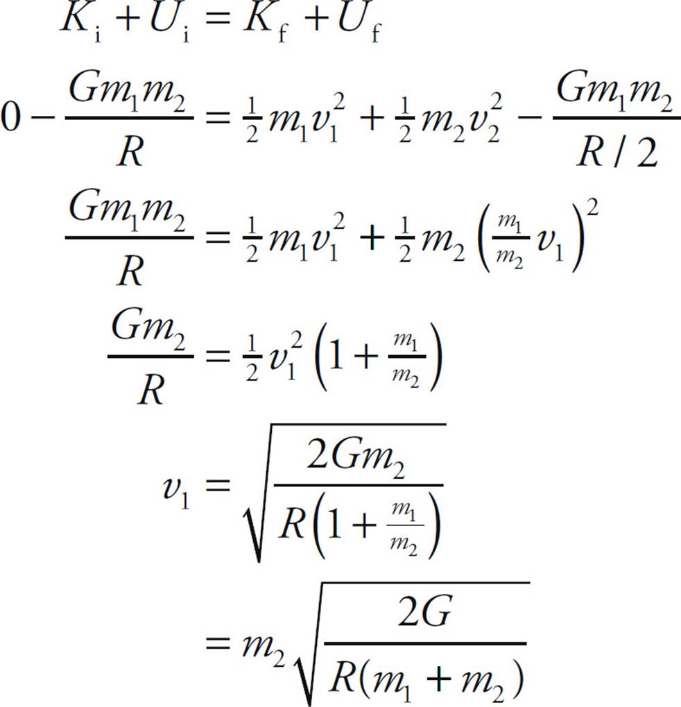
(d) Using the result of part (c) and the relationship v2 = (m1/m2)v1, we get
(e) The centripetal force on each sphere is provided by the gravitational pull by the other sphere.
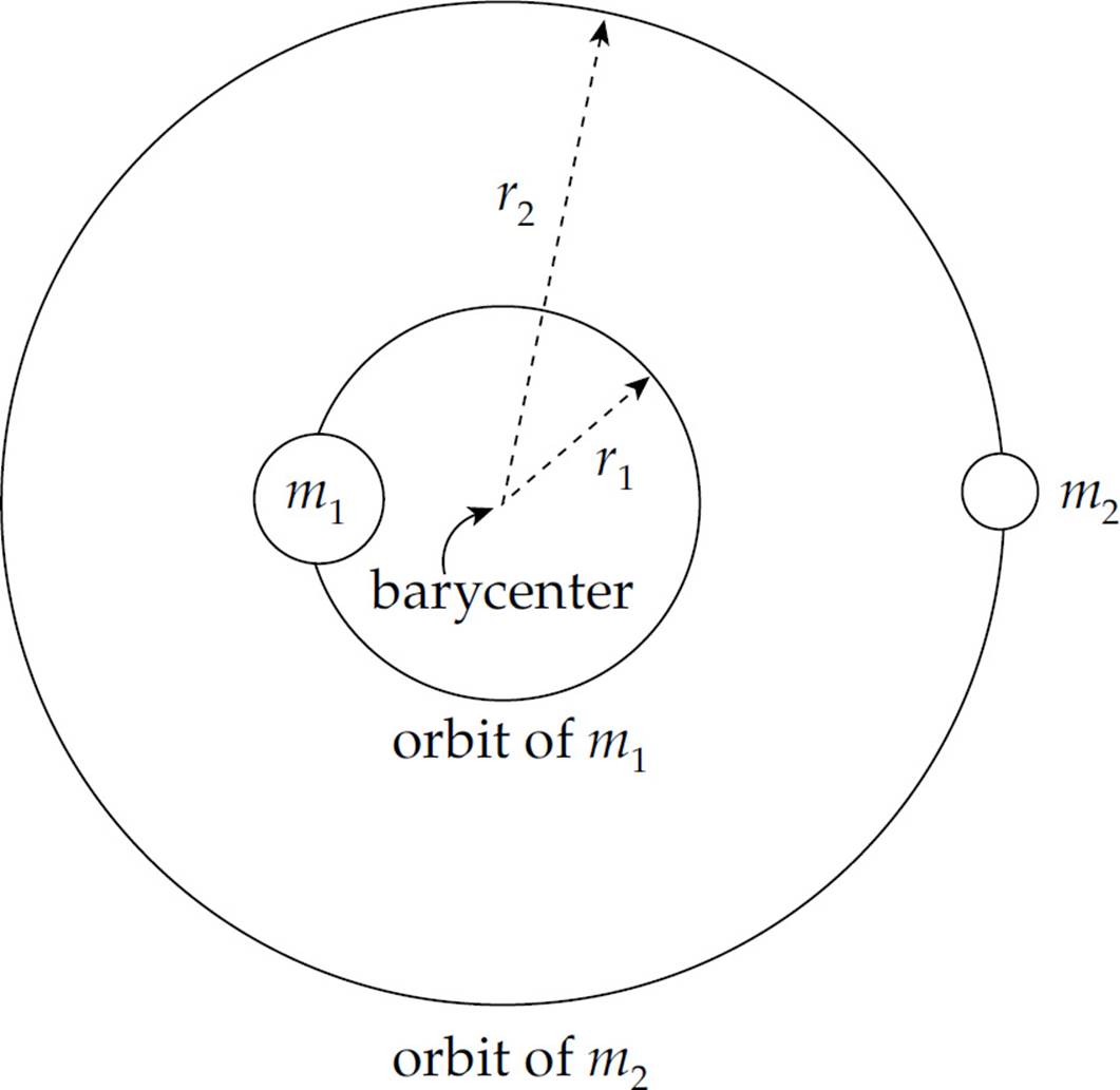
Therefore,
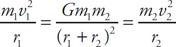
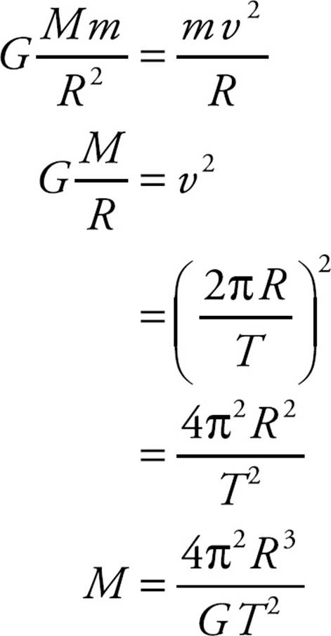
Since both spheres have the same orbit period, T, we get

We can also derive (as we did in Chapter 9, Example 9), that
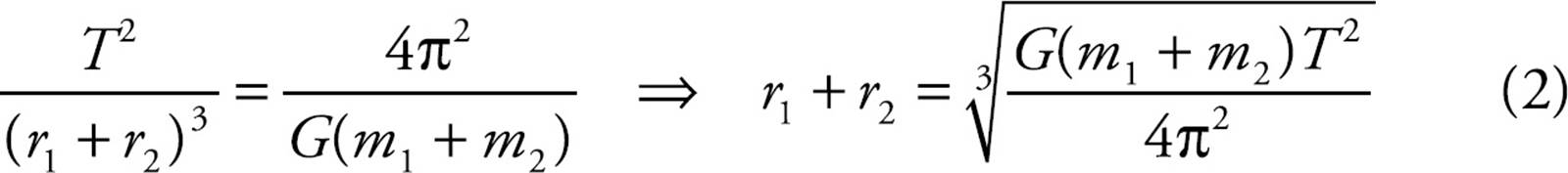
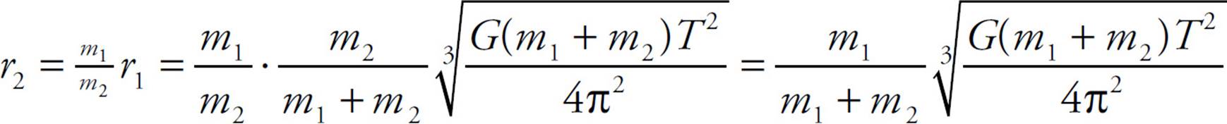
Substituting the result of Equation (1), r2 = (m1/m2)r1, into Equation (2), we can solve for r1:
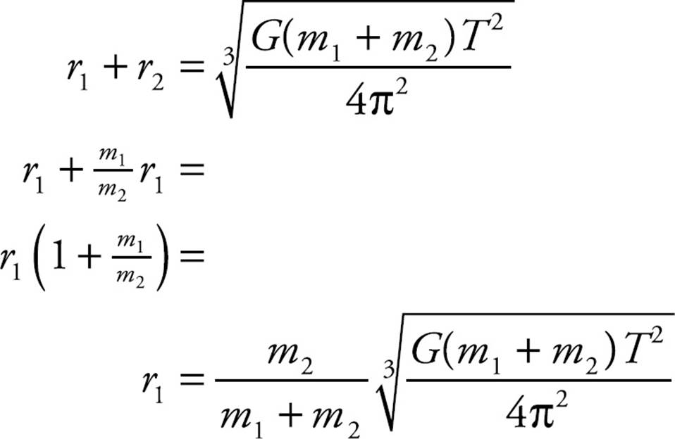
and then for r2:
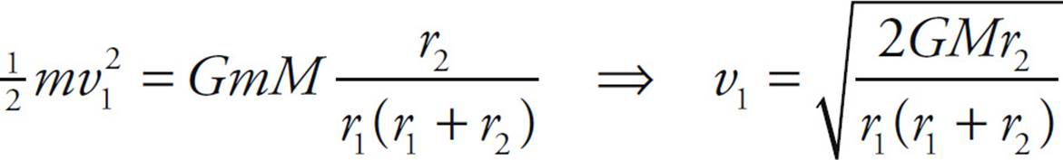
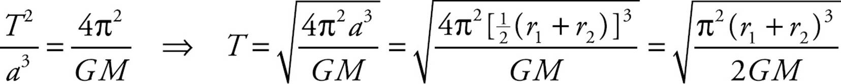
2. (a) The total energy of a satellite of mass m in an elliptical orbit with semimajor axis a around a planet of mass M is given by the equation E = –GmM/2a. From the figure, we see that 2a = r1 + r2, so the satellite’s kinetic energy at perigee is

Its speed at this point is then calculated as follows:
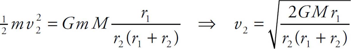
(b) Employing the same method as used in part (a), we find

so
(c) The ratio of v1 to v2 is
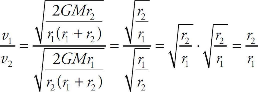
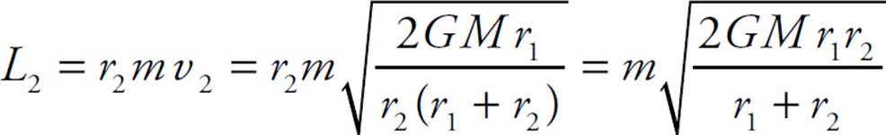
(d) Since v2 is perpendicular to r2, the satellite’s angular momentum is
(e) The distance from X to the center of Earth is equal to the semimajor axis, a = ![]() (r1 + r2). (This is because the sum of the distances from any point on the ellipse to the two foci must equal 2a = r1 + r2, and X is equidistant from the two foci, one of which is at the center of Earth.) Therefore, the kinetic energy of the satellite when it’s at X is
(r1 + r2). (This is because the sum of the distances from any point on the ellipse to the two foci must equal 2a = r1 + r2, and X is equidistant from the two foci, one of which is at the center of Earth.) Therefore, the kinetic energy of the satellite when it’s at X is
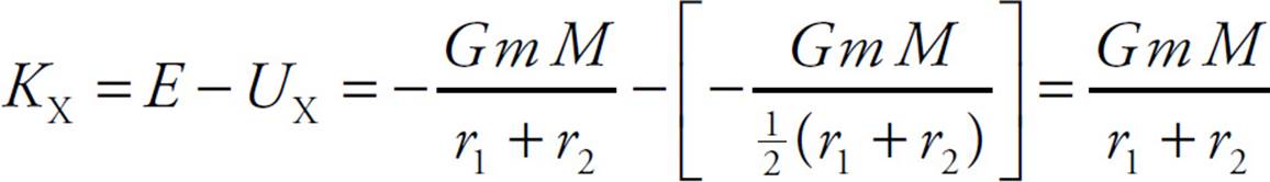
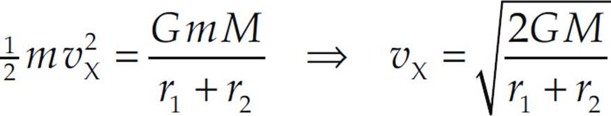
so its speed at this point can be determined:
(f) [See Example 8(c)] Use Kepler’s Third Law for elliptical orbits:
CHAPTER 10 REVIEW QUESTIONS
Section I: Multiple Choice
1. D The acceleration of a simple harmonic oscillator is not constant, since the restoring force—and, consequently, the acceleration—depends on position. Therefore Statement I is false. However, both Statements II and III are fundamental, defining characteristics of simple harmonic motion.
2. C The acceleration of the block has its maximum magnitude at the points where its displacement from equilibrium has the maximum magnitude (since a = F/m = kx/m). At the endpoints of the oscillation region, the potential energy is maximized and the kinetic energy (and hence the speed) is zero.
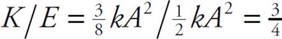
3. E Due to Conservation of Mechanical Energy, K + US is a constant for the motion of the block. At the endpoints of the oscillation region, the block’s displacement, x, is equal to ±A. Since K = 0 here, all the energy is in the form of potential energy of the spring, ![]() kA2. Because
kA2. Because ![]() kA2 gives the total energy at these positions, it also gives the total energy at any other position.
kA2 gives the total energy at these positions, it also gives the total energy at any other position.
Using the equation US(x) = ![]() kx2, we find that, at x =
kx2, we find that, at x = ![]() A,
A,
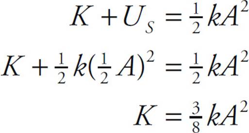
Therefore,
4. C As we derived in Chapter 10, Example 2, the maximum speed of the block is given by the equation vmax = 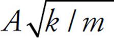 . Therefore, vmax is inversely proportional to
  . If m is increased by a factor of 2, then vmax will decrease by a factor of
  .
.
5. D The period of a spring–block simple harmonic oscillator is independent of the value of g. (Recall that T = 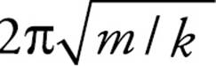 ) Therefore, the period will remain the same.
6. D The frequency of a spring–block simple harmonic oscillator is given by the equation f = 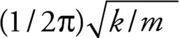 . Squaring both sides of this equation, we get f 2 = (k / 4π2)(1 / m). Therefore, if f 2 is plotted vs. (1/m), then the graph will be a straight line with slope k/4π2. (Note: The slope of the line whose equation is y = ax is a.)
7. A First we find the angular frequency:
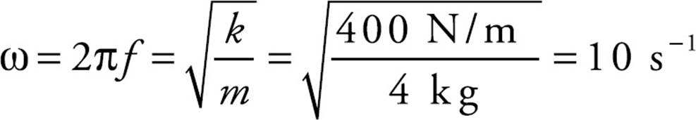
Therefore, the equation that gives the block’s position, x = A sin (ωt + φ0), becomes x = 6 sin (10t + φ0). Because the block is at x = 6 cm at time t = 0, the initial phase angle φ0 must be ![]() π.
π.
8. A Starting with the equation x = A sin(ωt + φ0), we differentiate with respect to t to find the velocity function: v = ẋ = Aω cos(ωt + φ0). Since the maximum value of cos(ωt + φ0) is 1, the maximum value of v is vmax = Aω.
9. C For small angular displacements, the period of a simple pendulum is essentially independent of amplitude.
10. B First draw a free-body diagram:
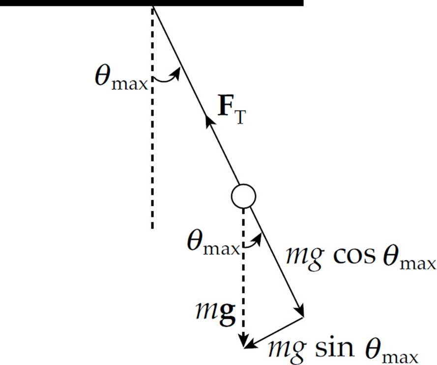
The net force toward the center of the bob’s circular path is FT – mg cos θmax. This must provide the centripetal force, mv2/L. But since the speed of the bob at this moment is zero (v = 0), we get FT = mg cos θmax. The acceleration is purely tangential here, equal to (mg sin θmax)/m = g sin θmax.
Section II: Free Response
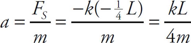
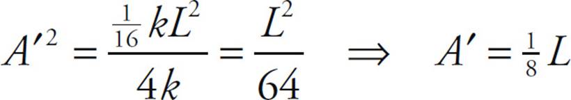
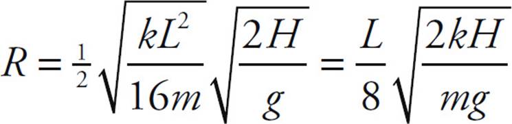
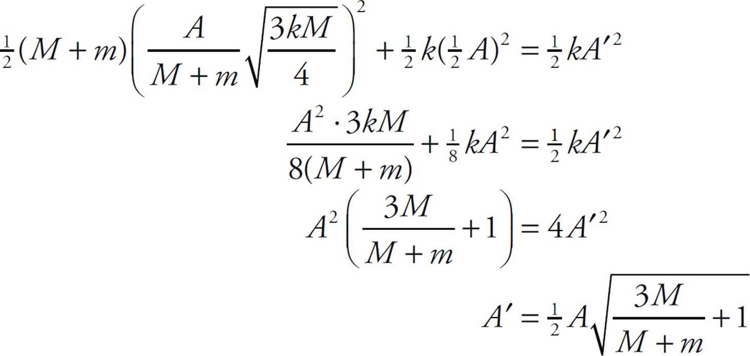
1. (a) Since the spring is compressed to ![]() its natural length, the block’s position relative to equilibrium is x = -
its natural length, the block’s position relative to equilibrium is x = -![]() L. Therefore, from FS = –kx, we find
L. Therefore, from FS = –kx, we find
(b) Let v1 denote the velocity of Block 1 just before impact, and let v′1 and v′2 denote, respectively, the velocities of Block 1 and Block 2 immediately after impact. By Conservation of Linear Momentum, we write mv1 = mv′1 + mv′2, or
v1 = v′1 + v′2 (1)
The initial kinetic energy of Block 1 is 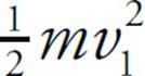 . If half is lost to heat, then
 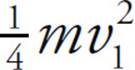 is left to be shared by Block 1 and Block 2 after impact:
 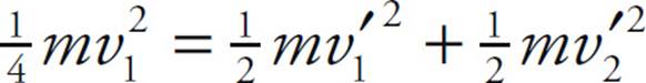 , or
, or
v21 = 2v′21 + 2v′22 (1)
Square Equation (1) and multiply by 2 to give
2v12 = 2v′12 + 4v′1v′2 + 2v′22 (1′)
then subtract Equation (2) from Equation (1′):
v12 = 4v′1v′2 (3)
Square Equation (1) again,
and substitute into this the result of Equation (3).
Thus, combining Equations (1) and (4), we find that
v′1 = v′2 = ![]() v1
v1
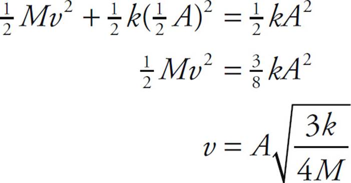
(c) When Block 1 reaches its new amplitude position, A′, all of its kinetic energy is converted to elastic potential energy of the spring. That is,
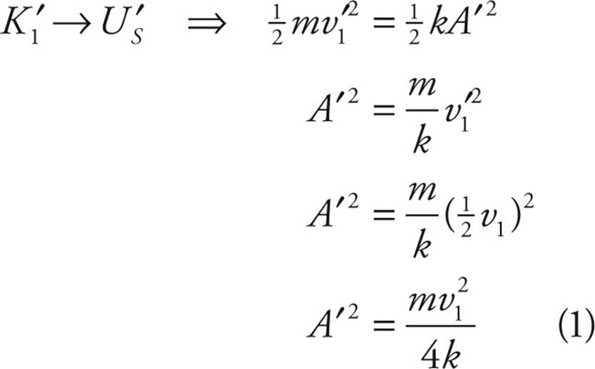
But the original potential energy of the spring, 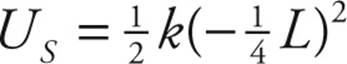 , gave K1 as

Substituting this result into Equation (1) gives
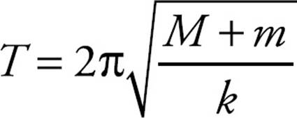
(d) The period of a spring–block simple harmonic oscillator depends only on the spring constant k and the mass of the block. Since neither of these changes, the period will remain the same; that is, T′ = T0.
(e) As we showed in part (b), Block 2’s velocity as it slides off the table is ![]() v1 (horizontally). The time required to drop the vertical distance H is found as follows (calling down the positive direction):
v1 (horizontally). The time required to drop the vertical distance H is found as follows (calling down the positive direction):
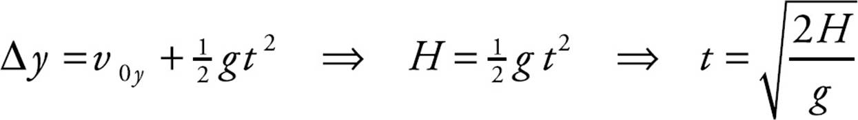
Therefore,
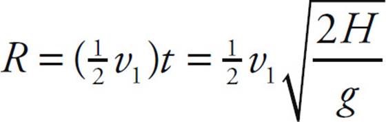
Now, from Equation (2) of part (c), v1 = 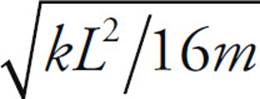 , so
, so
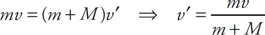
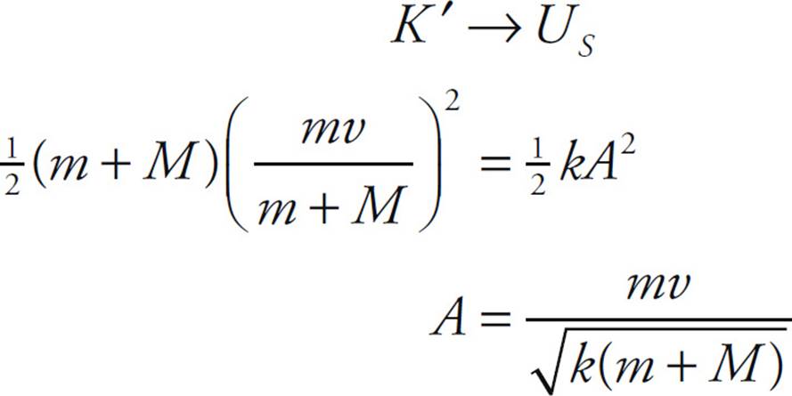
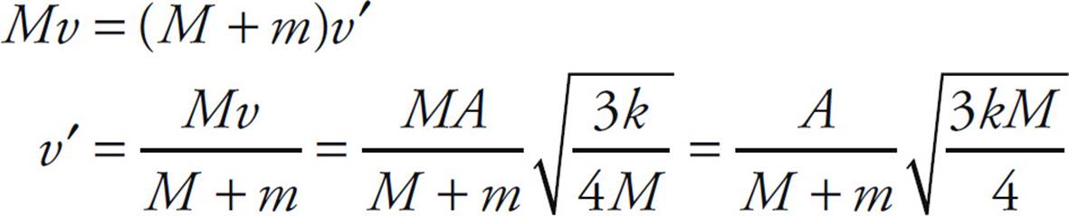
2. (a) By Conservation of Linear Momentum,
(b) When the block is at its amplitude position (maximum compression of spring), the kinetic energy it (and the embedded bullet) had just after impact will become the potential energy of the spring
(c) Since the mass on the spring is m + M, f = 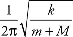 .
.
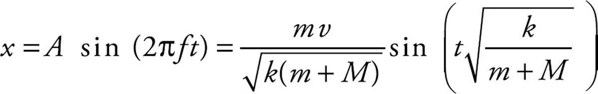
(d) The position of the block is given by the equation x = A sin(ωt + φ0), where ω = 2πf and A is the amplitude. Since x = 0 at time t = 0, the initial phase, φ0, is 0. From the results of parts (b) and (c), we have
3. (a) By Conservation of Mechanical Energy, K + U = E, so
(b) Since the clay ball delivers no horizontal linear momentum to the block, horizontal linear momentum is conserved. Thus,
(c) Applying the general equation for the period of a spring–block simple harmonic oscillator,
(d) The total energy of the oscillator after the clay hits is ![]() kA′2, where A′ is the new amplitude. Just after the clay hits the block, the total energy is
kA′2, where A′ is the new amplitude. Just after the clay hits the block, the total energy is

Substitute for v′ from part (b), set the resulting sum equal to ![]() kA′2, and solve for A′:
kA′2, and solve for A′:
(e) No, since the period depends only on the mass and the spring constant k.
(f) Yes. For example, if the clay had landed when the block was at x = A, the speed of the block would have been zero immediately before the collision and immediately after. No change in the block’s speed would have meant no change in K, so no change in E, so no change in A = 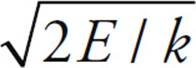 .
.
4. (a) Since the weight provides a clockwise torque (which is negative), we have τ = –dMg sin θ.
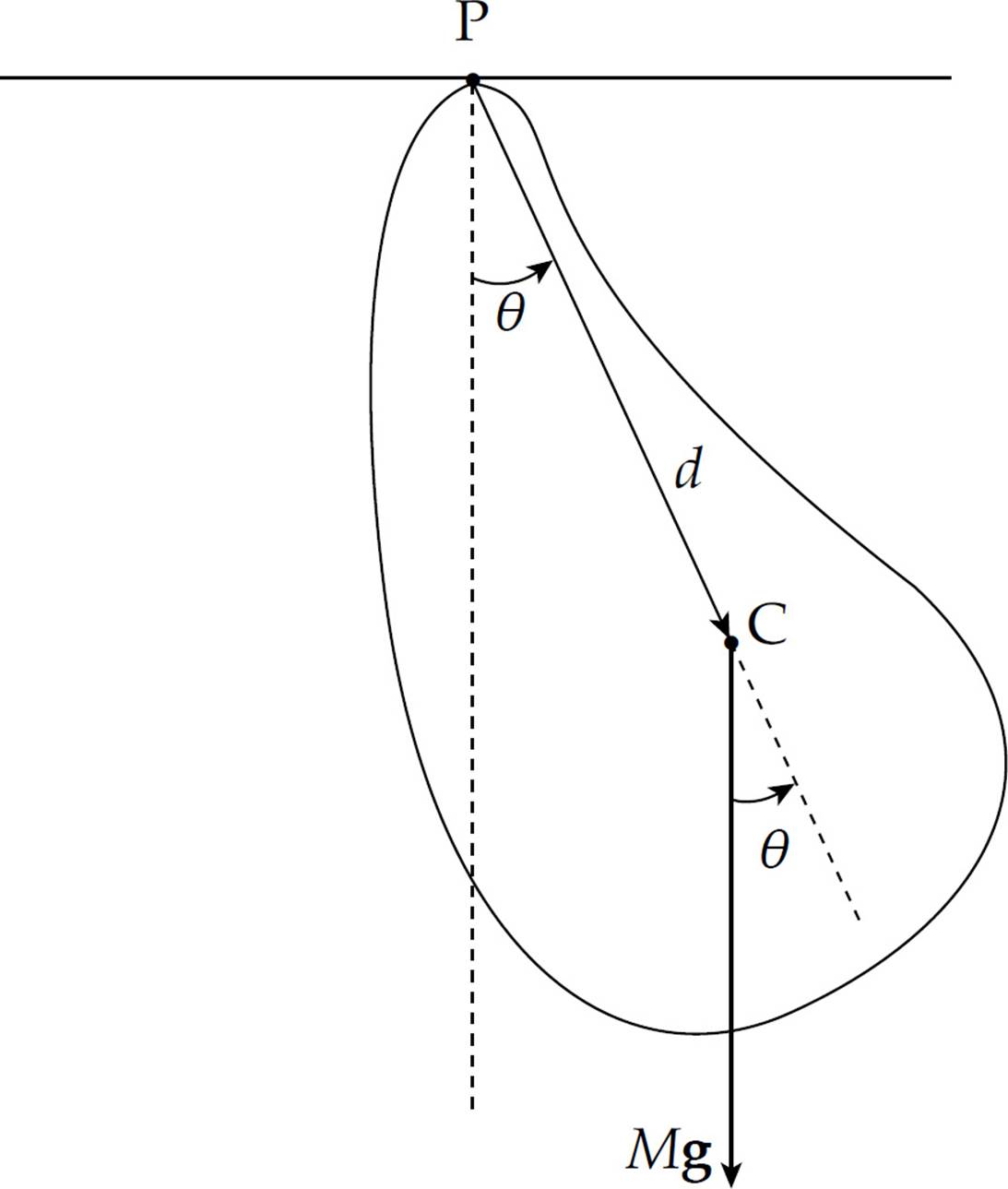
(b) If sin θ ≈ θ, then the equation in part (a) becomes
τ = –dMgθ (1)
(c) Since τ = Iα, Equation (1) implies Iα = −d mg θ. But by definition, α = d2θ/dt2, so we get
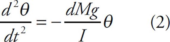
Equation (2) is identical to Equation (*) given in the statement of the question with z = θ and b = dMg/I. Therefore,
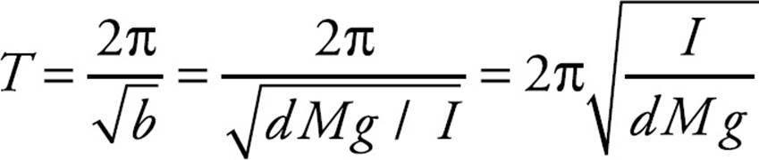
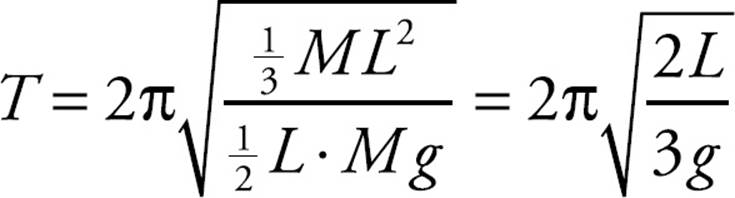
(d) Using the result of part (c) with I = ![]() ML2 and d =
ML2 and d = ![]() L, we get
L, we get
CHAPTER 11 REVIEW QUESTIONS
Section I: Multiple Choice
1. D Electrostatic force obeys an inverse-square law: FE ![]() 1/r2. Therefore, if r increases by a factor of 3, then FE decreases by a factor of 32 = 9.
1/r2. Therefore, if r increases by a factor of 3, then FE decreases by a factor of 32 = 9.
2. C The strength of the electric force is given by kq2/r2, and the strength of the gravitational force is Gm2/r2. Since both of these quantities have r2 in the denominator, we simply need to compare the numerical values of kq2 and Gm2. There’s no contest: Since
kq2 = (9 × 10⁹ N·m2/C2)(1 C)2 = 9 × 10⁹ N·m2
and
Gm2 = (6.7 × 10⁻¹¹ N·m2/kg2)(1 kg)2 = 6.7 × 10⁻¹¹ N·m2
we see that kq2 >> Gm2, so FE is much stronger than FG.
3. C If the net electric force on the center charge is zero, the electrical repulsion by the +2q charge must balance the electrical repulsion by the +3q charge:

4. E Since P is equidistant from the two charges, and the magnitudes of the charges are identical, the strength of the electric field at P due to +Q is the same as the strength of the electric field at P due to –Q. The electric field vector at P due to +Q points away from +Q, and the electric field vector at P due to –Q points toward –Q. Since these vectors point in the same direction, the net electric field at P is (E to the right) + (E to the right) = (2E to the right).
5. D The acceleration of the small sphere is
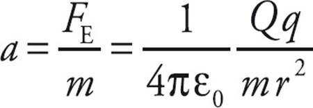
As r increases (that is, as the small sphere is pushed away), a decreases. However, since a is always positive, the small sphere’s speed, v, is always increasing.
6. B Since FE (on q) = qE, it must be true that FE (on –2q) = –2qE = –2FE.
7. D All excess electric charge on a conductor resides on the outer surface.
8. B The net electric flux through the Gaussian surface, ΦE, is equal to (1/ε0) times the net charge enclosed by the surface, Q2 + Q3. However, the net electric field vector at P is equal to the sum of the electric field vectors due to each of the four charges individually.
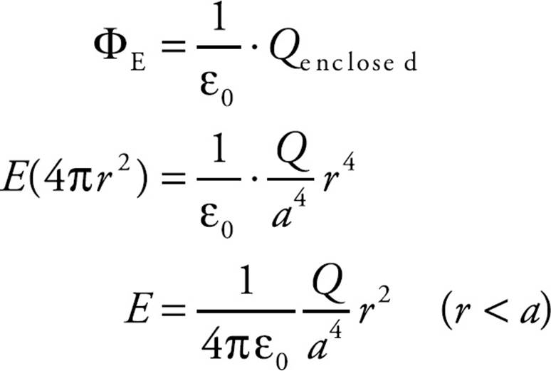
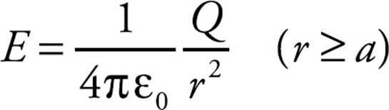
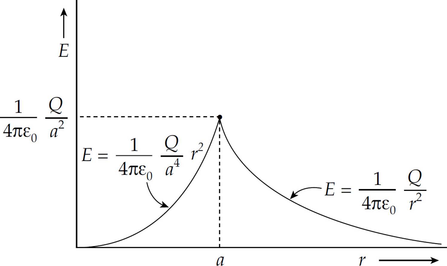
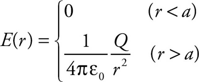
9. A Since the charge is distributed uniformly throughout the sphere, the magnitude of its volume charge density is ρ = Q/ . Therefore, if we construct a spherical Gaussian surface of radius r < R, Gauss’s Law gives

Since the charge on the sphere is negative, the direction of E at any point is directed radially inward.
10. A By definition, an electric dipole consists of two equal but opposite charges. Therefore a Gaussian surface enclosing both charges would enclose zero net charge. By Gauss’s Law, the electric flux is zero as well (since ΦE = Qenclosed/ε0).
Section II: Free Response
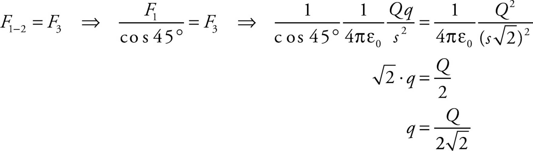
1. (a) From the figure below, we have F1-2 = F1/cos 45°.
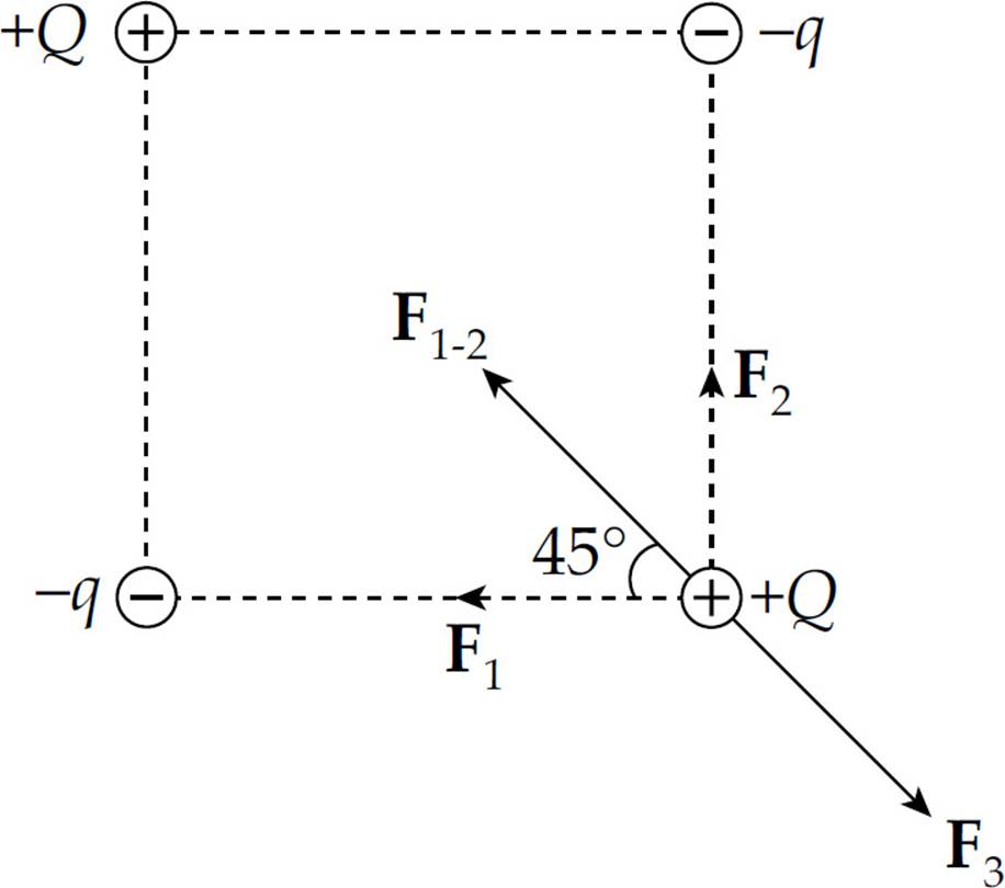
Since the net force on +Q is zero, we want F1-2 = F3. If s is the length of each side of the square, then:
(b) No. If q = Q/2 , as found in part (a), then the net force on –q is not zero.
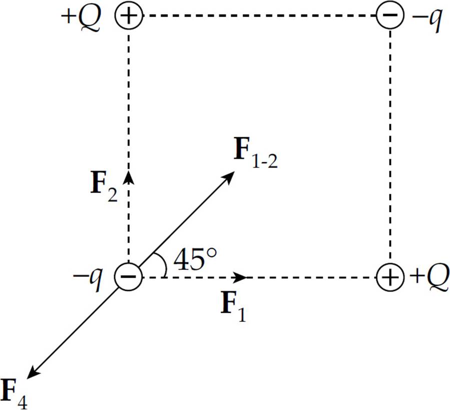
This is because F1-2 ≠ F4, as the following calculations show:
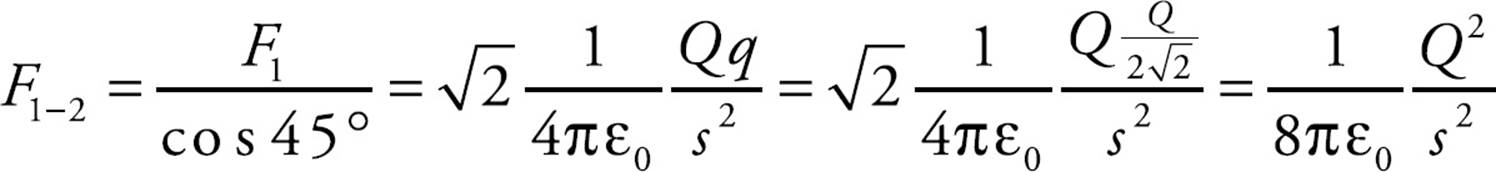
but
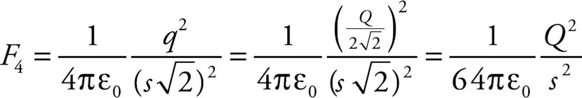
(c) By symmetry, E1 = E2 and E3 = E4, so the net electric field at the center of the square is zero:
2. (a) The magnitude of the electric force on Charge 1 is
The direction of F1 is directly away from Charge 2; that is, in the +y direction, so
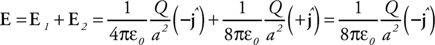
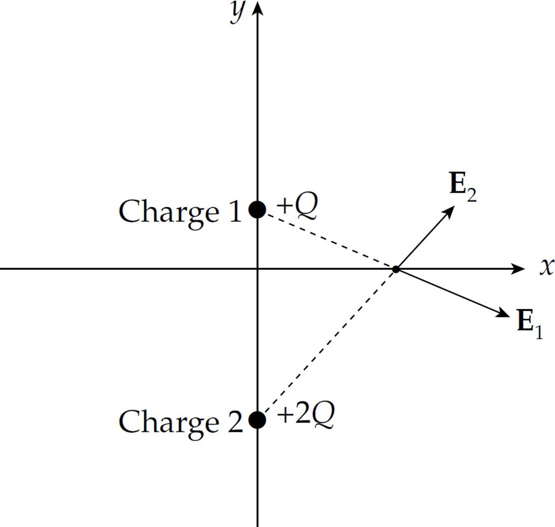
(b) The electric field vectors at the origin due to Charge 1 and due to Charge 2 are

Therefore, the net electric field at the origin is
(c) No. At no point on the x-axis will the individual electric field vectors point in exactly opposite directions.
Therefore, at no point on the x-axis could the total electric field be zero.
(d) Yes. There will be a Point P on the y-axis between the two charges, where the electric fields due to the individual charges will cancel each other out.
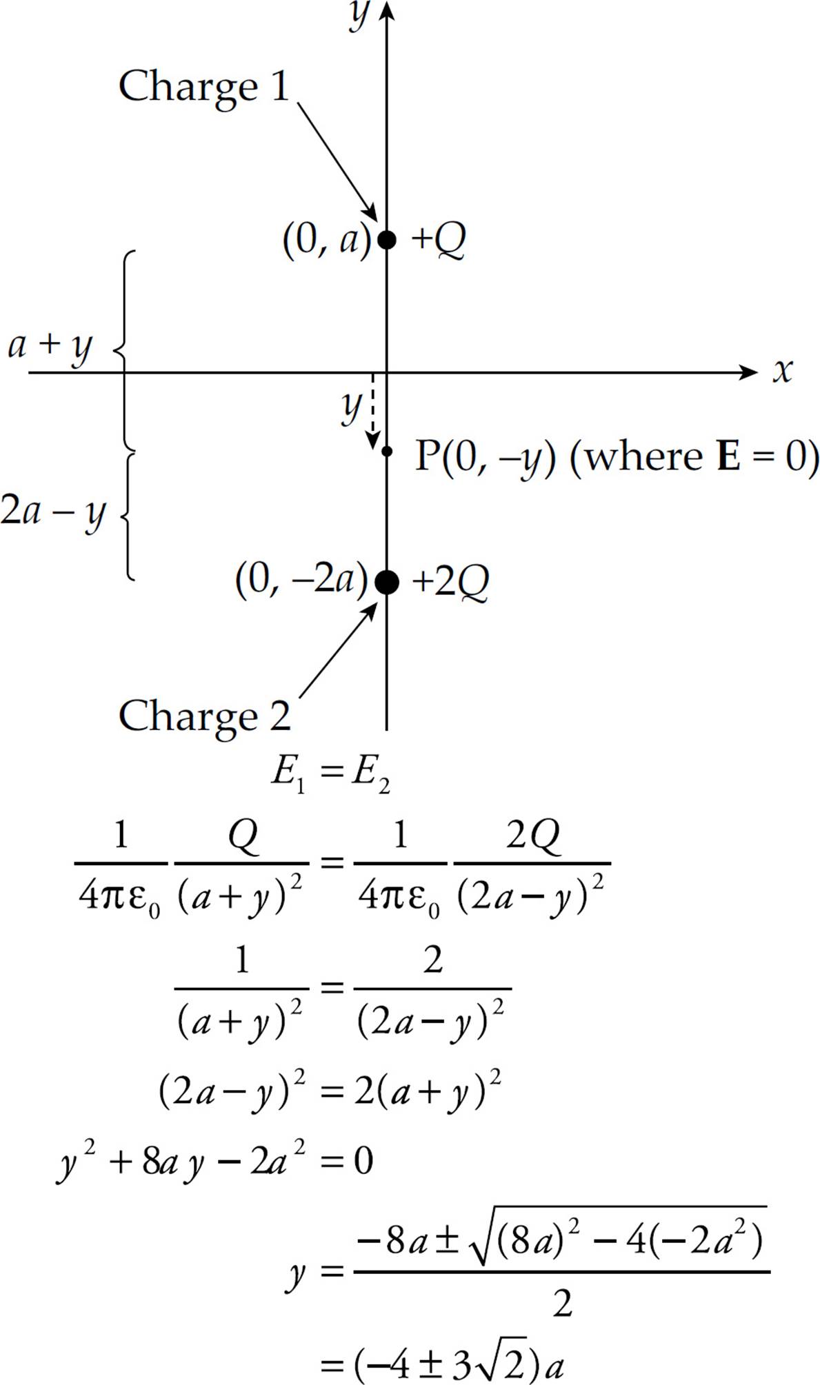
Disregarding the value y = 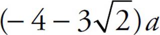 (because it would place the point P below Charge 2 on the y-axis, where the electric field vectors do not point in opposite directions), we have that E = 0 at the point P = (0, –y) = (0,
  ).
).
(e) Use the result of part (b) with Newton’s Second Law:
3. (a) The charges on the surfaces of the shells will be distributed as follows:
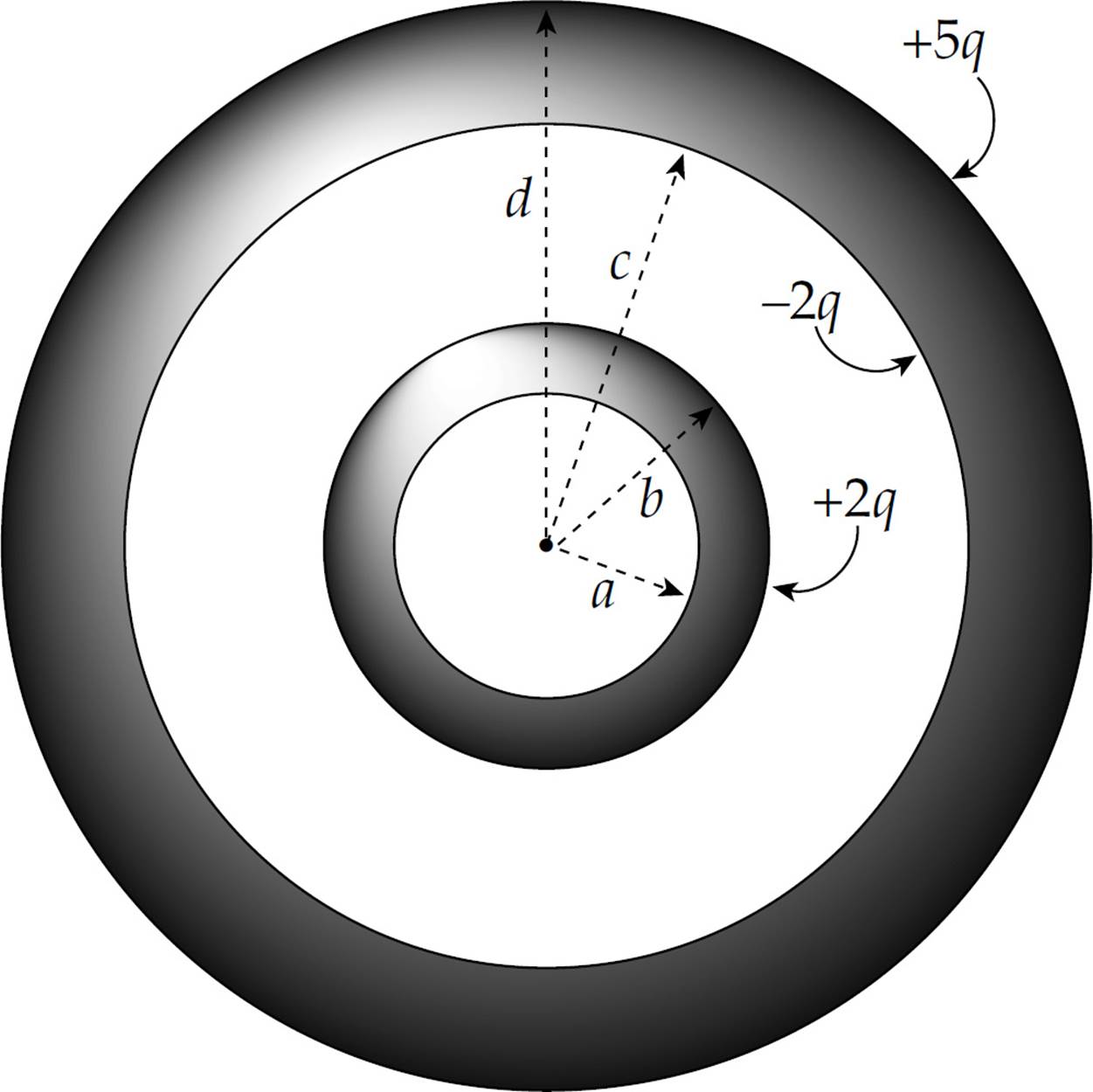
Therefore, by Gauss’s Law, the electric field in the various regions are as follows:
|
(i) |
r < a |
E = 0 (no charge inside) |
|
(ii) |
a < r < b |
E = 0 (within metallic shell) |
|
(iii) |
b < r < c |
E = (1 / 4πε0)(2q / r2) |
|
(iv) |
c < r < d |
E = 0 (within metallic shell) |
|
(v) |
r > d |
E = (1 / 4πε0)(5q / r2) |
(b) Within each metallic shell, there is no excess charge. The inner surface of the inner shell also has no excess charge. See the figure above for part (a) for the charges residing on the other surfaces of the shells.
4. (a) Very close to the rod, the rod behaves as if it were “infinitely long.” Construct a cylindrical Gaussian surface of radius x1 and length L centered on the rod. By symmetry the electric field at P1 must point radially away from the rod, so the field at P1 must point in the positive x direction.
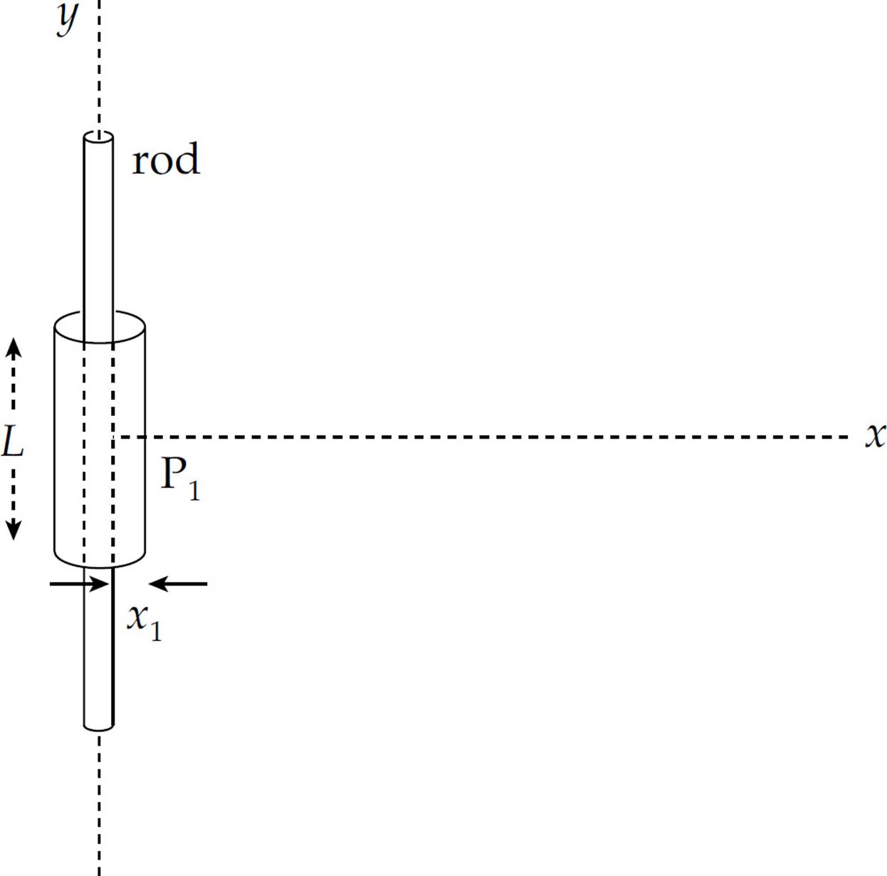
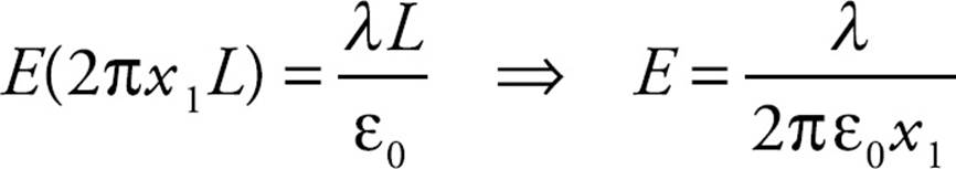
There is no electric flux through the ends of the cylinder (since E is parallel to the lids of the cylinder); the electric flux is perpendicular to the lateral surface area of the cylinder, so ΦE = 0 + E A + 0 = E(2πx1L). Since the charge enclosed by the surface is λL, Gauss’s Law gives
(b) The total charge on the rod is equal to its linear charge density times its total length: Q = λ![]() .
.
(c) If x2 is not small compared to ![]() , then we must calculate the electric field at P2 by integration. Consider two symmetrically located line elements along the rod, each of length dy, at a distance y above and below the origin.
, then we must calculate the electric field at P2 by integration. Consider two symmetrically located line elements along the rod, each of length dy, at a distance y above and below the origin.
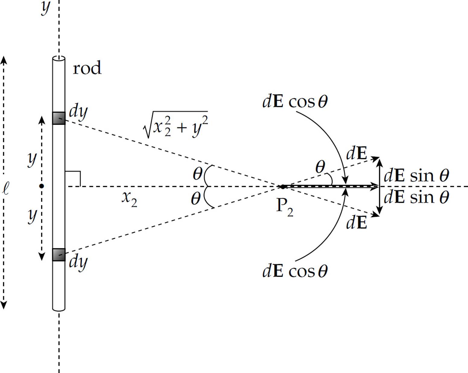
The vertical components of the electric fields at P2 will cancel (by symmetry), leaving the net electric field at P2 due to this pair of line elements equal to the sum of the horizontal components. Therefore,
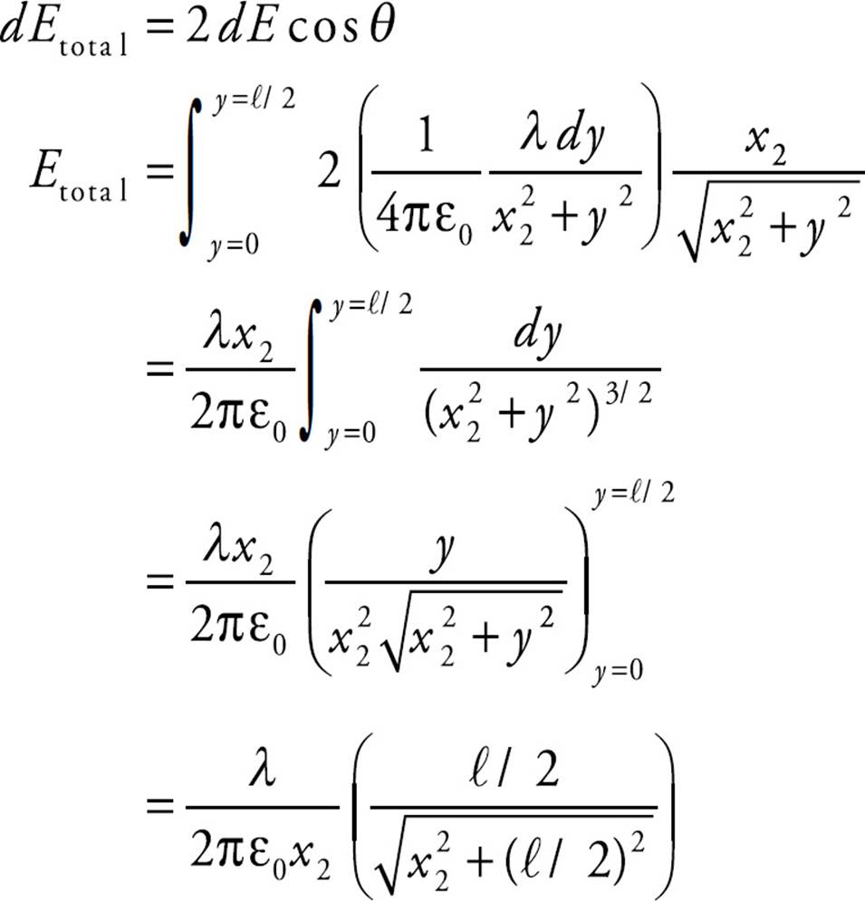
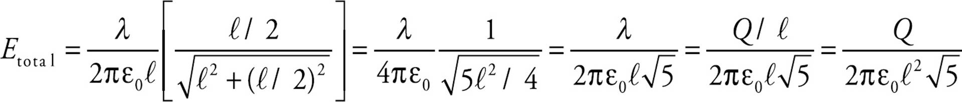
If x2 = ![]() , then
, then
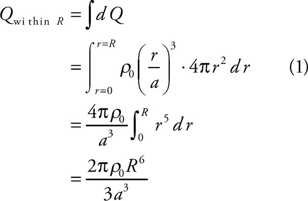
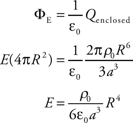
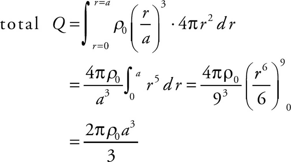
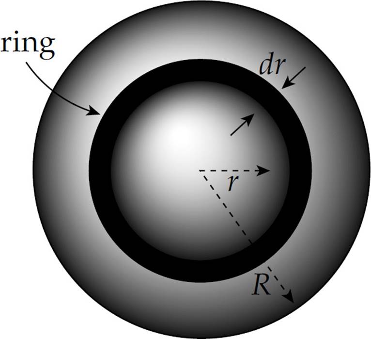
5. (a) Volume charge density has units of charge per unit volume, that is, [ρ] = C/m3. Since r/a has no units, ρs must also have units of C/m3.
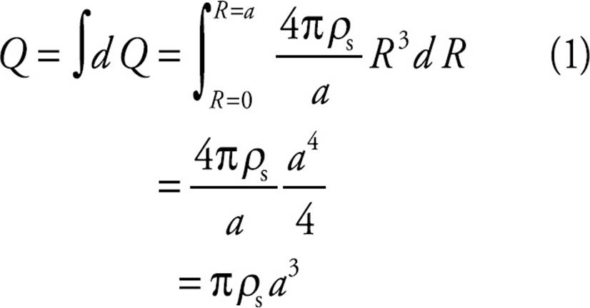
(b) Since ρ varies with the distance from the center, consider a thin spherical shell of radius R and thickness dR. Its volume is dV = 4πR2 dR, so its charge is
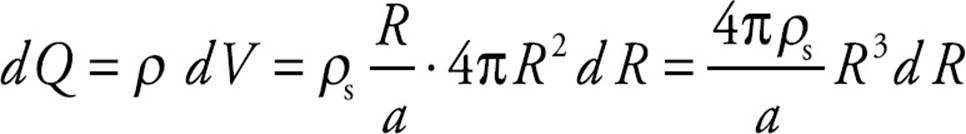
The charge on the entire sphere is found by integrating dQ from R = 0 to R = a:
(c) (i) Replace “R = a” with “R = r” in Equation (1) above to find the charge enclosed by a spherical Gaussian surface of radius r < a:
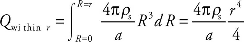
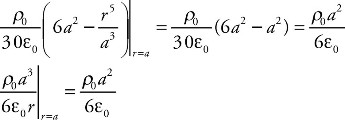
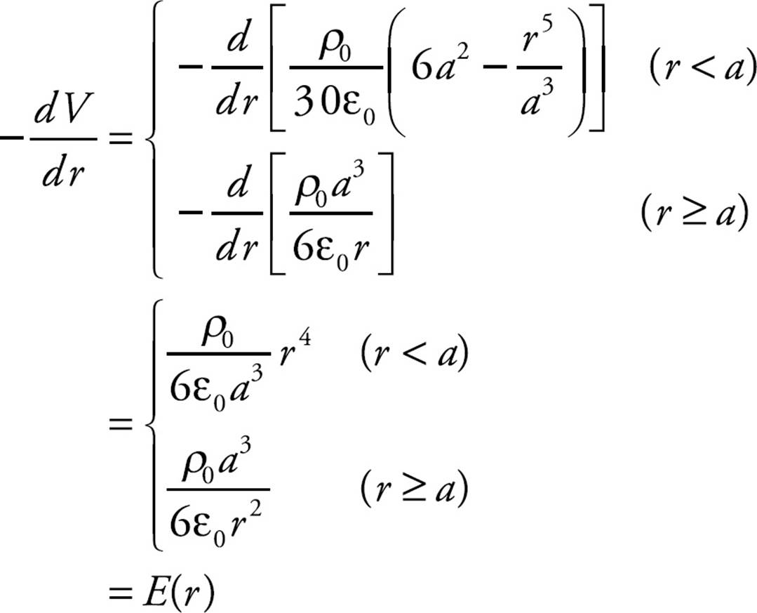
Using the result of part (b), we can write this expression for Qwithin r in terms of Q, the total charge on the full sphere:
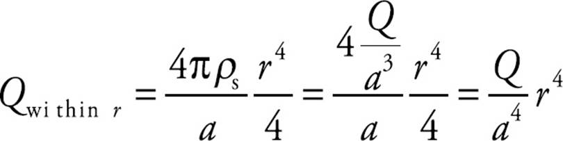
So, by Gauss’s Law,
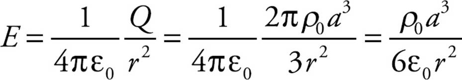
(c) (ii) Outside the sphere, Qenclosed = Q, so
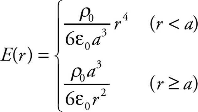
(d)
CHAPTER 12 REVIEW QUESTIONS
Section I: Multiple Choice
1. E A counterexample for Statement I is provided by two equal positive charges; at the point midway between the charges, the electric field is zero, but the potential is not. A counterexample for Statement II is provided by an electric dipole (a pair of equal but opposite charges); at the point midway between the charges, the electric potential is zero, but the electric field is not. As for Statement III, consider a single positive point charge +Q. Then at a distance r from this source charge, the electric field strength is E = kQ/r2 and the potential is V = kQ/r. Thus, V = rE, so V is not inversely proportional to E.
2. C By definition,  UE = –WE, so if WE is negative, then
  UE is positive. This implies that the potential energy, UE, increases.
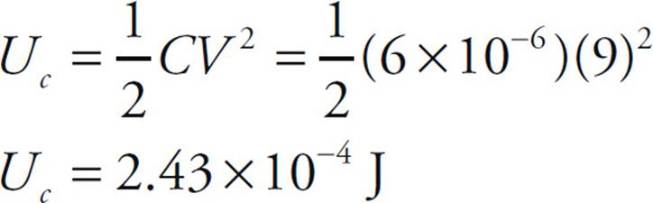
3. D You may be tempted to solve for the equivalent capacitance and then use that to determine the total charge stored on the capacitors, but we can already tell the potential difference across each capacitor is 9 V. The energy stored in a capacitor is given by the equation
4. B Use the definition V = –WE/q. If an electric field accelerates a negative charge doing positive work on it, then WE > 0. If q < 0, then –WE/q is positive. Therefore,  V is positive, which implies that V increases.
5. E By definition,
VA → B = UE/q, so VB – VA = UE/q
6. C Because E is uniform, the potential varies linearly with distance from either plate (V = Ed). Since Points 2 and 4 are at the same distance from the plates, they lie on the same equipotential. (The equipotentials in this case are planes parallel to the capacitor plates.)
7. D Once the spheres are connected by a conducting wire, they quickly form a single equipotential surface. Since the potential on a sphere of radius r carrying charge q is given by the equation (1/4πε0)(q/r), we have

Now, since q1 + q2 = –Q + –Q = –2Q, the fact that q1 must equal q2/4 means that (q2/4) + q2 = –2Q, which gives q2 = (–8/5)Q and q1 = (–2/5)Q.
8. A Since Q cannot change and C is increased (because of the dielectric), V = Q/C must decrease. Also, since UE = Q2/(2C), an increase in C with no change in Q implies a decrease in UE.
9. B By definition, WE = –qV, which gives
WE = −q(VB − VA) = −(−0.05 C)(100 V − 200 V)
Note that neither the length of the segment AB nor that of the curved path from A to B is relevant.
10. D
Capacitors 1 and 2 are in series, so their equivalent capacitance is C1-2 = C/2. (This is obtained from the equation 1/C1-2 = 1/C1 + 1/C2 = 1/C + 1/C = 2/C.) Capacitors 4 and 5 are also in series, so their equivalent capacitance is C4-5 = C/2. The capacitances C1-2, C3, and C4-5 are in parallel, so the overall equivalent capacitance is (C/2) + C+ (C/2) = 2C.
11. C Points A and E are on the same equipotential line, so no work is done by the field to move the electron from A to E. Electric fields go in the direction of decreasing potential, so the field associated with these equipotential lines is generally going to the left. The field lines indicate the force on a positive test charge, so the force on an electron will be in the opposite direction. Therefore, the work done by the field on the electron is negative for the movement from E to C because the force on the electron is to the right and the movement is to the left.
Section II: Free Response
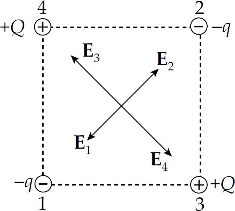
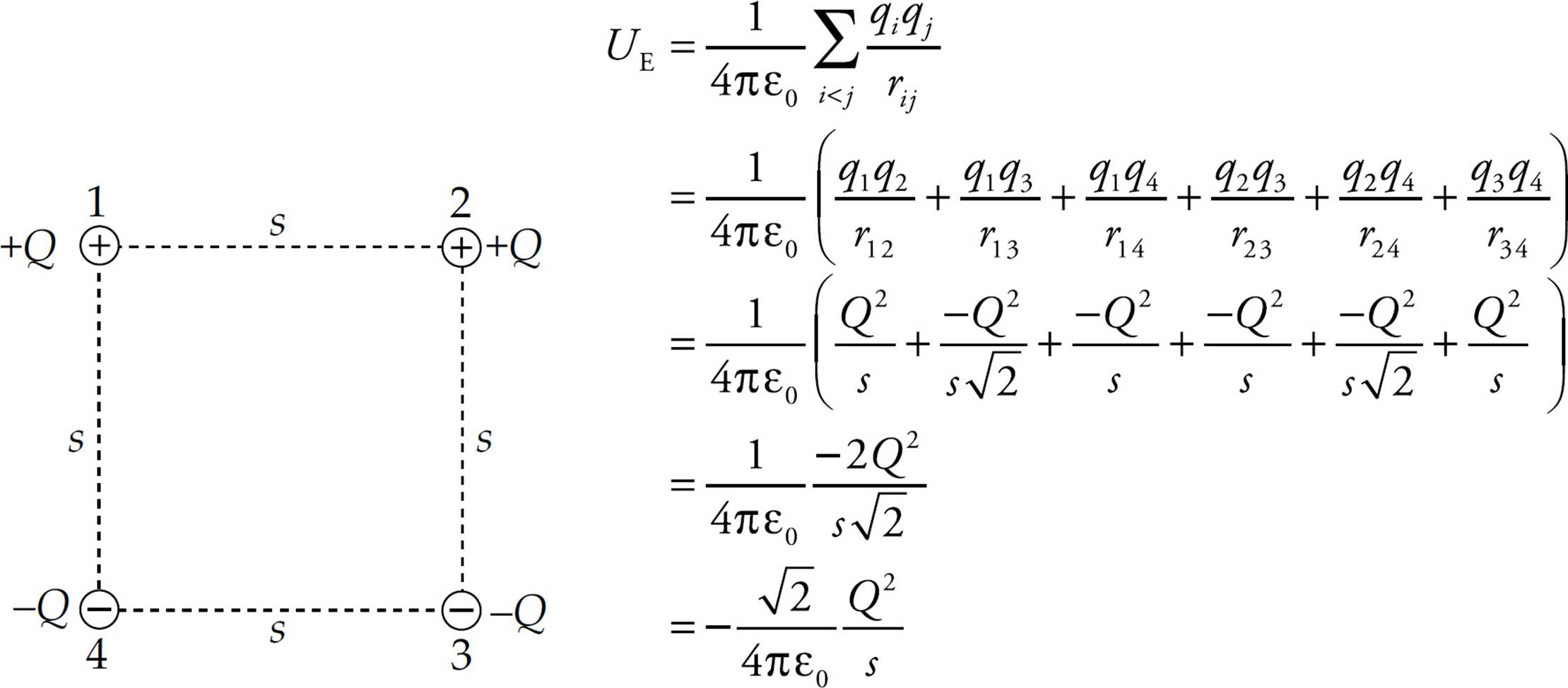
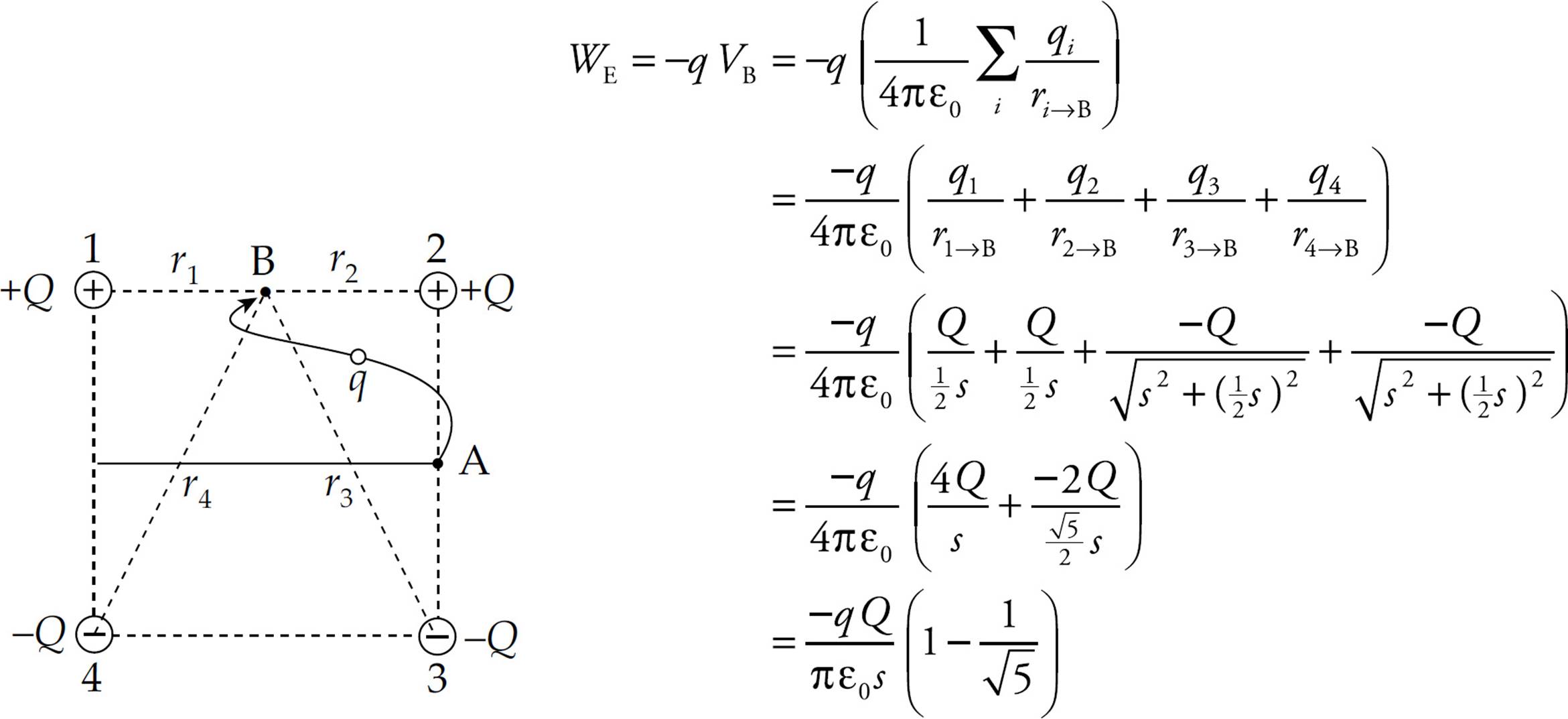
1. (a) Labeling the four charges as given in the diagram, we get
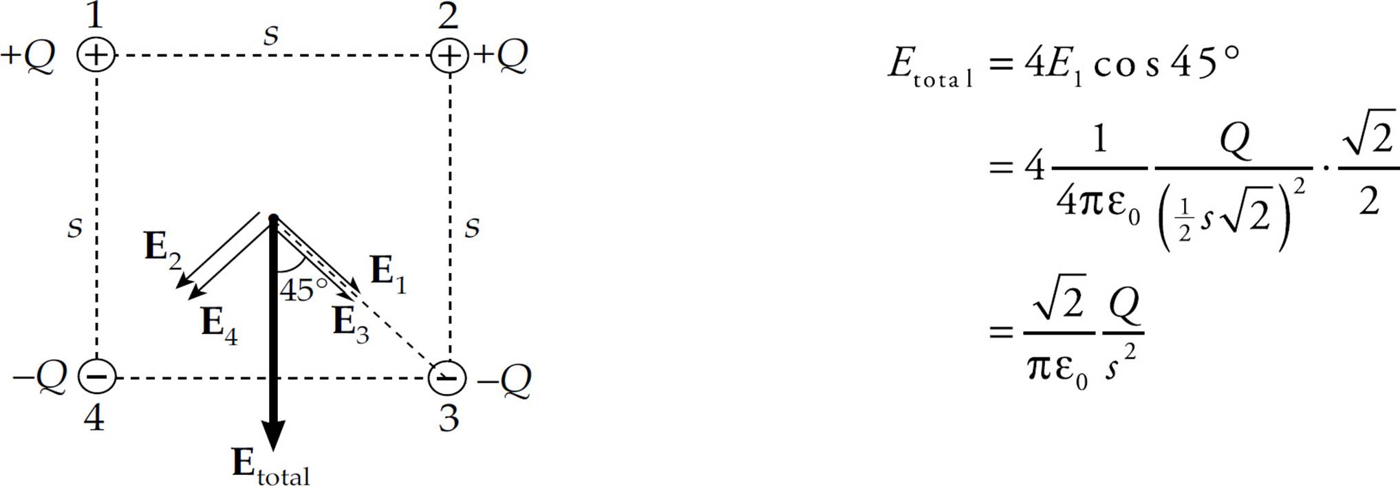
(b) Let Ei denote the electric field at the center of the square due to charge i. Then by symmetry, E1 = E3, E2 = E4, and E1 = E2 = E3 = E4. The horizontal components of the four individual field vectors cancel, leaving only a downward-pointing electric field of magnitude Etotal = 4E1 cos 45°:
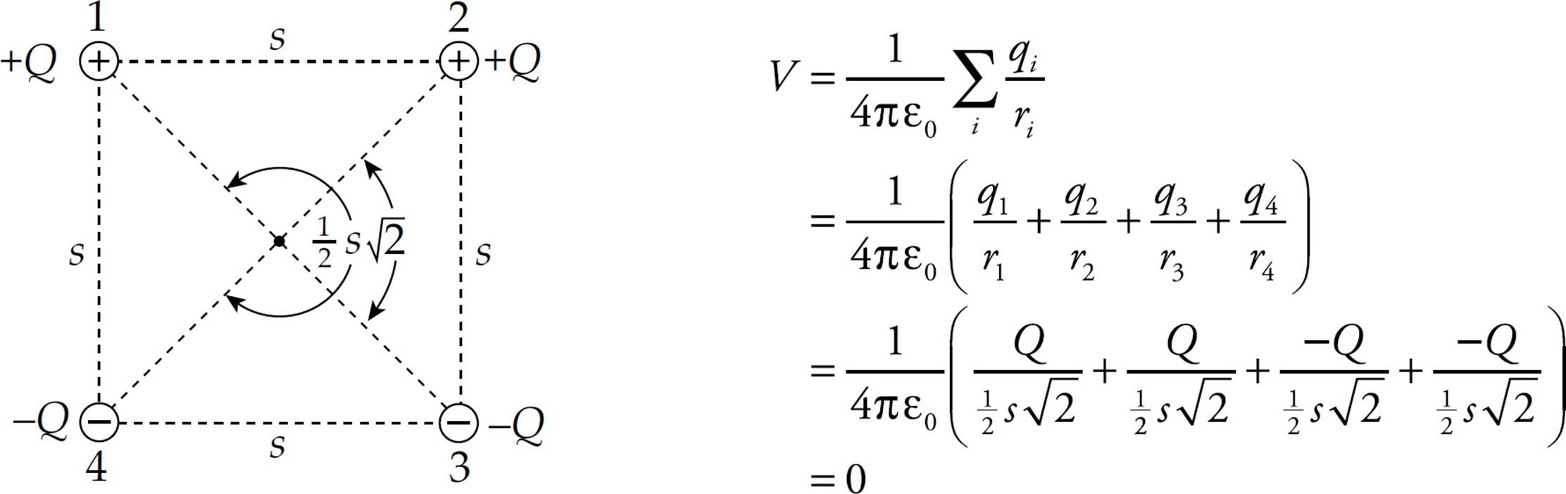
(c) The potential at the center of the square is zero:
(d) At every point on the center horizontal line shown, r1 = r4 and r2 = r3, so V will equal zero (just as it does at the center of the square):
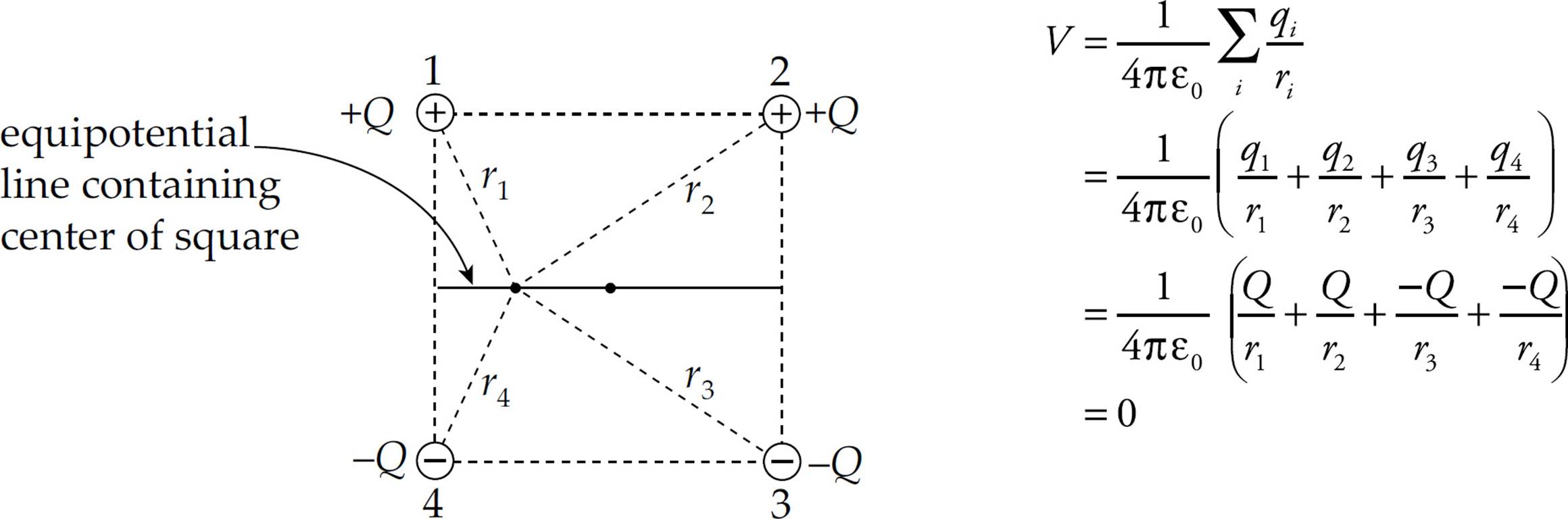
(e) The work done by the electric force as q is displaced from Point A to Point B is given by the equation WE = –q VA → B = –q(VB – VA) = –qVB (since VA = 0).
2. (a) The capacitance is C = ε0A/d. Since the plates are rectangular, the area A is equal to Lw, so C = ε0Lw/d.
(b) and (c) Since the electron is attracted upward, the top plate must be the positive plate.
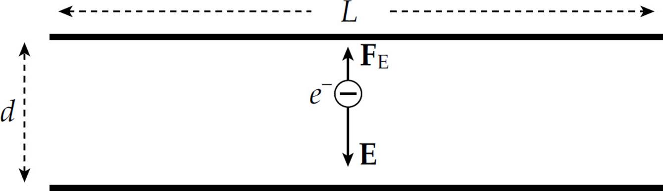
(d) The acceleration of the electron is a = FE/m = qE/m = eE/m, vertically upward. Therefore, applying Big Five #3 for vertical motion, y = v0yt + ![]() ayt2, we get
ayt2, we get
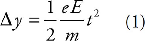
To find t, notice that v0x = v0 remains constant (because there is no horizontal acceleration). Therefore, the time necessary for the electron to travel the horizontal distance L is t = L/v0. In this time, y is d/2, so Equation (1) becomes
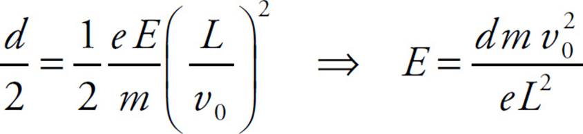
(e) Substituting the result of part (d) into the equation V = Ed gives
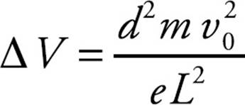
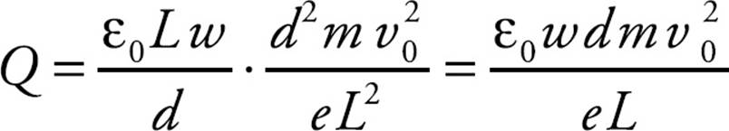
Since Q = CV (by definition), the result of part (a) now gives
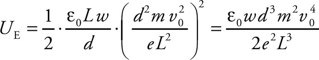
(f) Applying the equation UE = ![]() C(V)2, we get
C(V)2, we get
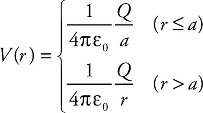
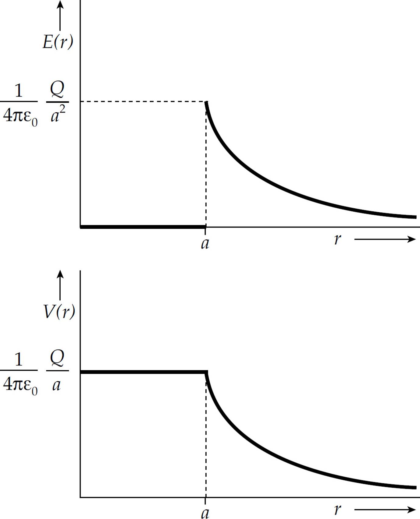
3. (a) Outside the sphere, the sphere behaves as if all the charge were concentrated at the center. Inside the sphere, the electrostatic field is zero:
(b) On the surface and outside the sphere, the electric potential is (1/4πε0)(Q/r). Within the sphere, V is constant (because E = 0) and equal to the value on the surface. Therefore,
(c) See diagrams:
4. (a) To find the electric field inside the sphere, construct a spherical Gaussian surface of radius R < a. We need to determine the charge enclosed by this sphere. Therefore, consider a thin spherical shell of radius r and thickness dr. The charge within this shell is dQ = ρ dV = ρ (4πr2 dr), so the total charge within a sphere of radius R is
For the Gaussian surface, Gauss’s Law then gives
Now, to find the electric field outside the sphere, we first determine the sphere’s total charge. Replacing r = R in Equation (1) by r = a gives
Thus, for points outside the sphere, the electric field is
In summary, then,
(b) We follow the same procedure used in Chapter 12, Example 14: The potential at some distance, let’s call it r0, from the center is equal to the negative of the work done by the electric field as a charge q is brought to r0 from infinity, divided by q. (By definition, V = UE/q = –WE/q, where we take V = 0 at infinity.) So, our first step (the big one) is to compute the work done by the electric field in bringing a charge q in from infinity to a point inside the sphere at a distance of r0 < a from the center:
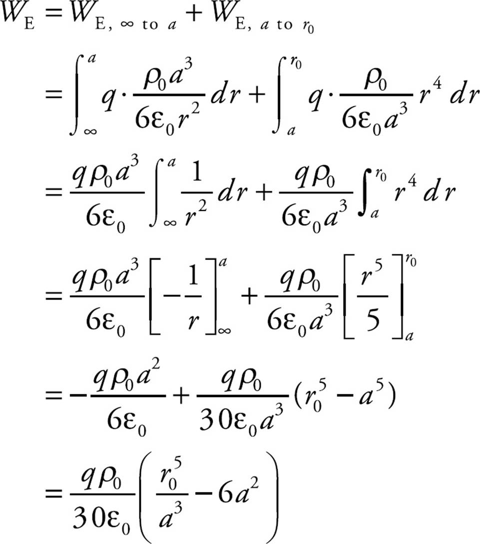
Taking the negative of this result, dividing by q, and replacing r0 by r gives our answer:
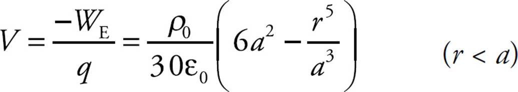
On the surface and outside the sphere, the potential is
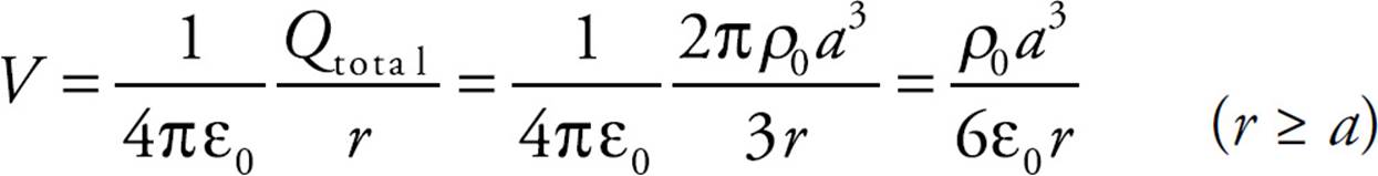
In summary,
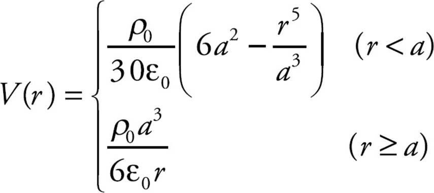
As a check on these formulas, we note first that the function V(r) is continuous (as it must always be); the only question about continuity is at r = a. But continuity here is assured because substituting r = a into either of the expressions for V(r) gives the same result:
Second, we can verify that E = –dV/dr:
(c) See the diagrams:
CHAPTER 13 REVIEW QUESTIONS
Section I: Multiple Choice
1. A Let ρS denote the resistivity of silver and let AS denote the cross-sectional area of the silver wire. Then
2. D The equation I = V/R implies that increasing V by a factor of 2 will cause I to increase by a factor of 2.
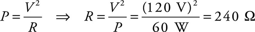
3. C Use the equation P = V 2/R.
4. B The current through the circuit is
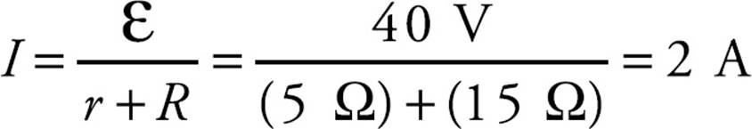
Therefore, the voltage drop across R is V = IR = (2 A)(15 Ω) = 30 V.
5. E The 12 Ω and 4 Ω resistors are in parallel and are equivalent to a single 3 Ω resistor, because 1/(12 Ω) + 1/(4 Ω) = 1/(3 Ω). This 3 Ω resistor is in series with the top 3 Ω resistor, giving an equivalent resistance in the top branch of 3 + 3 = 6 Ω. Finally, this 6 Ω resistor is in parallel with the bottom 3 Ω resistor, giving an overall equivalent resistance of 2 Ω, because 1/(6 Ω) + 1/(3 Ω) = 1/(2 Ω).
6. D If each of the identical bulbs has resistance R, then the current through each bulb is ε/R. This is unchanged if the middle branch is taken out of the parallel circuit. (What will change is the total amount of current provided by the battery.)
7. B The three parallel resistors are equivalent to a single 2 Ω resistor, because 1/(8 Ω) + 1/(4 Ω) + 1/(8 Ω) = 1/(2 Ω). This 2 Ω resistance is in series with the given 2 Ω resistor, so their equivalent resistance is 2 + 2 = 4 Ω. Therefore, three times as much current will flow through this equivalent 4 Ω resistance in the top branch as through the parallel 12 Ω resistor in the bottom branch, which implies that the current through the bottom branch is 3 A, and the current through the top branch is 9 A. The voltage drop across the 12 Ω resistor is therefore V = IR = (3 A)(12 Ω) = 36 V.
8. E Since points a and b are grounded, they’re at the same potential (call it zero).
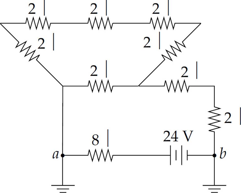
Traveling from b to a across the battery, the potential increases by 24 V, so it must decrease by 24 V across the 8 Ω resistor as we reach point a. Thus, I = V/R = (24 V)/(8 Ω) = 3 A.
9. D The equation P = I2R gives
P = (0.5 A)2(100 Ω) = 25 W = 25 J/s
Therefore, in 20 s, the energy dissipated as heat is
E = Pt = (25 J/s)(20 s) = 500 J
10. D The equivalent resistance is R = 50 + 200 = 250 Ω, so the time constant is
τ = RC = (250 Ω)(200 µF) = 0.05 s
Section II: Free Response
1. (a) The two parallel branches, the one containing the 40 Ω resistor and the other a total of 120 Ω, is equivalent to a single 30 Ω resistance. This 30 Ω resistance is in series with the three 10 Ω resistors, giving an overall equivalent circuit resistance of 10 + 10 + 30 + 10 = 60 Ω. Therefore, the current supplied by the battery is I = V/R = (120 V)/(60 Ω) = 2 A, so it must supply energy at a rate of P = IV = (2 A)(120 V) = 240 W.
(b) Since three times as much current will flow through the 20 Ω resistor as through the branch containing 120 Ω of resistance, the current through the 20 Ω resistor must be 0.5 A.
(c) (i) Va – Vb = IR20 + IR100 = (0.5 A)(20 Ω) + (0.5 A)(100 Ω) = 60 V.
(ii) Point a is at the higher potential (current flows from high to low potential).
(d) Because energy is equal to power multiplied by time, we get
E = Pt = I2Rt = (0.5 A)2(100 Ω)(10 s) = 250 J
(e) Using the equation R = ρL/A, with A = πr2, we find

2. (a) The initial current, I0, is ε/r.
(b) Apply the equation Q(t) = Qf(1 – e–t/rC). We want 1 – e–t/rC to equal 1/2, so

(c) Because it is connected to the positive terminal of the battery, the top plate will become positively charged.
(d) When the current through r is zero, the capacitor is fully charged, with the voltage across its plates matching the emf of the battery. Therefore,
(e) The current established by the discharging capacitor decreases exponentially according to the equation I(t) = I0e–t/τ = (ε/R)e–t/RC.
(f) The power dissipated is given by the joule heating law, P = I2R:
(g) We give two solutions. First, the total energy dissipated by the resistor will equal the integral of P(t) from t = 0 to t = ∞:
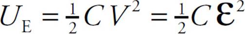
Alternatively, simply notice that all the energy stored in the capacitor will be dissipated as heat by the resistor R. But from part (d), we know that the initial energy stored in the capacitor (before discharging) was ![]() Cε2.
Cε2.
CHAPTER 14 REVIEW QUESTIONS
Section I: Multiple Choice
1. D Statement I is false: The magnetic field lines, due to a current-carrying wire, encircle the wire in closed loops. Statement II is also false: Since the magnetic force is always perpendicular to the charged particle’s velocity vector, it cannot do work on the charged particle; therefore, it cannot change the particle’s kinetic energy. Statement III, however, is true: If the charged particle’s velocity is parallel (or antiparallel) to the magnetic field lines, then the particle will feel no magnetic force.
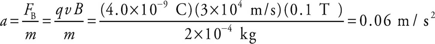
2. C The magnitude of the magnetic force is FB = qvB, so the acceleration of the particle has magnitude.
3. D By the right-hand rule, the direction of v × B is into the plane of the page. Since the particle carries a negative charge, the magnetic force it feels will be out of the page.
4. D Since FB is always perpendicular to v, v cannot be upward or downward in the plane of the page; this eliminates choices B and C. The velocity vector also cannot be to the right (choice A), since then v would be antiparallel to B, and FB would be zero. Because the charge is positive, the direction of FB will be the same as the direction of v× B. In order for v × B to be downward in the plane of the page, the right-hand rule implies that v must be out of the plane of the page.
5. A The magnetic force provides the centripetal force on the charged particle. Therefore,

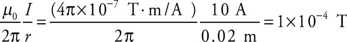
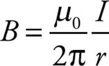
6. D The strength of the magnetic field at a distance r from a long, straight wire carrying a current I is given by the equation B = (µ0/2π)(I/r). Therefore,
7. D By Newton’s Third Law, neither choice (A) nor choice (B) can be correct. Also, as we learned in Chapter 14, Example 9, if two parallel wires carry current in the same direction, the magnetic force between them is attractive; this eliminates choices (C) and (E). Therefore, the answer must be (D). The strength of the magnetic field at a distance r from a long, straight wire carrying a current I1 is given by the equation B1 = (µ0/2π)(I1/r). The magnetic force on a wire of length ℓ carrying a current I through a magnetic field B is I(ℓ × B), so the force on Wire #2 (FB2) due to the magnetic field of Wire #1 (B1) is
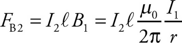
which implies

8. E The strength of the magnetic field at a distance r from a long, straight wire carrying a current I is given by the equation B = (µ0/2π)(I/r). Therefore, the strength of the magnetic field at Point P due to either wire is B = (µ0/2π)(I/![]() d). By the right-hand rule, the direction of the magnetic field at P due to the top wire is into the plane of the page and the direction of the magnetic field at P due to the bottom wire is out of the plane of the page. Since the two magnetic field vectors at P have the same magnitude and opposite directions, the net magnetic field at Point P is zero.
d). By the right-hand rule, the direction of the magnetic field at P due to the top wire is into the plane of the page and the direction of the magnetic field at P due to the bottom wire is out of the plane of the page. Since the two magnetic field vectors at P have the same magnitude and opposite directions, the net magnetic field at Point P is zero.
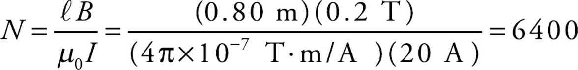
9. B The strength of the magnetic field within a hollow, ideal solenoid is given by the equation B = µ0nI, where n denotes the number of turns per unit length and I is the current in the solenoid. Therefore,
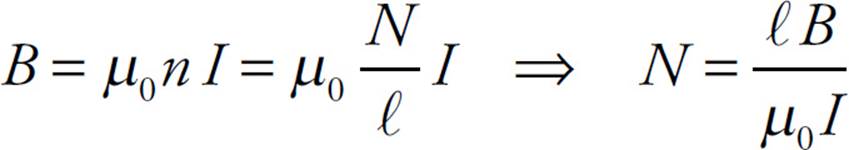
This gives
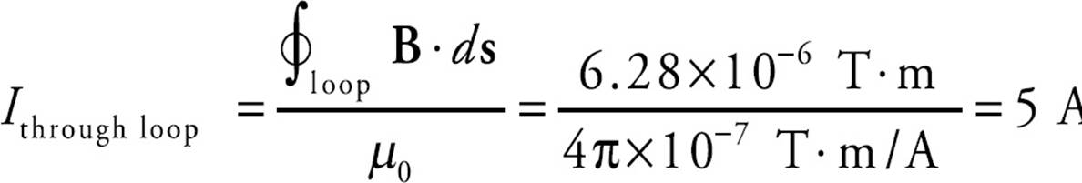
10. E By Ampere’s Law, ![]() Therefore,
Therefore,
Section II: Free Response
1. (a) The acceleration of an ion of charge q is equal to FE/m. The electric force is equal to qE, where E = V/d. Therefore, a = qV/(dm).
(b) Using a = qV/(dm) and the equation v2 = v02 = 2a d = 2a d, we get
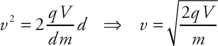
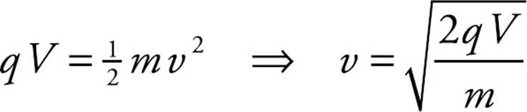
As an alternate solution, notice that the change in the electrical potential energy of the ion from the source S to the entrance to the magnetic-field region is equal to qV; this is equal to the gain in the particle’s kinetic energy.
Therefore,
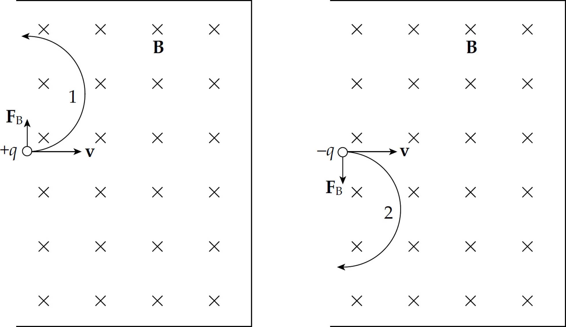
(c) (i) and (ii) Use the right-hand rule. Since v points to the right and B is into the plane of the page, the direction of v × B is upward. Therefore, the magnetic force on a positively charged particle (cation) will be upward, and the magnetic force on a negatively charged particle (anion) will be downward. The magnetic force provides the centripetal force that causes the ion to travel in a circular path. Therefore, a cation would follow Path 1 and an anion would follow Path 2.
(d) Since the magnetic force on the ion provides the centripetal force,
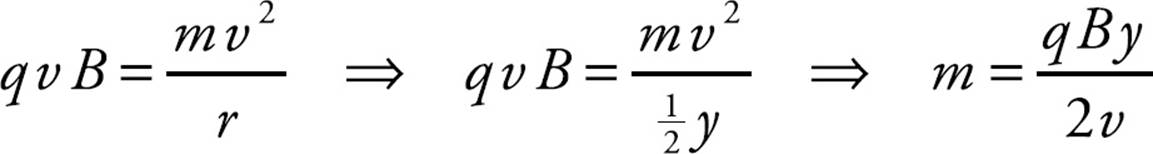
Now, by the result of part (b),
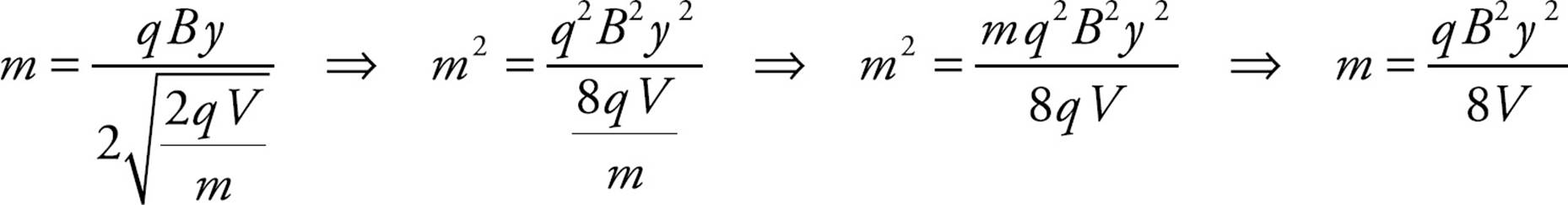
(e) Since the magnetic force cannot change the speed of a charged particle, the time required for the ion to hit the photographic plate is equal to the distance traveled (the length of the semicircle) divided by the speed computed in part (b):
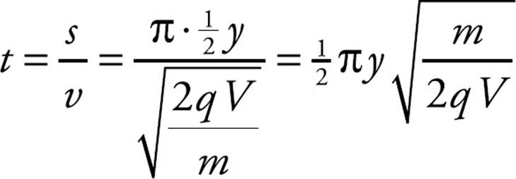
(f) Since the magnetic force FB is always perpendicular to a charged particle’s velocity vector v, it can do no work on the particle. Thus, the answer is zero.
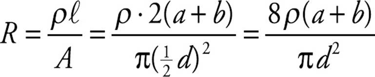
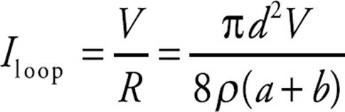
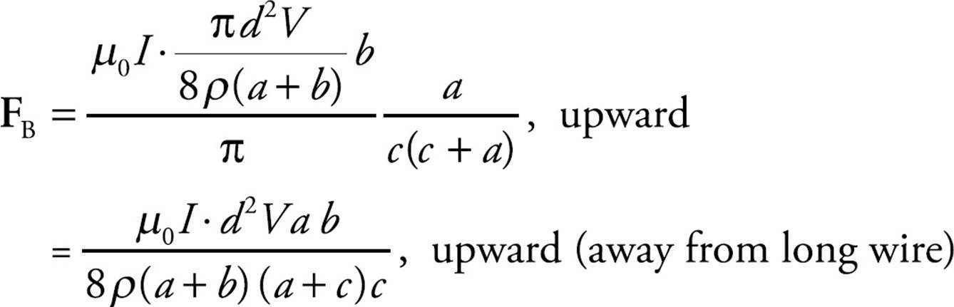
2. (a) The current in the rectangular loop is equal to V divided by the rsistance of the rectangular loop. Using the equation R = ρℓ/A, we have
Therefore, the current in the rectangular loop is
(b) We use the equation FB = I(ℓ × B) to find the magnetic force on each side of the rectangular loop. By symmetry, the magnetic forces on the sides of length a have the same magnitude but opposite direction, so they cancel. The total magnetic force on the loop is equal to the sum of the magnetic forces on the sides of length b. Current in the rectangle is directed clockwise, so the current in the bottom wire of length b (the one closer to the wire) is directed to the left and the current in the top wire of length b is directed to the right. Currents that are parallel feel an attractive force, while currents that are antiparallel feel a repulsive force. Since the strength of the magnetic field at a distance r from a long, straight wire carrying a current I is given by the equation B = (µ0/2π)(I/r), we find that the magnetic force on the bottom wire is:
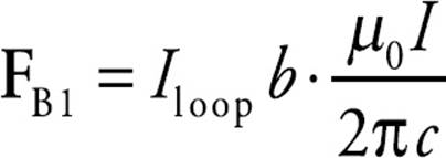 , upward (away from the long wire),
and the magnetic force on the top wire is:
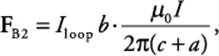 downward (toward the long wire).
Since FB1 has a greater magnitude than FB2, and the forces point in opposite directions (with the direction of the net force equaling the direction of FB1), the magnitude of the total magnetic force on the loop is equal to the difference between the magnitudes of FB1 and FB2. Therefore,
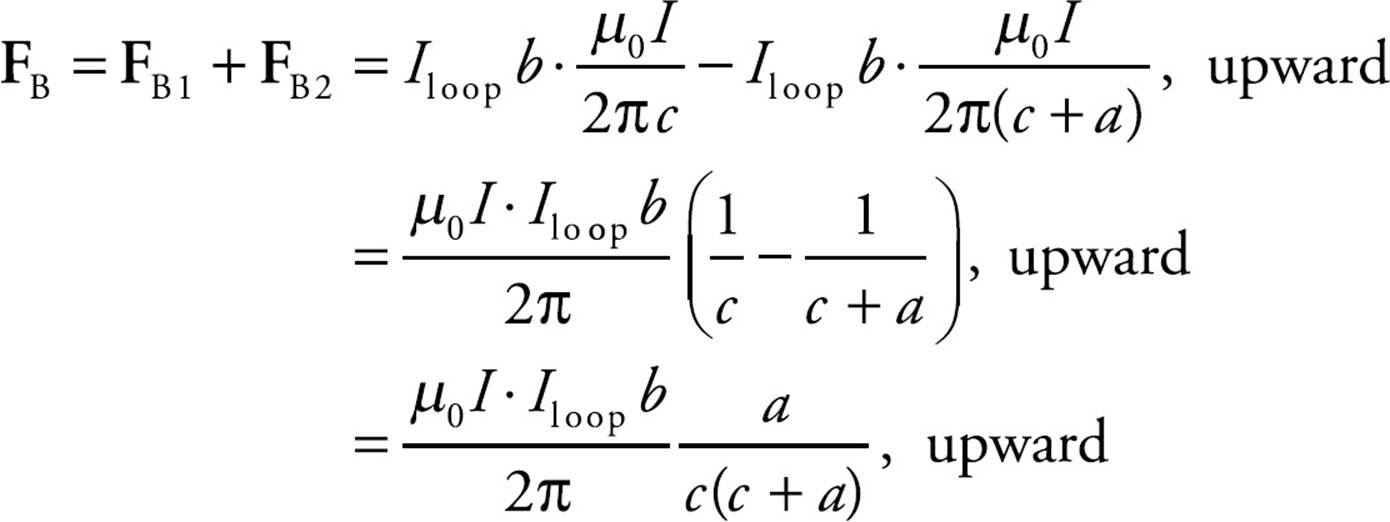
Substituting the result of part (a) for Iloop gives
(c) The circumference of the circle will be equal to the perimeter of the rectangle; thus,
(d) If the long, straight wire passes through the center of the circular loop, then the magnetic field line of the straight wire would coincide with the current in the loop. Whether the current in the loop is parallel or antiparallel to the direction of the magnetic field line makes no difference; the magnetic force on the current-carrying loop would be zero (because ℓ × B would be 0).
(e) The current in the sliding wire is directed to the right, and the magnetic field is into the plane of the page, so the right-hand rule tells us that the direction of ℓ × B [and, therefore, of FB = I(ℓ × B), the magnetic force on the sliding wire] will be upward. If this upward force is to balance the downward gravitational force, then, because ℓ = x,
3. (a) Neither of the straight portions of the wire contribute to the magnetic field at Point C; this is because ![]() is parallel (or antiparallel) to ℓ, so the cross product ℓ × r, which appears in the Biot–Savart Law, would be zero. Therefore, only the curved portion of the wire generates a magnetic field at C. Refer to the diagram below:
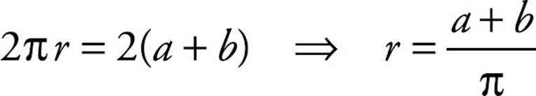
is parallel (or antiparallel) to ℓ, so the cross product ℓ × r, which appears in the Biot–Savart Law, would be zero. Therefore, only the curved portion of the wire generates a magnetic field at C. Refer to the diagram below:
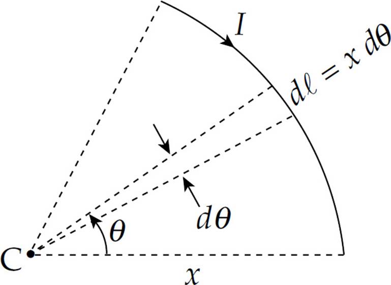
By the Biot–Savart Law, the magnetic field at C due to a length dℓ of the arc has magnitude
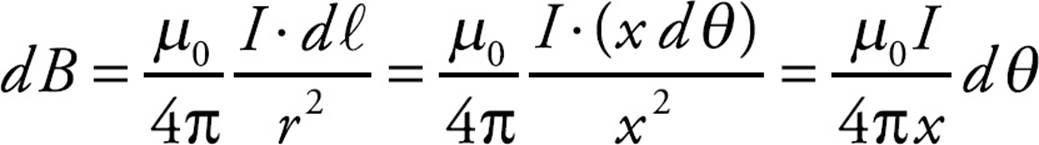
Integrating this from θ = 0 to θ = φ gives
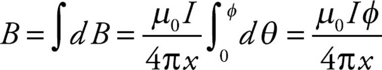
By the right-hand rule, the direction of B at C is into the plane of the page. (Either curl the fingers of your right hand in the direction of the current in the arc and notice that your thumb points into the page, or apply the right hand rule to ddℓ × ![]() .)
.)
(b) If the charged particle is placed at rest at point C, then it would feel no magnetic force. Only particles that move through magnetic fields feel a magnetic force.
(c) Since the current in the straight wire is antiparallel to the magnetic field at C, it will experience zero magnetic force (ℓ × B = 0).
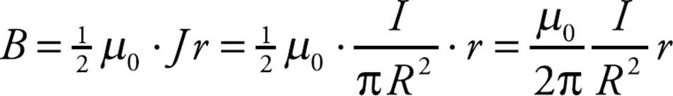
4. (a) The current in the rod is equal to the current density times the cross-sectional area of the rod: I = JA = J(πR2).
(b) (i) We apply Ampere’s Law to a circular loop of radius r < R. The magnetic field lines will be circles centered on the central axis of the rod (thus coinciding with the position of the Amperian loop drawn below):
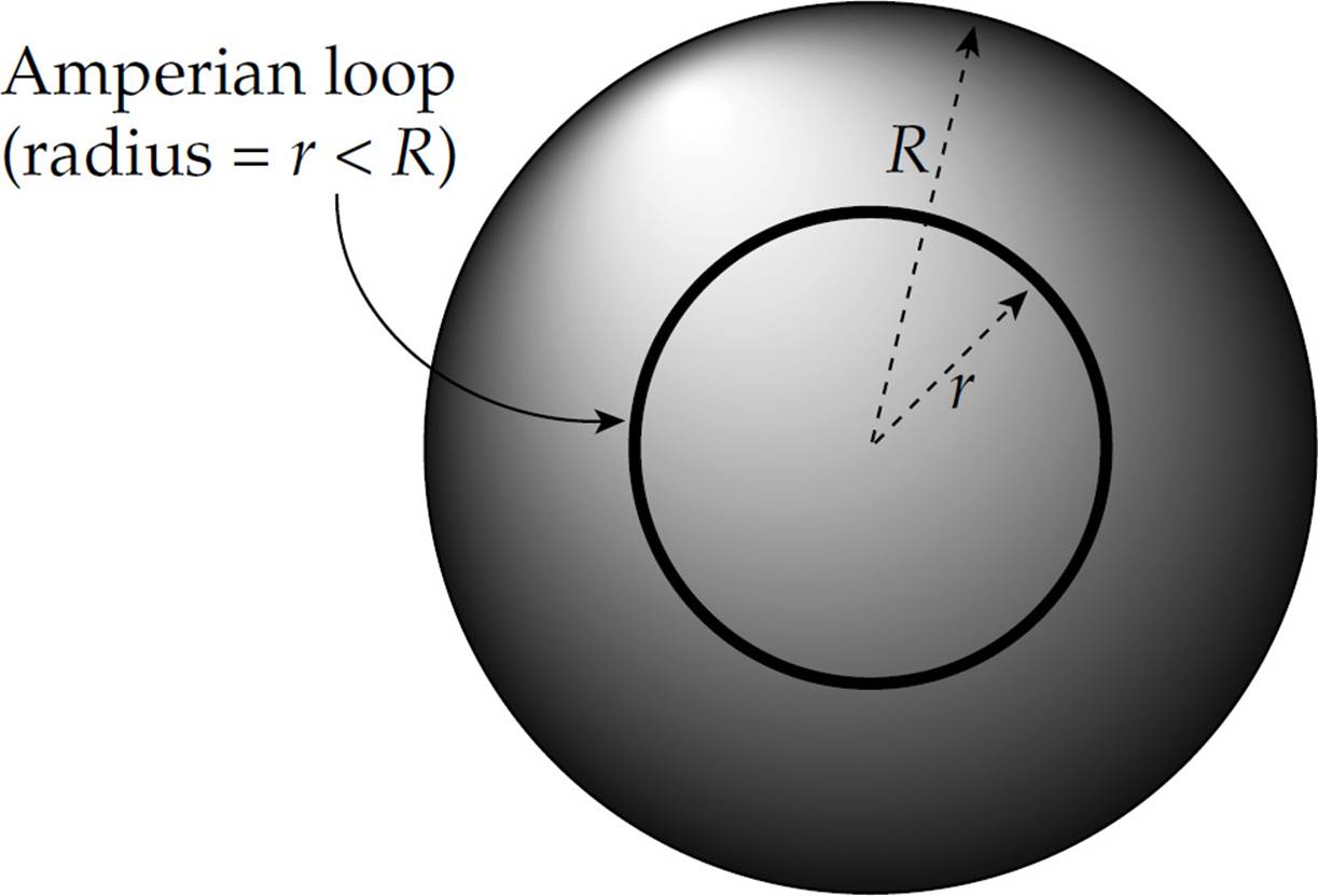
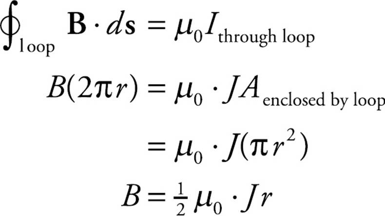
To write this result in terms of I, we simply note from part (a) that J = I/(πR2), so
(b) (ii) Applying Ampere’s Law to an Amperian loop of radius r > R,
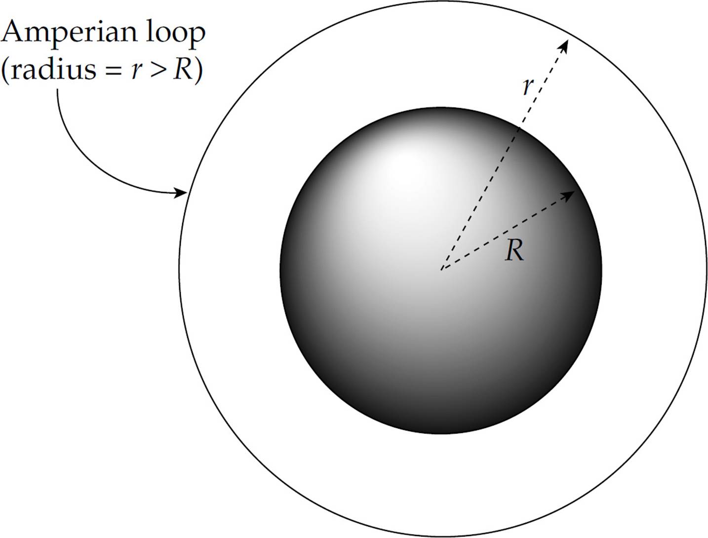
we get
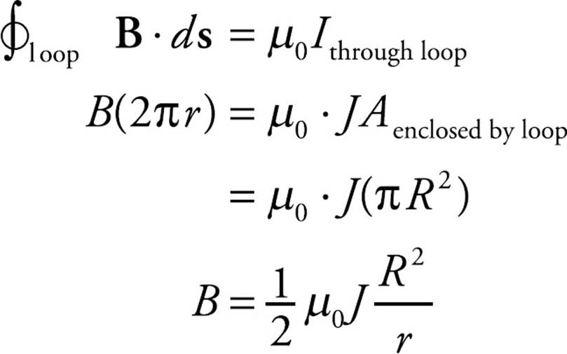
To write this result in terms of I, we once again use J = I/(π R2), giving
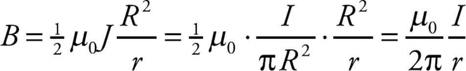
which is certainly a familiar result!
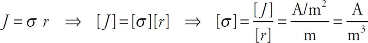
(c) Since current density is current per unit area, the units of J are A/m2. Therefore,
(d) Since the current density varies with the radial distance from the rod’s center, construct a thin ring of width dr at radius r:
The area of this ring is dA = (2πr) dr, so the current through the ring is
dI = J dA = (σr)(2πr dr) = 2πσ r2 dr
Therefore, the total current through the rod is

(e) (i) As in part (b), construct an Amperian loop of radius r < R. The current through such a loop is given by the result of Equation (1) above with r replacing R. Therefore,
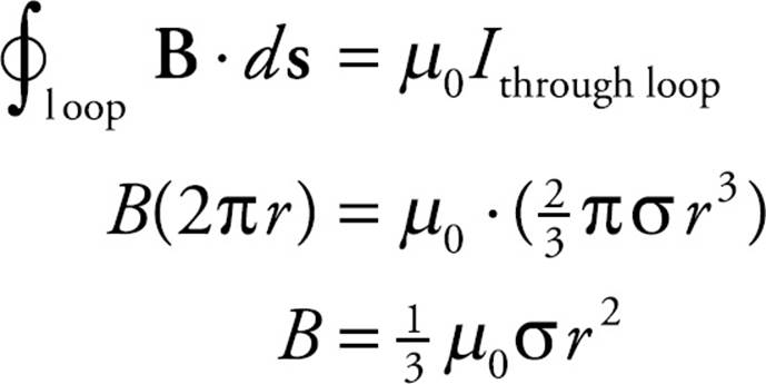
To write this result in terms of I, we simply note from part (d) that 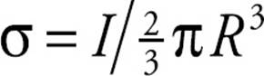 , so
, so
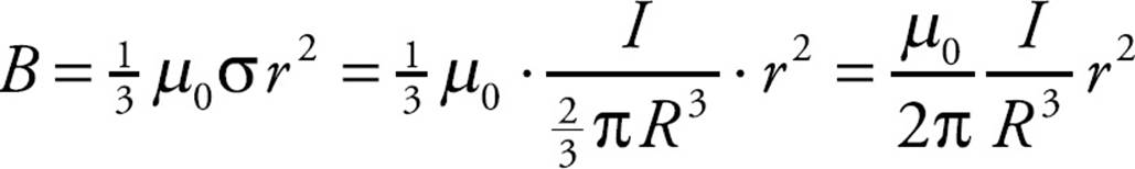
(e) (ii) We can either follow the same procedure as in (b) (ii)—and use the results of (d) and (e) (i)—or we can simply notice that outside the wire, the full current I would pass through our circular Amperian loop of radius r > R, so the magnetic field at such points must be given once again by the familiar formula
CHAPTER 15 REVIEW QUESTIONS
Section I: Multiple Choice
1. E Since v is upward and B is out of the page, the direction of v × B is to the right. Therefore, free electrons in the wire will be pushed to the left, leaving an excess of positive charge at the right. Therefore, the potential at Point b will be higher than at Point a, by ε = vBL (motional emf).
2. C Consider a small radial segment of length dr as shown:
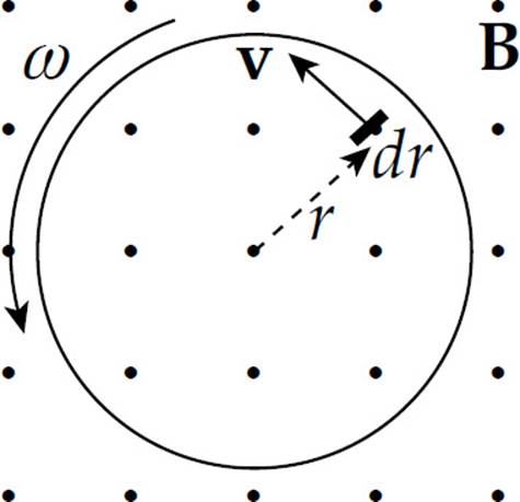
Its velocity is v =ωr, so the motional emf in this little piece is dε = (ωr)B dr. Integrating from r = 0 to r = a gives the induced emf between the center and the rim:

3. A As shown in Chapter 15, Example 3, the magnitude of the emf induced between the ends of the rod is ε = BLv = (0.5 T)(0.2 m)(3 m/s) = 0.3 V. Since the resistance is 10 Ω, the current induced will be I = V/R = (0.3 V)/(10 Ω) = 0.03 A. To determine the direction of the current, we can note that since positive charges in the rod are moving to the left and the magnetic field points into the plane of the page, the right-hand rule tells us that the magnetic force, qv × B, points downward. Since the resulting force on the positive charges in the rod is downward, so is the direction of the induced current.
4. A The magnetic field through the loop is B = µ0nI. Since its area is A = πr2, the magnetic flux through the loop is ΦB = BA = (µ0nI)(πr2). If the current changes (with  I/t = –a), then the magnetic flux through the loop changes, which, by Faraday’s Law, implies that an emf (and a current) will be induced. We get

Since the magnetic flux into the page is decreasing, the direction of the induced current will be clockwise (opposing a decreasing into-the-page flux means that the induced current will create more into-the-page flux).
5. C By definition, magnetic field lines emerge from the north pole and enter at the south pole. Therefore, as the north pole is moved upward through the loop, the upward magnetic flux increases. To oppose an increasing upward flux, the direction of the induced current will be clockwise (as seen from above) to generate some downward magnetic flux. Now, as the south pole moves away from the center of the loop, there is a decreasing upward magnetic flux, so the direction of the induced current will be counterclockwise.
6. E Since the current in the straight wire is steady, there is no change in the magnetic field, no change in magnetic flux, and, therefore, no induced emf or current.
7. A Use the equation I(t) = Imax(1 − e−t/τL). In order for I(t) to equal ![]() Imax, we must have e−t/τL =
Imax, we must have e−t/τL = ![]() Therefore,
Therefore,
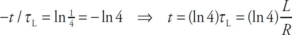
8. D The value of Imax is ε/R. Since the magnetic energy stored in an inductor is given by UB = ![]() LI2, we have
LI2, we have
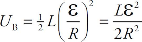
9. B By definition of self-inductance, L = N ΦB/I. The total magnetic flux through all the windings of the solenoid is NΦB, which is equal to LI. Since I = ε/R, we have
ΦB, total = L(ε/R)
10. D Faraday’s Law shows how a changing B-field generates an E-field. The Ampere-Maxwell Law shows the reverse: how a changing E-field generates a B-field.
Section II: Free Response
1. (a) Consider a small section of length dx of the rod at a distance x from the nonrotating end.
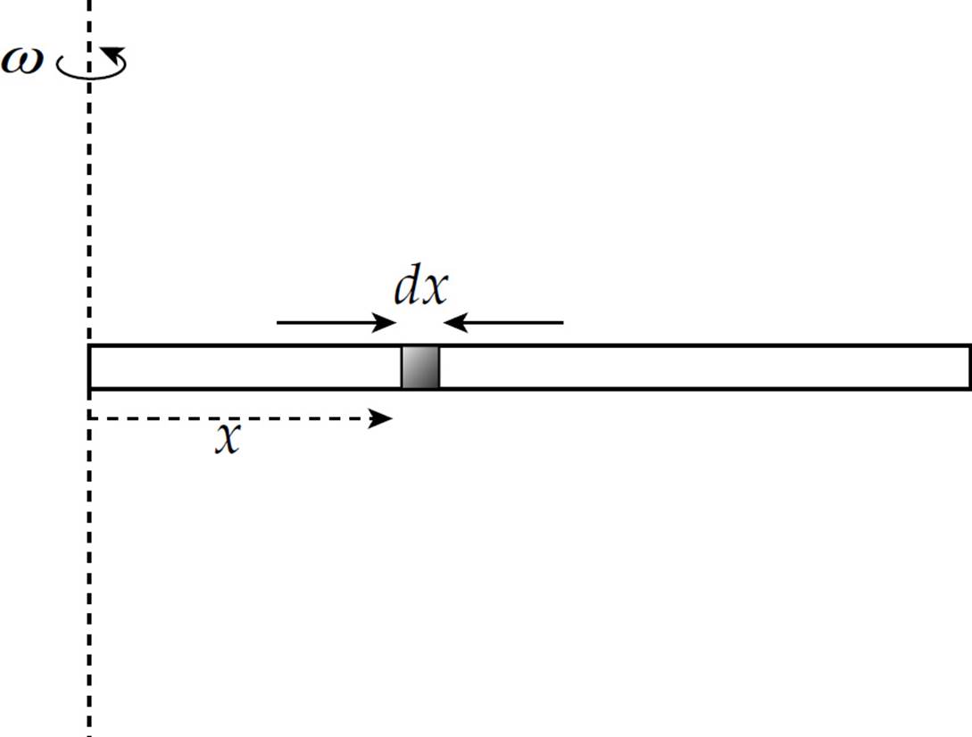
The velocity of this small piece is v = ωx, so the motional emf induced between its ends is dε = vB dx = ωxB dx. Integrating this from x = 0 to x = ℓ gives
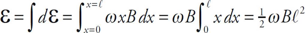
(b) Refer to the view from above of the rod:
By the right-hand rule, the direction of v × B is to the right, so the magnetic force on free electrons will be to the left, leaving excess positive charge at the right (rotating) end.
(c) Consider a small section of length dy at a distance y from the straight wire.
Since the magnetic field at the position of this section is (µ0/2π)(I/y), the motional emf induced between its ends is dε = vB dy = v(µ0/2π)(I/y) dy. Integrating this from y = a to y = a + ℓ gives
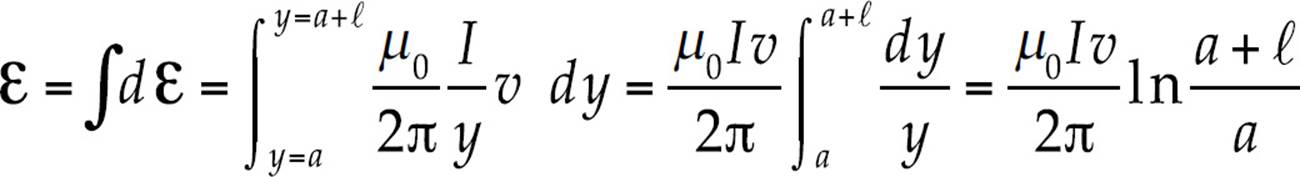
(d) The magnetic field above the wire (where the rod is sliding) is out of the plane of the page, so the direction of v × B is downward.
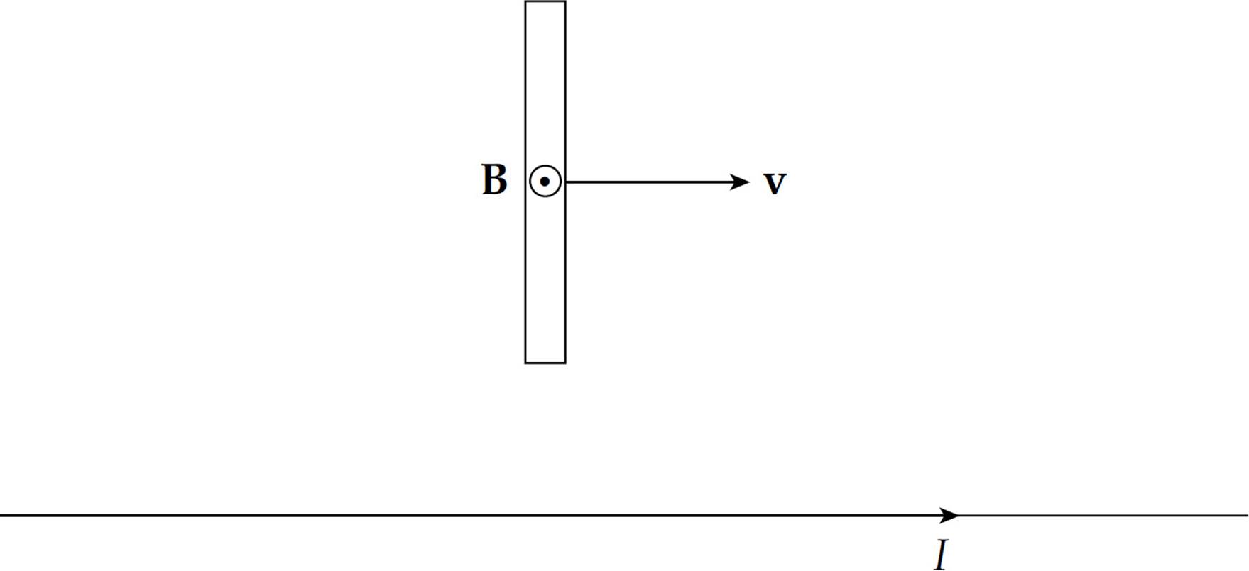
Therefore, free electrons in the rod will be pushed upward to the far end of the rod, causing it to become negatively charged.
2. (a) As the loop rotates, the angle between the normal to the loop’s enclosed area and B changes according to the equation θ = ωt. Therefore, the magnetic flux through the loop is
ΦB(t) = BA cosθ = BA cos ωt = abB cos ωt
(b) According to Faraday’s Law, the induced emf is equal to the rate of change of magnetic flux through the loop (with a minus sign included to conform to Lenz’s Law). Therefore,

(c) Using the result of part (b) with the equation I = ε/R, we find that the induced current is a function of time given by
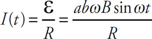
(d) As the loop rotates from θ = 0 to θ = π/2, the magnetic flux (to the right, the +x direction) through the loop decreases from BA = abB to zero. To oppose this decreasing flux to the right, the current will be induced in a direction to generate a magnetic field with a component in the +x direction. The current will be flowing from point 3 to 4 to 1 to 2 to 3.
(e) The rate at which energy is dissipated as heat in the loop is given by the equation P = I2R = (ε/R)2R = ε2/R, so
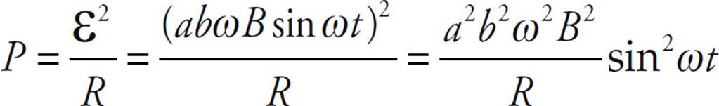
In one revolution, ω t increases from 0 to 2π, so the energy dissipated is
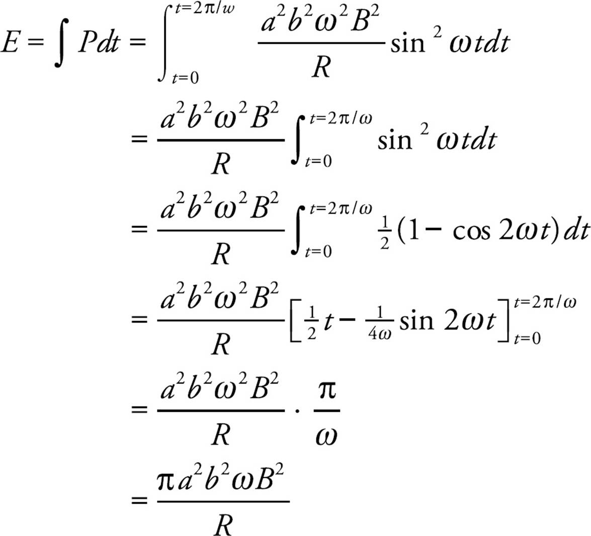
(f) The work done by the externally provided torque is transformed into the heat lost in the loop. Equivalently, the rate at which the torque does work is equal to the rate at which heat energy is dissipated in the wires of the loop. Since the power associated with the external torque is P = ωτ, the result of part (e) gives
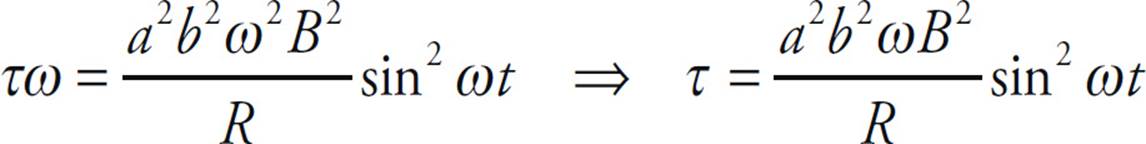
3. (a) Construct an Amperian loop of radius R whose center coincides with the center of the toroid. Then only the current in the inner set of N windings pierces through the area bounded by the loop, so Ampere’s Law becomes
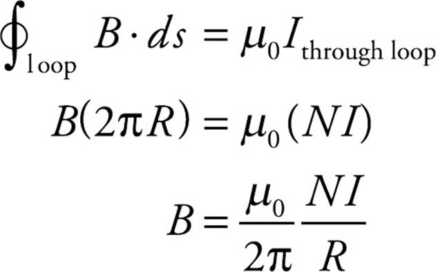
(b) Because there is no magnetic field outside the toroid, the magnetic flux through the loop is equal to B times the cross-sectional area of the toroid (which is πa2). Therefore, by Faraday’s Law,
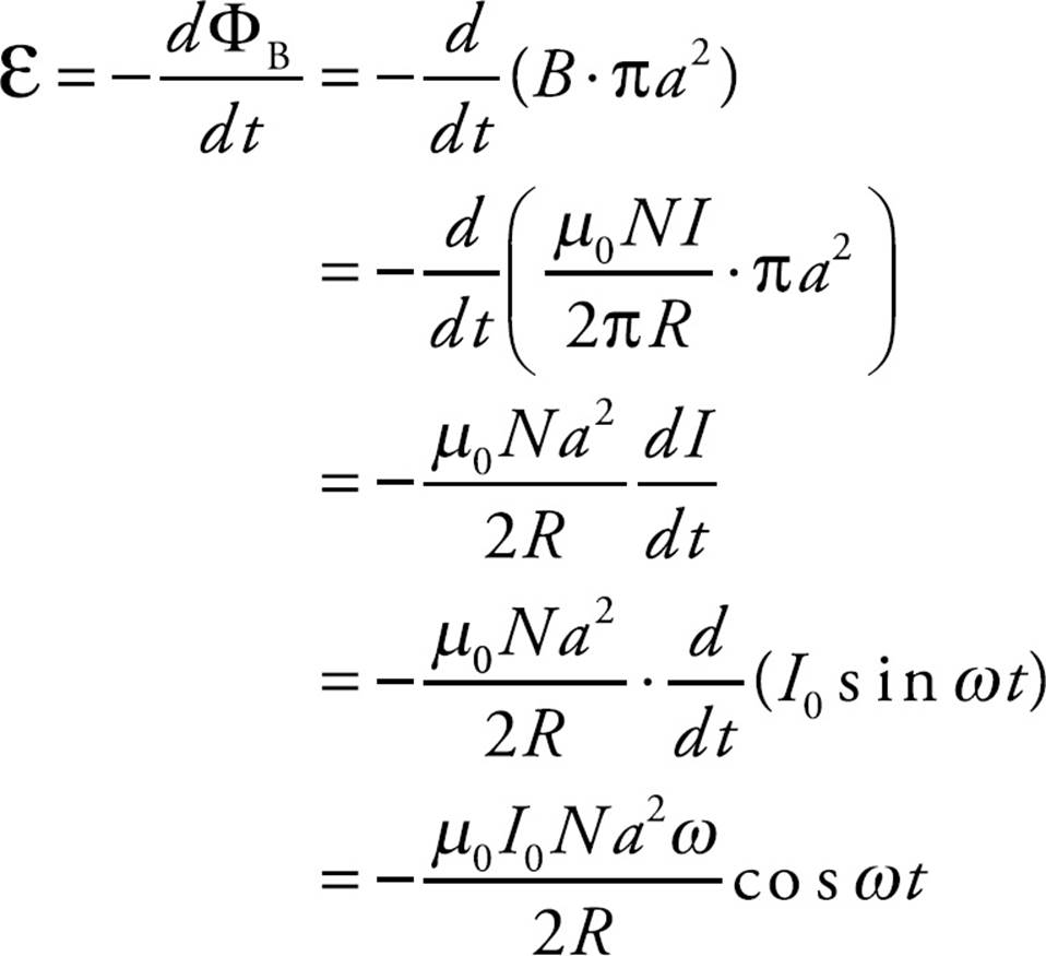
(c) Writing Faraday’s Law in the form
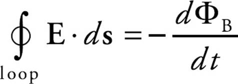
and applying it to the circular loop of radius 2a, we find that
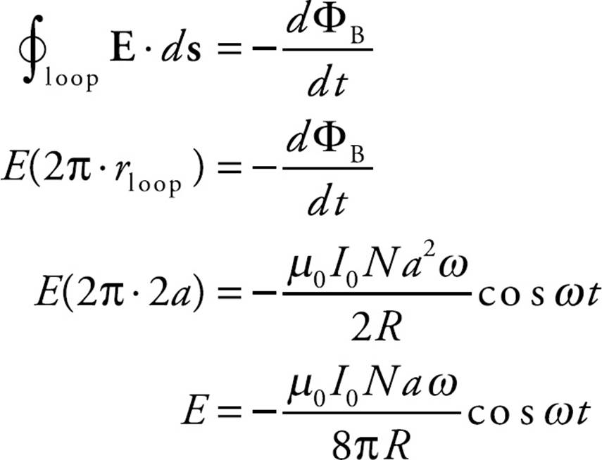
(d) By definition, the self-inductance, L, is equal to NΦB/I. Since
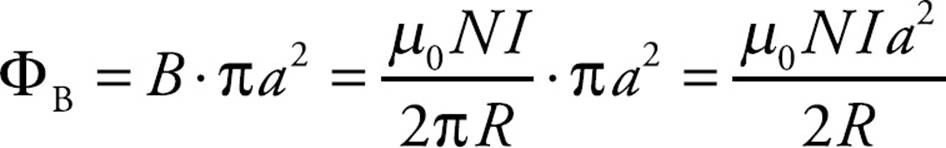
as we calculated in the solution to part (b), we find that
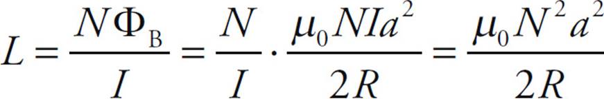
4. (a) When the switch is initially moved, the inductor prevents an instantaneous change in current. So the current in the inductor, and the rest of the circuit, is zero.
(b) After the steady state condition is reached, the inductor has no emf (since di/dt = 0) so the current in the circuit can be found using Ohm’s Law.
V = IR
10 V = I • 10W
I = 1 A
(c) The current in the inductor does not change immediately, so the current in the inductor is 1 A.
(d) The current through the resistor is also 1 A since it is in series with the inductor now. So the voltage drop across the resistor, VR, can be found using Ohm’s Law, VR =(1A)(5Ω) = 5V. The voltage across the inductor is the same (since the voltage drops around the loop must add up to zero). Thus,
εL = 5 V