Process Technology: An Introduction - Haan A.B. 2015
8 Absorption and stripping
8.5 Industrial contactors
The industrially most frequently used absorbers are packed columns, tray towers, spray columns, and bubble columns.
8.5.1 Packed columns
Packed columns are the units most often used in absorption operations (Fig. 8.4). Usually they are cylindrical columns up to several meters in diameter and over 10 meters high. A large gas-liquid interface is achieved by introducing various packings into the column. The packing is placed on a support whose free cross section should be at least equal to the packing porosity. Liquid is fed in at the top of the column and distributed over the packing, through which it flows downwards. To guarantee a uniform liquid distribution over the cross section of the column, a liquid distributor is employed. The gas flows upward countercurrent to the falling liquid, which absorbs the soluble species from the gas. The gas, which is not absorbed, exits from the top of the column, usually through a mist eliminator. The mist eliminator separates liquid drops entrained by the gas from the packing. The separator may be a layer of the packing or mesh, or it may be specially designed.
Packed columns are preferable to tray columns for small installations, corrosive service, liquids with a tendency to foam, very high liquid-to-gas ratios, and low pressure drop applications. In the handling of corrosive gases, packing, but not trays, can be made from ceramic or plastic materials. Packed columns are also advantageous in vacuum applications, because the pressure drop, especially for regularly structured packings, is usually less than in tray columns. In addition packed columns offer greater flexibility, because the packing can be changed with relative ease to modify column-operating characteristics.
The main virtues of a good packing are a large specific surface area, high void fraction (porosity), chemical resistance to liquid and gas, high mass transfer rates in both phases, a small pressure drop, and low cost. Two of the features mentioned above characterize the packing particularly well. These are the specific surface of the packing and the void fraction. The specific surface of the packing is the total surface area of all packing elements contained in a unit volume. Usually the specific surface area of industrial packings ranges from 100 to 1000 m2/m3. The void fraction is the ratio of the free volume to the bed volume. For ceramic packings the void fraction is usually about 0.7, while for metal packing it is about 0.95 and more.
Packings may be divided into two main groups: random and structured. Structured packings are manufactured for a given column diameter and column height. Usually the same packing cannot be used in columns with different diameters. Random packings may be relocated to various columns.
The most popular random packings are rings. Raschig rings have a large specific packing surface and high porosity. They are hollow cylinders with an external diameter equal to the ring height. They can be made of ceramic, metal, graphite, or plastic. Since the time when Raschig introduced his rings in industry, they have been continuously modified. Fig. 8.5 shows a Raschig ring and its main modified forms. The objective in modifying the rings is to increase the mass transfer area and the porosity of the packing, and to guarantee a low-pressure drop and good conditions for mixing the gas and liquid phases. From experimental investigations it follows that the most efficient of all the types of ring are Pall rings.
Recently, the application of structured packing in absorption has increased rapidly owing to the fact that it has a larger mass transfer area than random packing does. Another advantage is that by using this packing it is possible, in contrast to random packing, to obtain the same values for the mass transfer coefficient in the entire column. Furthermore it is also easier and cheaper to install columns which already have the structured packing inside rather than to assemble a column and then fill it with random packing on site. One of the first structured packings is the Sulzer BX packing. A classical form of the Sulzer BX packing is a grid strip bent alternately at an angle of about 300 to the column axis. Bent strips form bunches located in the column one on top of the other. The liquid and the gas flow in channels which change their flow direction while passing through the bunches. Fig. 8.6 presents schematically the Sulzer BX packing. Several modifications have been recently introduced to this packing.
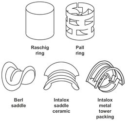
Fig. 8.5: Schematic drawing of various random packings.
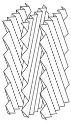
Fig. 8.6: Schematic of structured Sulzer BX packing.
8.5.2 Tray columns
Another basic type of equipment widely applied in absorption processes is a tray column (Fig. 8.4). The diameter and height of the column can reach 10 and 50 m, respectively, but usually they are much smaller. In tray columns, various tray constructions guarantee good contact of the gas with the liquid. Taking into account the whole column, the flow of the gas with the liquid has a countercurrent character. Liquid is supplied to the highest tray, flows along it horizontally and, after reaching a weir, flows through a downcomer to a tray below. Gas is supplied below the lowest tray, and then it flows through perforations in the tray and bubbles through a liquid layer. The application of such a flow pattern is aimed at ensuring the maximum mass transfer area and high turbulence of the gas and liquid phases, which results in high mass transfer coefficients in both phases. The distances between trays should be such that liquid droplets entrained by the gas are separated from the liquid and the gas is separated from the liquid in the downcomer. Usually, the tray-to-tray distance ranges from 0.2 to 0.6 m and depends mainly on the column diameter and the liquid load of the tray.
Tray columns are particularly well suited for large installations and low-tomedium liquid flow rate applications. In general they offer a wider operating window for gas and liquid flow than a countercurrent packed column. That is, they can handle high gas flow rates and low liquid flow rates that would cause flooding in a packed column. Tray columns are also preferred in applications which have large heat effects, since cooling coils are more easily installed in tray towers and liquid can be withdrawn more easily from trays than from packings for external cooling. Furthermore they are advantageous for separations which require tall columns with a large number of transfer units, because they are not subject to any channeling of vapor and liquid streams, which can cause problems in tall packed columns. The main disadvantages of tray columns are their high capital cost, especially when bubble-cap trays or special proprietary design are used, and their sensitivity to foaming.
As mentioned above, the trays most widely applied in apparatus mass transfer processes are ones with a cross flow of phases. There is a variety of tray designs for this flow. On an industrial scale three tray types are most important (Fig. 8.7):
· — bubble cap tray;
· — sieve tray;
· — valve tray.
The bubble cap tray was used in absorption and distillation for many years until the early 1950s. Due to high production costs the classical form of the bubble cup trays is not recommended. Only under conditions where the column load of gas and liquid is changing over a wide range is the use of these trays justified. On classical bubble cap trays, gas flows through risers under the caps and then in the form of bubbles passes through a liquid layer. In the most recent design solutions flat caps or caps without risers are applied. Because of an appreciable decrease in risers a decrease in the cost of tray production and gas pressure drop on the tray are achieved while maintaining high efficiency of the tray.
A characteristic feature of valve trays is that they can operate efficiently over a very wide range of column loading with gas and liquid. Perforations of 35 to 50 mm diameter made in the trays are equipped with valves which, depending on the gas and liquid flow rates, open to a greater or lesser extent. There is always, irrespective of the gas flow velocity, some minimum opening of the valve. With an increase in the gas velocity the valve floats up, opening to the maximum position.
Taking into account low costs, the most important and most frequently used trays now are sieve trays. The steel sheets are perforated in such a way that the perforation forms equilateral triangles. Initially, the diameter of the holes in the sieve trays was 3-6 mm. Now, trays with holes reaching 25 mm are used. However, the most frequently applied trays have holes of about 5 mm in diameter.
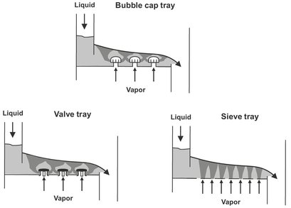
Fig. 8.7: Drawing of the most important industrial tray types.
8.5.3 Spray towers
In spray towers liquid is sprayed as fine droplets which make contact with a cocurrently or counter currently flowing gas (Fig. 8.4). The gas and liquid flows are similar to plug flow. Spray contactors are used almost entirely for applications where pressure drop is critical, such as flue gas scrubbing. They are also useful for slurries that might plug packings or trays. Other important applications include particles removal and hot gas quenching. When used for absorption, spray devices are not applicable to difficult separations because they are limited to only a few equilibrium stages even with countercurrent spray column designs. The low efficiency of spray columns originates from the entrainment of droplets in the gas and back mixing of the gas induced by the sprays. The high energy consumed for atomizing liquid and liquid entrainment in the gas outlet stream are two additional important disadvantages.
8.5.4 Bubble columns
Bubble columns (Fig. 8.8) are finding increasing application in processes where absorption is accompanied by a chemical reaction. They are also widely used as chemical reactors in processes where gas, liquid, and solid phases are involved. In bubble columns the liquid is a continuous phase, while the gas flows through it in the form of bubbles, The character of the gas flow is well represented by plug flow, while that of the liquid is between plug and ideally mixed flow. These absorbers can operate in cocurrent and countercurrent phase flow.
Bubble columns are particularly well suited for applications where significant liquid hold-up and long liquid residence time are required. An advantage of these columns is their relatively low investment cost, a large mass transfer area, and high mass transfer coefficients in both phases. Disadvantages of bubble columns include a high-pressure drop of the gas and a significant back mixing of the liquid phase. The latter disadvantage can be reduced by introducing an inert packing of high porosity to the bubble column. Such a packing eliminates to a large extent the effects of liquid phase mixing along the column height. In addition the packing may also cause an increase in the mass transfer surface area with relation to the bubble column at the same flows of both phases. The advantages of bubble columns appreciably exceed their disadvantages, and therefore an increasing number of these columns are applied in industry. The column diameter sometimes exceeds 5 m, and its height reaches over 10 m. Beside the modified columns mentioned above there are many design solutions which are particularly useful in cases where in addition to the gas and liquid phase there is also a solid phase present.
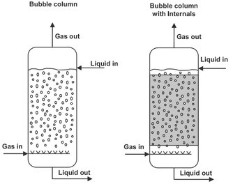
Fig. 8.8: Schematic of a bubble column absorber, without and with internal packing.
Nomenclature
A |
L/K G, absorption factor |
[-] |
f |
fraction absorbed or stripped |
[-] |
G |
gas flow |
[mol s-1] |
H |
Henry coefficient |
[-] |
K |
equilibrium constant |
[-] |
Kq |
distribution coefficient |
[—] |
L |
liquid flow |
[mol s-1] |
N |
number of (theoretical) stages |
[-] |
p |
partial pressure |
[N m-2] |
P° |
saturation pressure |
[N m-2] |
Ptot |
total pressure |
[N m-2] |
S |
K — G/L, stripping factor |
[-] |
x, y |
mole fraction |
[-] |
y |
activity coefficient |
[-] |
Indices
A |
components |