AP Physics C Exam
Part IV
Content Review for the AP Physics C Exam
Chapter 14
Magnetic Forces and Fields
INTRODUCTION
In Chapter 11, we learned that electric charges are the sources of electric fields and that other charges experience an electric force in those fields. The charges generating the field were assumed to be at rest, because if they weren’t, then another force field would have been generated in addition to the electric field. Electric charges that move are the sources of magnetic fields, and other charges that move can experience a magnetic force in these fields. Not only do moving charges create magnetic fields, but certain materials that are called ferromagnetic can produce permanent magnets. Iron, nickel, and cobalt are three examples of ferromagnetic materials. When a bar magnet is suspended from a pivot, one end of the magnet will point north, and one end will point south. The region where the field is strongest in the magnet is called the pole, and thus a permanent magnet will have a north pole and a south pole. Opposite poles attract and like poles repel. When a compass (a small suspended magnet) is placed in a magnetic field, the north pole of the compass will thus point to the south pole of the magnet. We define the direction of the magnetic field to be parallel to the direction that the north pole of a compass needle is pointing.
One common misconception is to confuse magnetic effects and electrostatic effects. Since north poles repel each other, and positive charges repel each other, some students assume north poles repel stationary positive charges. This is incorrect because magnetic fields (and thus north and south poles) only exert forces on moving charges. And the force is perpendicular to both the velocity of the charged particle and the magnetic field.
THE MAGNETIC FORCE ON A MOVING CHARGE
If a particle with charge q moves with velocity v through a magnetic field B, it will experience a magnetic force, FB, with magnitude:

where θ is the angle between v and B. From this equation, we can see that if the charge is at rest, then v = 0 immediately gives us FB = 0. This tells us that magnetic forces only act on moving charges. Also, if v is parallel (or antiparallel) to B, then FB = 0 since, in either of these cases, sin θ= 0. So, only charges that cut across the magnetic field lines will experience a magnetic force. Furthermore, the magnetic force is maximized when v is perpendicular to B, since if θ = 90°, then sin θ is equal to 1, its maximum value.
The direction of FB is always perpendicular to both v and B and depends on the sign of the charge q and the direction of v × B (which is given by the right-hand rule).

Equations (1) and (2) can be summarized by a single equation:

Note that there are fundamental differences between the electric force and magnetic force on a charge. First, a magnetic force acts on a charge only if the charge is moving; the electric force acts on a charge whether it moves or not. Second, the direction of the magnetic force is always perpendicular to the magnetic field, while the electric force is always parallel (or antiparallel) to the electric field.
The SI unit for the magnetic field is the tesla (abbreviated as T) which is one newton per ampere-meter. Another common unit for magnetic field strength is the gauss (abbreviated as G): 1 G = 10–4 T.
Example 1 A charge +q = +6 × 10⁻⁶ C moves with speed v = 4 × 10⁵ m/s through a magnetic field of strength B = 0.4 T, as shown in the figure below. What is the magnetic force experienced by q?
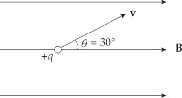
Solution. The magnitude of FB is
FB = qvB sin θ = (6 × 10⁻⁶ C)(4 × 10⁵ m/s)(0.4 T) sin 30° = 0.48 N
By the right-hand rule, the direction of v × B is into the plane of the page, which is symbolized by ⊗. Because q is a positive charge, the direction of FB on q is also into the plane of the page.
Example 2 A particle of mass m and charge +q is projected with velocity v (in the plane of the page) into a uniform magnetic field B that points into the page. How will the particle move?
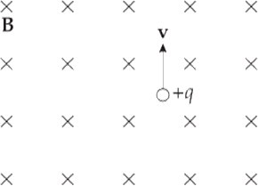
Solution. Since v is perpendicular to B, the particle will feel a magnetic force of strength qvB, which will be directed perpendicular to v (and to B) as shown
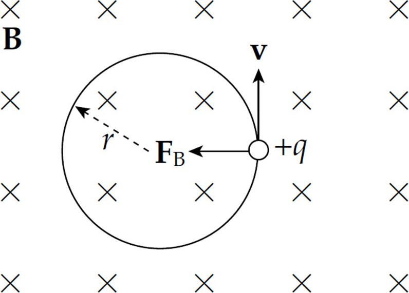
Since FB is always perpendicular to v, the particle will undergo uniform circular motion; FB will provide the centripetal force. Notice that, because FB is always perpendicular to v, the magnitude of v will not change, just its direction. Magnetic forces cannot change the speed of a charged particle, they can only change its direction of motion. The radius of the particle’s circular path is found from the equation FB = FC:

Example 3 A particle of charge –q is shot into a region that contains an electric field, E, crossed with a perpendicular magnetic field, B. If E = 2 × 10⁴ N/C and B = 0.5 T, what must be the speed of the particle if it is to cross this region without being deflected

Solution. If the particle is to pass through undeflected, the electric force it feels has to be canceled by the magnetic force. In the diagram, the electric force on the particle is directed upward (since the charge is negative and E is downward), and the magnetic force is directed downward (since the charge is negative and v × B is upward). So FE and FB point in opposite directions, and in order for their magnitudes to balance, qE must equal qvB, so v must equal E/B, which in this case gives

Example 4 A particle with charge +q, traveling with velocity v, enters a uniform magnetic field B, as shown below. Describe the particle’s subsequent motion.
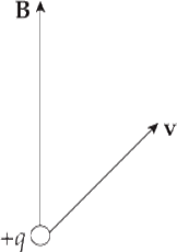
Solution. If the particle’s velocity were parallel to B, then it would be unaffected by B. If v were perpendicular to B, then it would undergo uniform circular motion (as we saw in Example 2). In this case, v is neither purely parallel nor perpendicular to B. It has a component (v1) that’s parallel to B and a component (v2) that’s perpendicular to B.
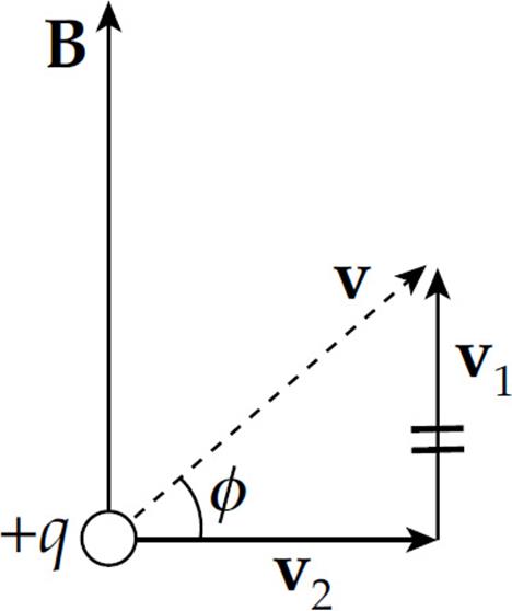
Component v1 will not be changed by B, so the particle will continue upward in the direction of B. However, the presence of v2 will create circular motion. The superposition of these two types of motion will cause the particle’s trajectory to be a helix; it will spin in circular motion while traveling upward with the speed v1 = v sin φ:

THE MAGNETIC FORCE ON A CURRENT-CARRYING WIRE
Since magnetic fields affect moving charges, they should also affect current-carrying wires. After all, a wire that contains a current contains charges that move.
Let a wire of length ℓ be immersed in magnetic field B. If the wire carries a current I, then the magnitude of the magnetic force it feels is
FB = IℓB sin θ
where θ is the angle between ℓ and B. Here, the direction of ℓ is the direction of the current, I. The direction of FB is the same as the direction of ℓ × B, and these properties can be summarized in a single equation:
Example 5 A U-shaped wire of mass m is lowered into a magnetic field B that points out of the plane of the page. How much current I must pass through the wire in order to cause the net force on the wire to be zero?
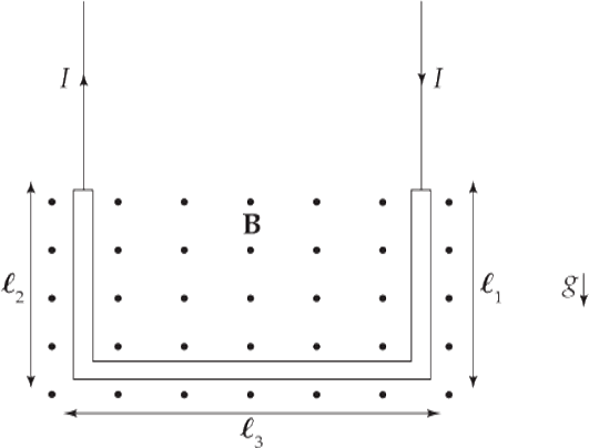
Solution. The total magnetic force on the wire is equal to the sum of the magnetic forces on each of the three sections of wire. The force on the first section (the right, vertical one), FB1, is directed to the left (applying the right-hand rule to ℓ1 × B; ℓ1 points downward), and the force on the third piece (the left, vertical one), FB3, is directed to the right. Since these pieces are the same length, these two oppositely directed forces have the same magnitude, Iℓ1B = Iℓ2B, and they cancel. So the net magnetic force on the wire is the magnetic force on the middle piece. Since ℓ2points to the left and B is out of the page, ℓ2 × B [and, therefore, FB2 = I(ℓ2 × B)] is directed upward.
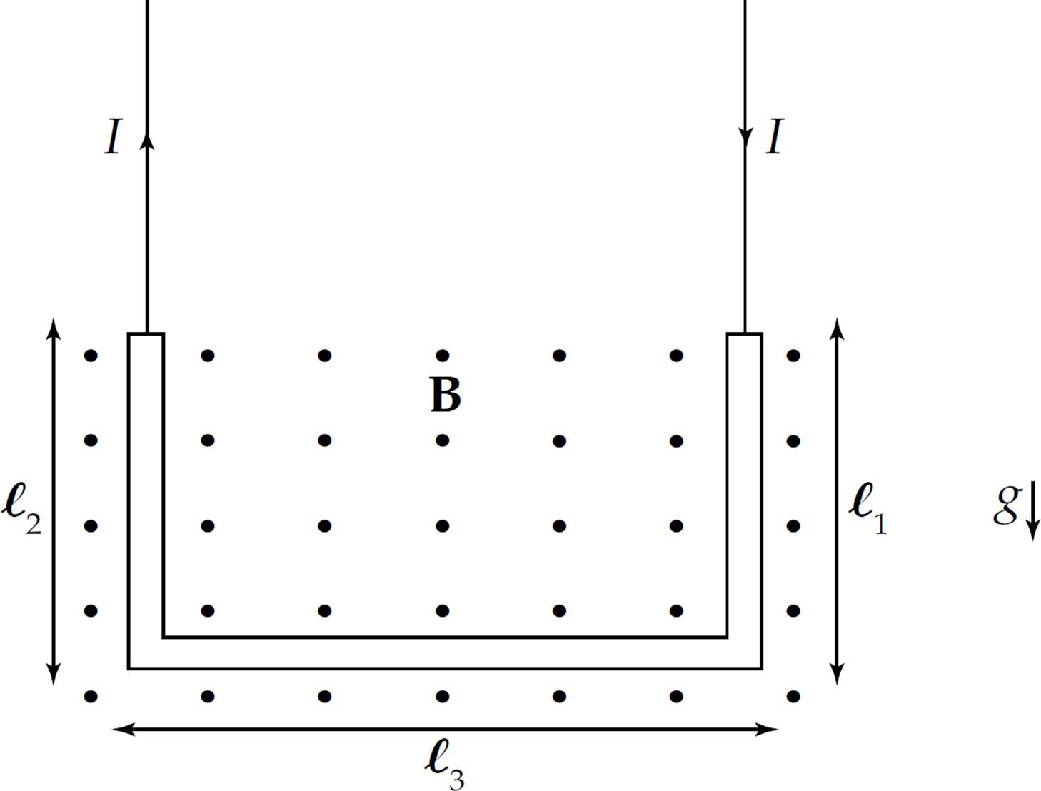
Since the magnetic force on the wire is Iℓ2B, directed upward, the amount of current must create an upward magnetic force that exactly balances the downward gravitational force on the wire. Because the total mass of the wire is m, the resultant force (magnetic + gravitational) will be zero if

Example 6 A rectangular loop of wire that carries a current I is placed in a uniform magnetic field, B, and is free to rotate as shown in the diagram below. What torque does it experience?
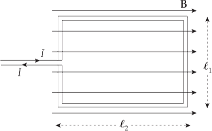
Solution. Ignoring the tiny gap in the vertical left-hand wire, we have two wires of length ℓ1 and two of length ℓ2. There is no magnetic force on either of the sides of the loop of length ℓ2, because the current in the top side is parallel to B and the current in the bottom side is antiparallel toB. The magnetic force on the right-hand side points out of the plane of the page, while the magnetic force on the left-hand side points into the plane of the page.
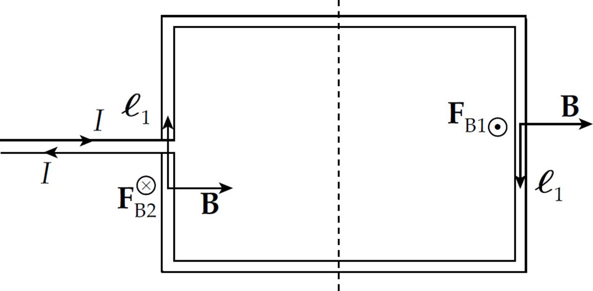
If the loop is free to rotate, then each of these two forces exerts a torque that tends to turn the loop in such a way that the right-hand side rises out of the plane of the page and the left-hand side rotates into the page. Relative to the axis shown above (which cuts the loop in half), the torque of FB1 is

and the torque of FB2 is

Since both these torques rotate the loop in the same direction, the net torque on the loop is
τ1 + τ2 = Iℓ1ℓ2B
Example 7 The middle portion of the wire shown below is bent into the shape of a semicircle of radius r. The wire carries a current I. What’s the total magnetic force that acts on the wire in the field, B?
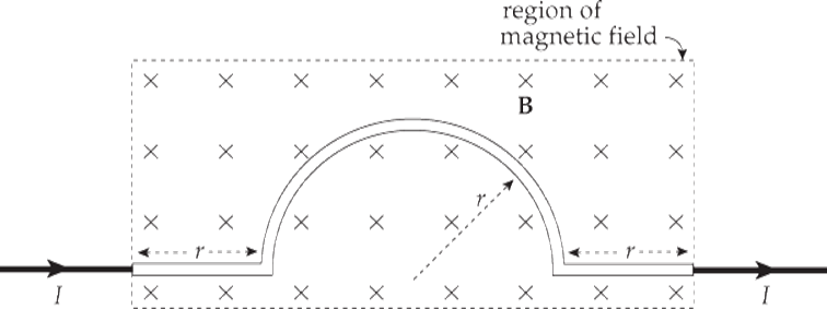
Solution. Let’s first find the magnetic force that acts on the two straight sections. The magnitude of the magnetic force on each section is IℓB = IrB, and since ℓ points to the right in both sections, the magnetic force on each of them points upward.
On the semicircle, the direction of ℓ is not constant, so we have to split this section into small pieces with lengths dℓ = rdθ and then use the equation dF = I(dℓ × B). In the diagram below, the direction of dF is radially away from the center of the semicircle.

The total horizontal force on the semicircle, FBx, can be found by integrating dFBx = dF cos θ from θ = 0 to θ = π:
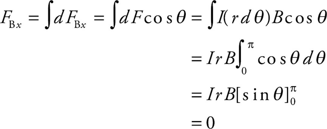
The total vertical force on the semicircle, FBy, can be found by integrating dFBy = dF sin θ from θ = 0 to θ = π:
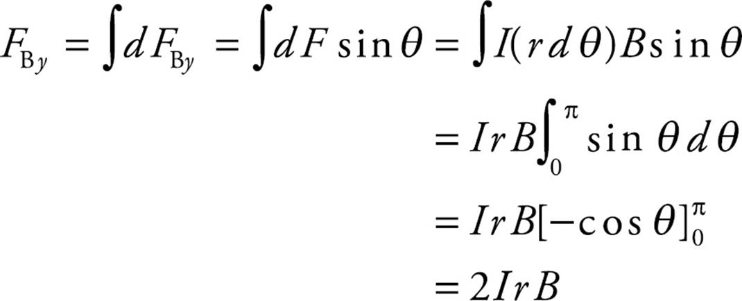
So, the total magnetic force on the wire is (IrB, upward) + (2IrB, upward) + (IrB, upward) = 4IrB, upward.
MAGNETIC FIELDS CREATED BY CURRENT-CARRYING WIRES
As we said at the beginning of this chapter, the sources of magnetic fields are electric charges that move; they may spin, circulate, move through space, or flow down a wire. For example, consider a long, straight wire that carries a current I. The current generates a magnetic field in the surrounding space, of magnitude:
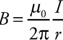
where r is the distance from the wire. The symbol µ0 denotes a fundamental constant called the permeability of free space. Its value is:

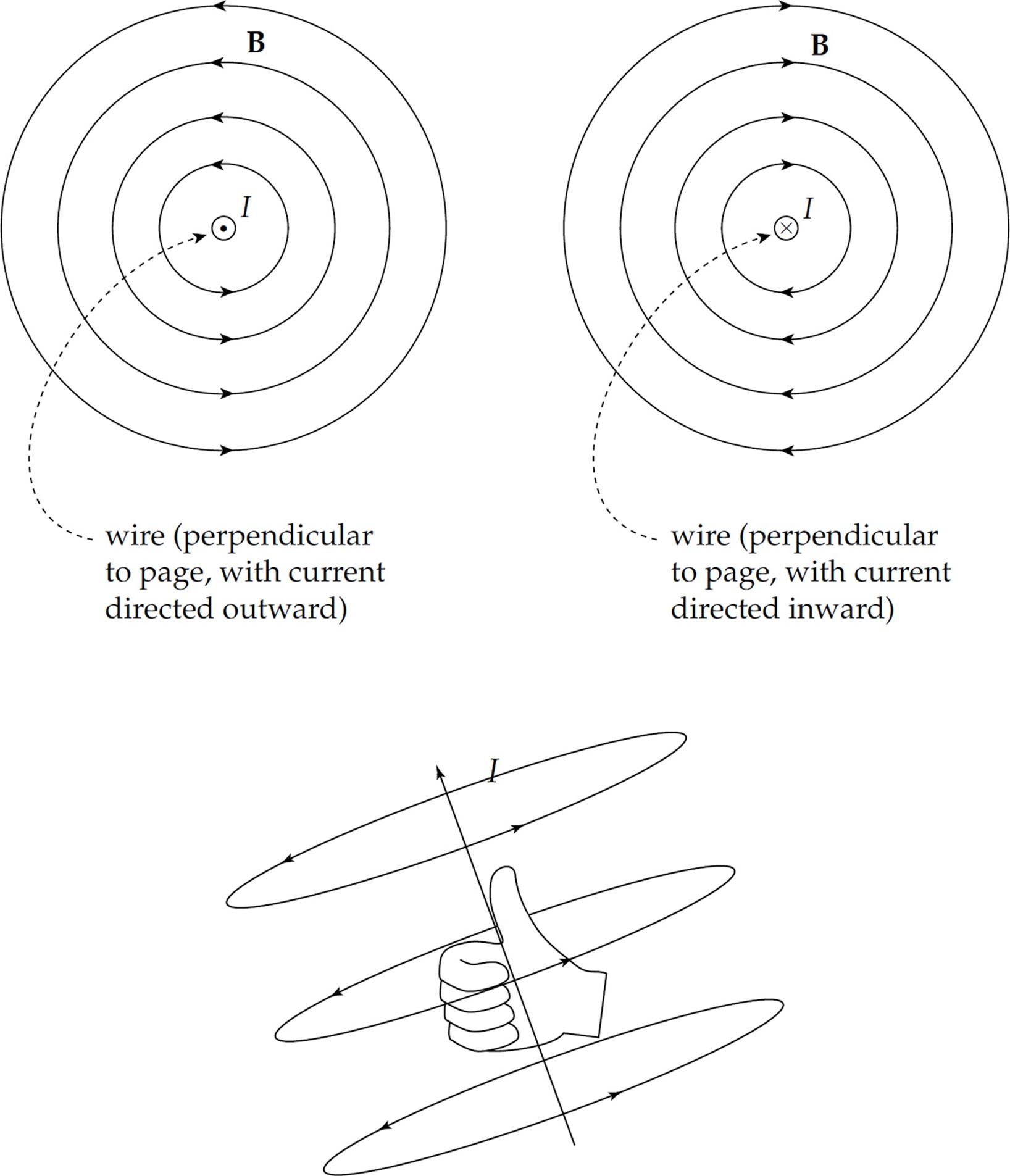
The magnetic field lines are actually circles whose centers are on the wire. The direction of these circles is determined by a variation of the right-hand rule. Imagine grabbing the wire in your right hand with your thumb pointing in the direction of the current. Then the direction in which your fingers curl around the wire gives the direction of the magnetic field line.
Example 8 The diagram below shows a proton moving with a speed of 2 × 10⁵ m/s, initially parallel to, and 4 cm from, a long, straight wire. If the current in the wire is 20 A, what’s the magnetic force on the proton?
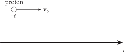
Solution. Above the wire (where the proton is), the magnetic field lines generated by the current-carrying wire point out of the plane of the page, so v0 × B points downward. Since the proton’s charge is positive, the magnetic force FB = q(v0 × B) is also directed down, toward the wire.
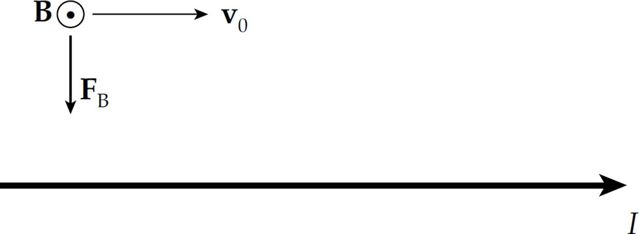
The strength of the magnetic force on the proton is

Example 9 The diagram below shows a pair of long, straight, parallel wires, separated by a small distance, r. If currents I1 and I2 are established in the wires, what is the magnetic force per unit length they exert on each other?

Solution. To find the force on Wire 2, consider the current in Wire 1 as the source of the magnetic field. Below Wire 1, the magnetic field lines generated by Wire 1 point into the plane of the page. Therefore, the force on Wire 2, as given by the equation FB2 = I2(ℓ2 × B1), points upward.
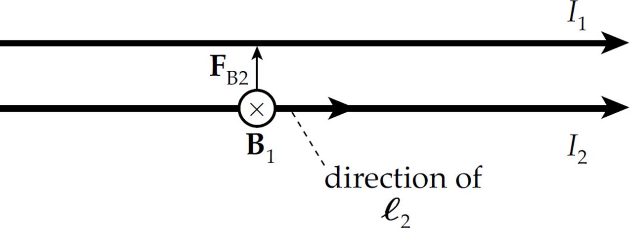
The magnitude of the magnetic force per unit length felt by Wire 2, due to the magnetic field generated by Wire 1, is found this way:

By Newton’s third law, this is the same force that Wire 1 feels due to the magnetic field generated by Wire 2. The force is attractive because the currents point in the same direction; if one of the currents were reversed, then the force between the wires would be repulsive. (And we don’t mean gross repulsive, we mean physics-style repulsion, opposing in direction.)
The Magnetic Field of a Solenoid
Imagine taking a long piece of wire and winding it in a helix around the length of a hollow tube; this is a solenoid. Let N be the total number of turns and L the length of the solenoid; then the number of turns per unit length is N/L, which we’ll call n. If a current I is established in the wire, then a magnetic field is generated in the space that surrounds the solenoid. If the solenoid is much longer than it is wide, then the magnetic field inside will be parallel to the central axis and nearly uniform. The strength of the field inside is given by the equation
![]()
So, the magnetic field inside a solenoid can be increased either by winding the wire more tightly (to increase n) or by increasing the current.
Note that there is a
difference between B
created externally versus
being self-generated. The
forces from the self-
generated field will cancel
out and thus the field does
not need to be considered.
Example 10 A tightly wound solenoid has a length of 30 cm, a diameter of 2 cm, and contains a total of 10,000 turns. If it carries a current of 5 A, what’s the magnitude of the magnetic field inside the solenoid?
Solution. Since the solenoid is so much longer than it is wide, the equation B = µ0nI can be used to calculate the field inside:

THE BIOT–SAVART LAW
In this section, you’ll learn one way to determine the magnetic field created by an electric current. Let’s say we want to determine the magnitude and direction of the magnetic field, at Point P, created by the current I in the diagram below.
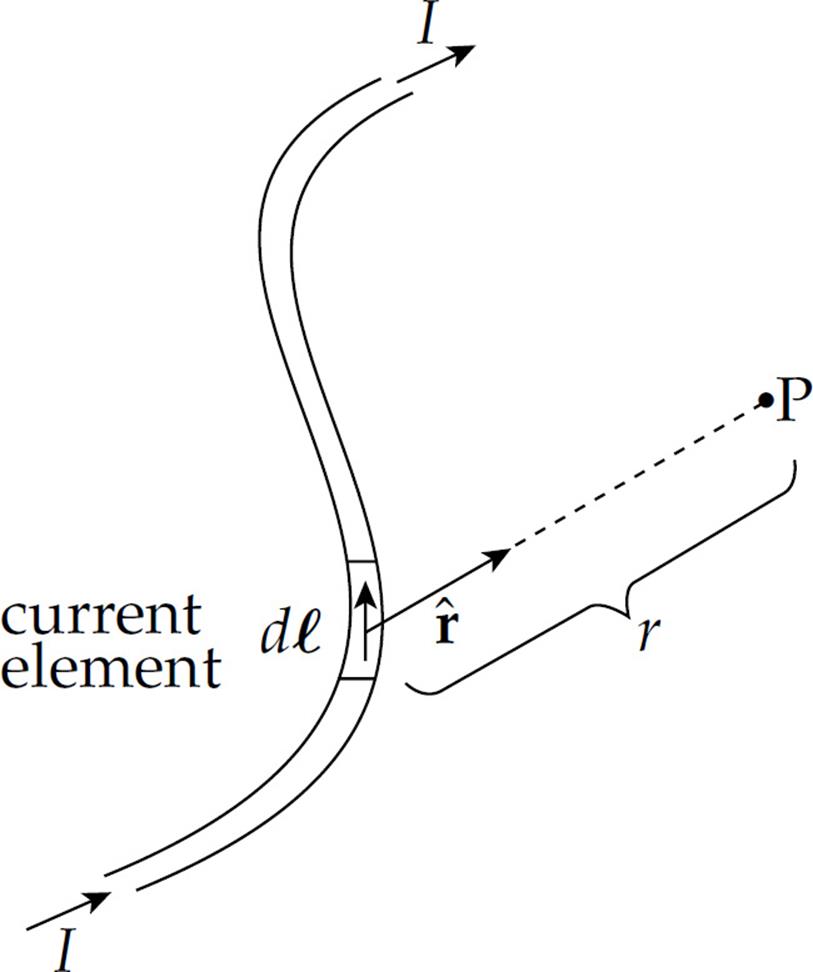
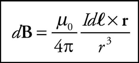
Consider a small section of the current, an infinitesimal section of length dℓ, and assign it the direction of the current so we obtain a current element, dℓ. Let r be the position vector from the current element to the Point P, and form the unit vector ![]() = r/r. Then the magnitude and direction of the magnetic field at P, due to the current element is
= r/r. Then the magnitude and direction of the magnetic field at P, due to the current element is

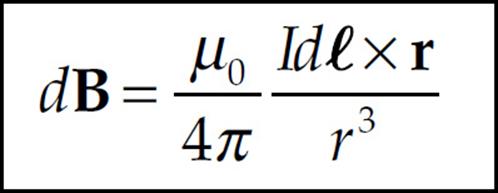
This is called the Biot–Savart law. By adding all the contributions to the magnetic field, we can get the total magnetic field due to the entire current. On the equation sheet for the free-response section, this information will be represented as follows:
Example 11 Use the Biot–Savart law to show that the magnetic field due to an infinitely long straight wire carrying a current I is given by the equation B = (µ0/2π)I/R, where R is the distance from the wire. You should use the integration formula

Solution. Refer to the diagram below:

The direction of dℓ × ![]() is out of the plane of the page (because P is above the wire). The contribution from the current element to the total magnetic field at P is given by the Biot–Savart law:
is out of the plane of the page (because P is above the wire). The contribution from the current element to the total magnetic field at P is given by the Biot–Savart law:

From the diagram, we see that  , so
, so

and, integrating along the entire wire, we get:

Example 12 A circular loop of wire has radius R. If the loop carries a current I, what’s the magnetic field created at the center of the loop?
Solution.
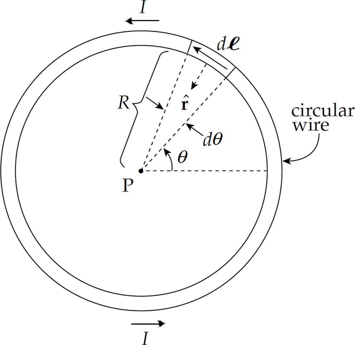
Every current element dℓ is perpendicular to ![]() , and r = R, so the Biot–Savart law gives us:
, and r = R, so the Biot–Savart law gives us:

Writing dℓ = R dθ, we integrate around the circle to get

If the current is counterclockwise (as shown), then dℓ × ![]() , and the magnetic field, points out of the plane of the page, but if the current is clockwise, the magnetic field at the center points into the page.
, and the magnetic field, points out of the plane of the page, but if the current is clockwise, the magnetic field at the center points into the page.
AMPERE’S LAW
In Chapter 11, we learned about Gauss’s law, which can be used to calculate the electric field due to a configuration of electric charges. Gauss’s law says that the electric flux through a closed Gaussian surface (which is actually the integral of E · dA over the area of the surface) is equal to a constant (1/ε0) times the total electric charge enclosed by the surface.
There’s an analogous law for calculating the magnetic field due to a configuration of electric currents. This law says that the integral of B · ds around a closed loop (called an Amperian loop) is equal to a constant (µ0) times the total current that passes through the loop:

This is Ampere’s law and we’ll use it to find the magnetic field at points on an Amperian loop surrounding the source current. (The circle on the integral sign in Ampere’s law emphasizes that the integral must always be taken around a closed path.)
Example 13 Use Ampere’s law to show that the magnetic field due to an infinitely-long straight wire carrying a current I is given by the equation B = (µ0/2π)I/R, where R is the distance from the wire.
Solution. When we did this in Example 11 (using the Biot–Savart law), we ran into a messy integral. Using Ampere’s law will be much easier. First,
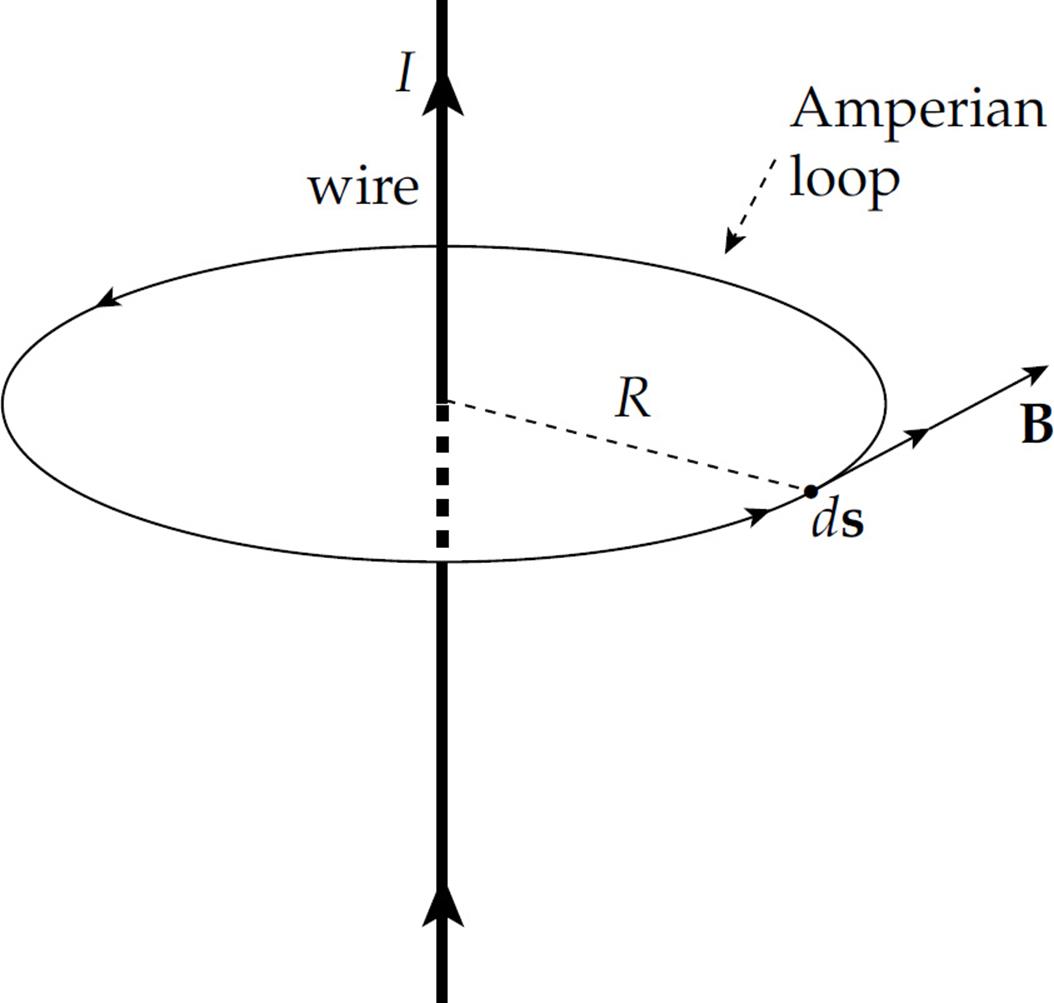
The magnetic field must have the same magnitude at every point on the Amperian circle, and the direction of the field must always be perpendicular to the circle (which means it points radially away from or toward the wire) or always tangent to the circle. We can rule out the first case in two ways: (1) Magnetic field lines always form closed curves that encircle the current that generates them; (2) If B were perpendicular to the Amperian circle, then B · ds would be zero everywhere along the circle, so Ampere’s law would give 0 = µ0I, a contradiction. So B must be tangent to the Amperian circle.
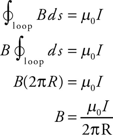
Since B has constant magnitude on the circle and is always parallel to ds (which is a small section of the Amperian loop),
B · ds = B ds cos θ = B ds
The current that passes through the loop is I, so Ampere’s law gives us
Example 14 The figure below is a cut-away view of a long coaxial cable that’s composed of a solid cylindrical conductor (of radius R1) surrounded by a thin conducting cylindrical shell (of radius R2).
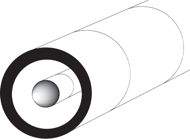
The inner cylinder carries a current of I1 and the outer cylindrical shell carries a smaller current of I2 in the opposite direction. Use Ampere’s law to find the magnitude of the magnetic field (a) in the space between the inner cylinder and the shell, and (b) outside the outer shell.
Solution.
(a) Construct an Amperian loop of radius r in the space between the solid cylinder and the outer shell. The magnetic field must be of constant magnitude along (and tangent to) this loop.
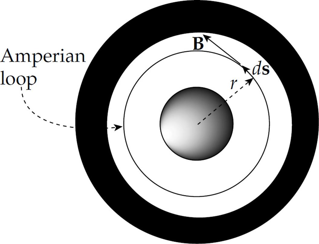
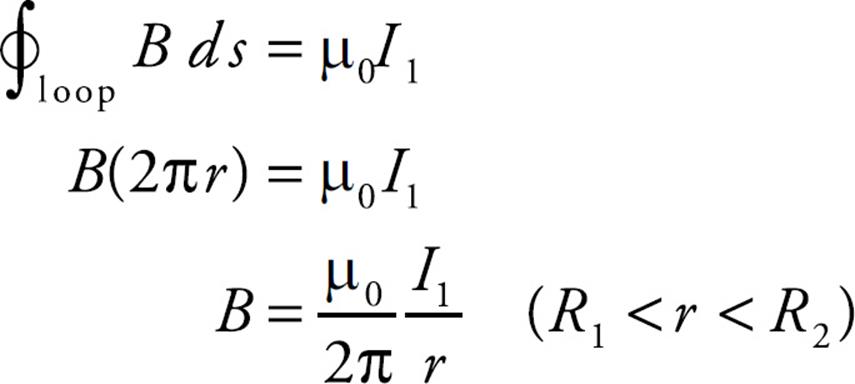
The only current that passes through the loop is I1 (the current I2 in the outer shell does not pierce the interior of the Amperian loop), so Ampere’s law gives us:
(b) Now construct an Amperian loop that encircles the entire cable.

Unlike in the loop constructed in part (a), both currents pass through this loop. If they had the same direction, we’d add them to get the total current, but since the currents here have opposite directions, the net current through the loop is I1 – I2. Ampere’s law then gives us:
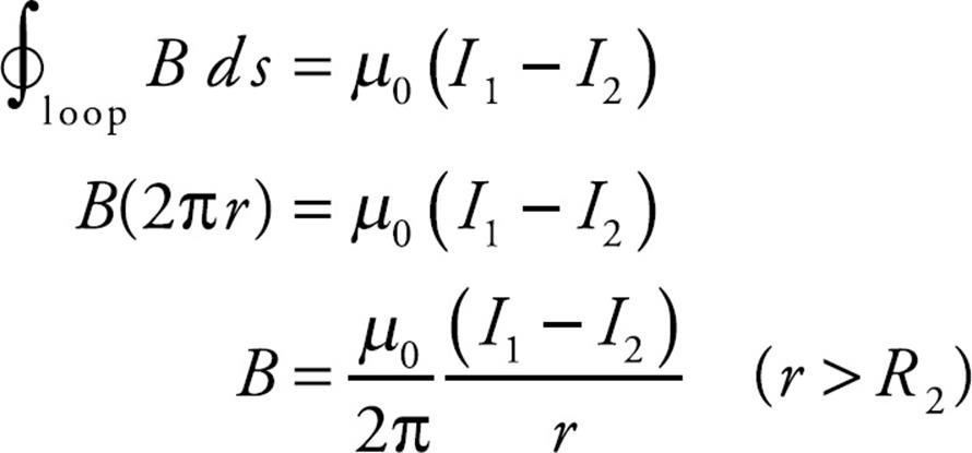
Note that if I1 = I2, then the magnetic field outside the cable is zero.
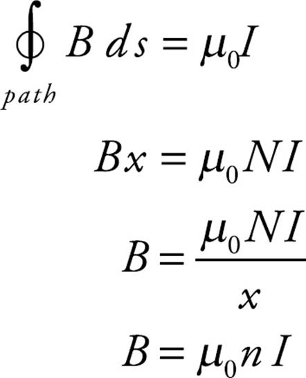
Example 15 A tightly wound solenoid with n coils per length has a current I running through it. Use Ampere’s law to show the magnetic field inside this ideal solenoid is given by the equation, B = µonI.
Solution.
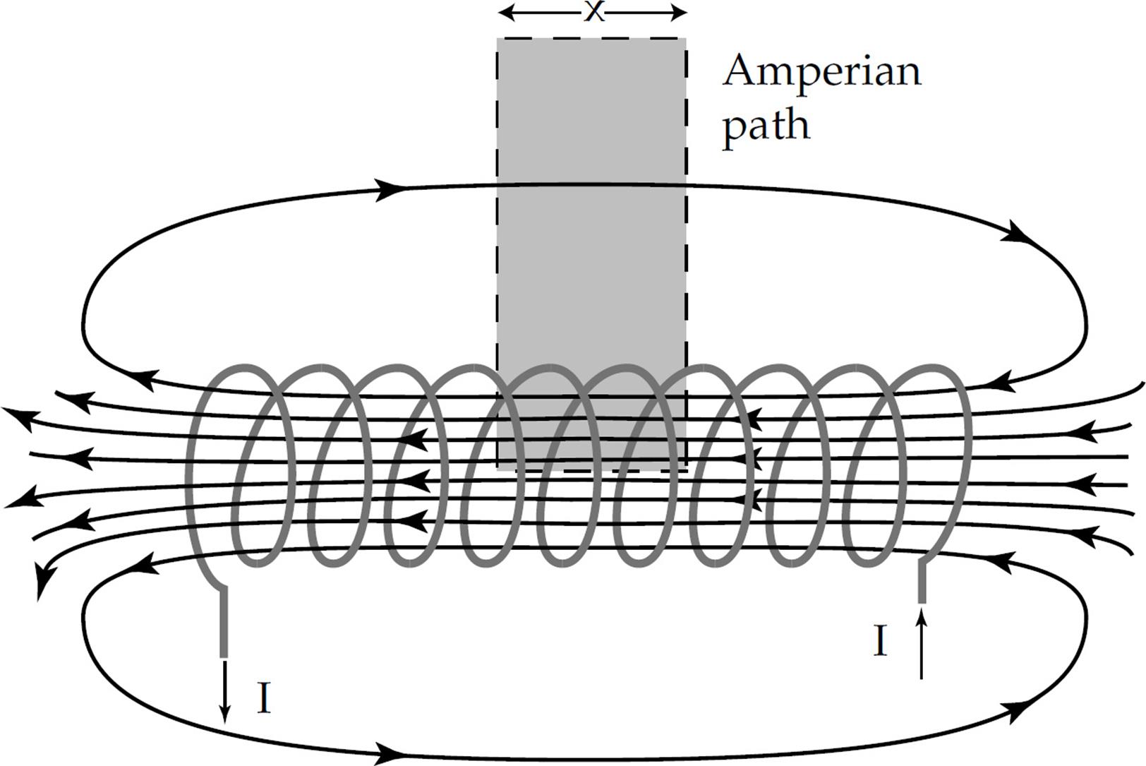
Consider the diagram above. The two vertical sections of the Amperian path do not matter because the path is perpendicular to the magnetic field (remember Ampere’s law is a dot product for B · ds). The top section of the path is approximated as zero for an ideal solenoid because the field is not weak outside a tightly wound solenoid. Therefore, the only part of the path we will use is the length x inside of the solenoid. We will assume N total coils pass through the shaded region of our Amperian path.
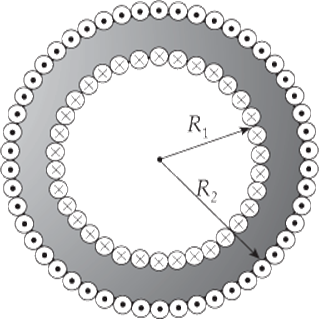
Example 16 The figure below is a cross section of a toroidal solenoid (a solenoid bent into a doughnut shape) of inner radius R1 and outer radius R2. It consists of N windings, and the wire carries a current I. What’s the magnetic field in each of the following regions?
(a) r < R1
(b) R1 < r < R2
(c) r > R2
Solution.
(a) If we construct a circular Amperian loop of radius r < R1, then no current will pass through it.
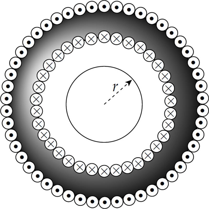
Since  and Ithrough loop = 0, Ampere’s law immediately tells us that B = 0 in this region (the hole of the doughnut).
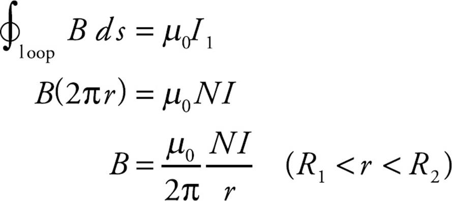
(b) Construct a circular Amperian loop of radius r such that R1 < r < R2. Each of the N windings that brings current into the plane of the page passes through the loop, but the N windings that bring current out of the plane of the page do not pass through the loop.
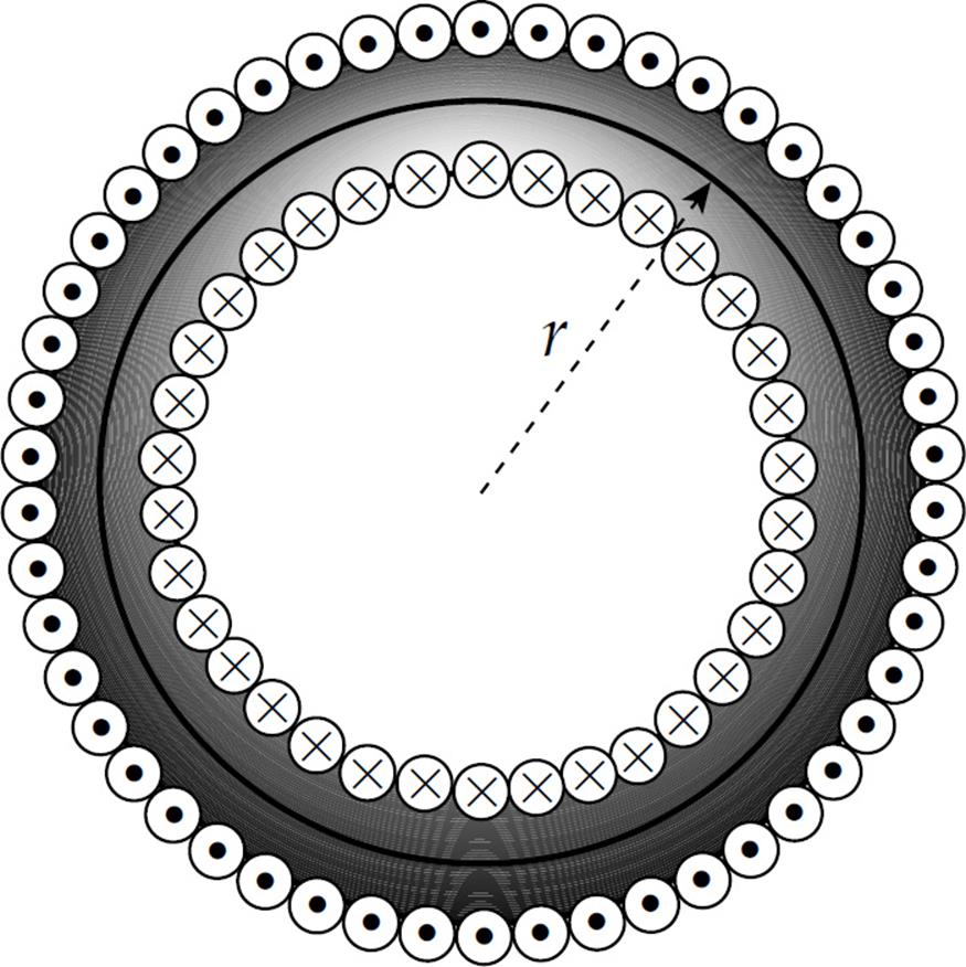
So, the net current through the loop is NI, and Ampere’s law gives us:
(c) Construct a circular Amperian loop of radius r > R2.
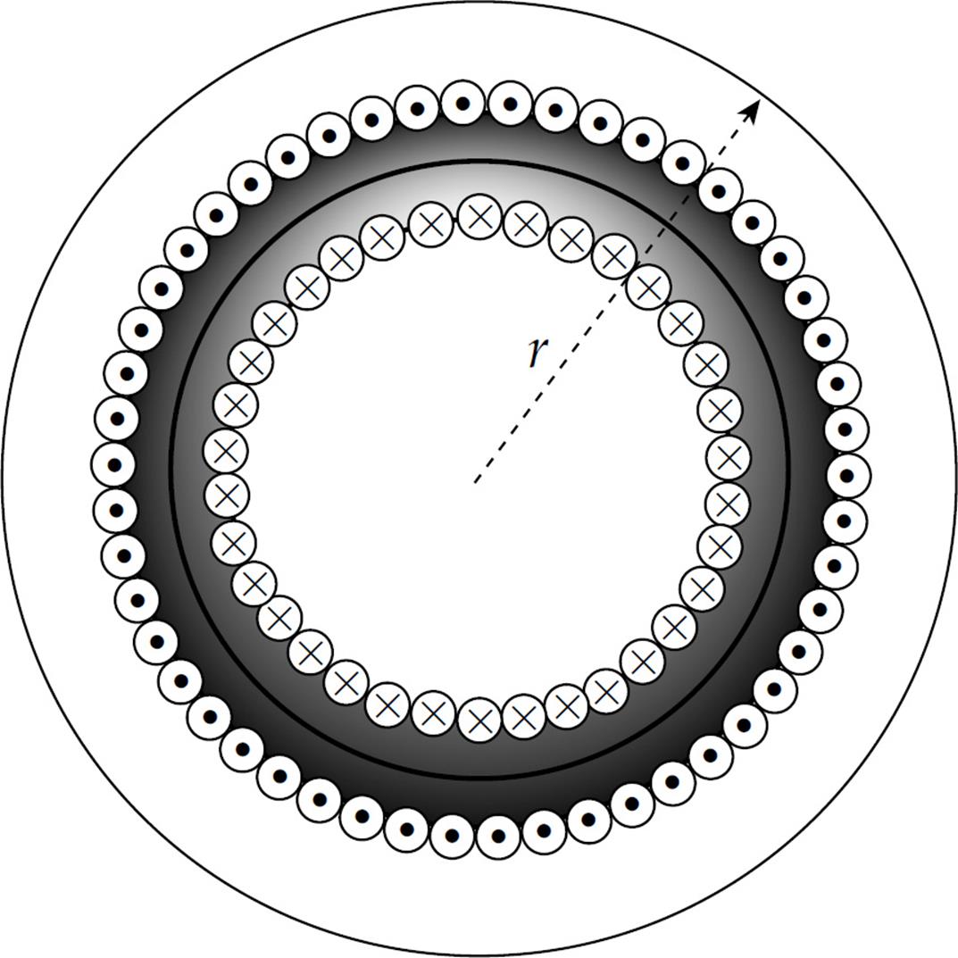
For every current contribution of I punching upward through the loop, there is an equal current punching downward through the loop, so the net current through the loop is zero, and B = 0 in this region.
Note that the results of
this example show that for
an ideal toroidal solenoid,
the magnetic field is contained
within the space
enclosed by the windings.
CHAPTER 14 REVIEW QUESTIONS
The answers and explanations can be found in Chapter 16.
Section I: Multiple Choice
1. Which of the following is/are true concerning magnetic forces and fields?
I. The magnetic field lines, due to a current-carrying wire, radiate away from the wire.
II. The kinetic energy of a charged particle can be increased by a magnetic force.
III. A charged particle can move through a magnetic field without feeling a magnetic force.
(A) I only
(B) II and III only
(C) I and II only
(D) III only
(E) I and III only
2. The velocity of a particle of charge +4.0 × 10⁻⁹ C and mass 2 × 10⁻⁴ kg is perpendicular to a 0.1-tesla magnetic field. If the particle’s speed is 3 × 10⁴ m/s, what is the acceleration of this particle due to the magnetic force?
(A) 0.0006 m/s2
(B) 0.006 m/s2
(C) 0.06 m/s2
(D) 0.6 m/s2
(E) None of the above
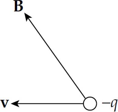
3. In the figure below, what is the direction of the magnetic force FB?
(A) To the right
(B) Downward, in the plane of the page
(C) Upward, in the plane of the page
(D) Out of the plane of the page
(E) Into the plane of the page
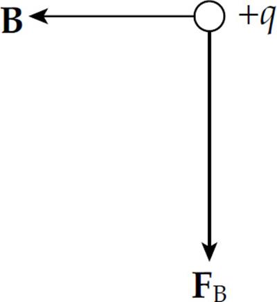
4. In the figure below, what must be the direction of the particle’s velocity, v?
(A) To the right
(B) Downward, in the plane of the page
(C) Upward, in the plane of the page
(D) Out of the plane of the page
(E) Into the plane of the page
5. Due to the magnetic force, a positively charged particle executes uniform circular motion within a uniform magnetic field, B. If the charge is q and the radius of its path is r, which of the following expressions gives the magnitude of the particle’s linear momentum?
(A) qBr
(B) qB/r
(C) q/(Br)
(D) B/(qr)
(E) r/(qB)
6. A straight wire of length 2 m carries a 10-amp current. How strong is the magnetic field at a distance of 2 cm from the wire?
(A) 1 × 10⁻⁶ T
(B) 1 × 10⁻⁵ T
(C) 2 × 10⁻⁵ T
(D) 1 × 10⁻⁴ T
(E) 2 × 10⁻⁴ T
7. Two long, straight wires are hanging parallel to each other and are 1 cm apart. The current in Wire 1 is 5 A, and the current in Wire 2 is 10 A, in the same direction. Which of the following best describes the magnetic force per unit length felt by the wires?
(A) The force per unit length on Wire 1 is twice the force per unit length on Wire 2.
(B) The force per unit length on Wire 2 is twice the force per unit length on Wire 1.
(C) The force per unit length on Wire 1 is 0.0003 N/m, away from Wire 2.
(D) The force per unit length on Wire 1 is 0.001 N/m, toward Wire 2.
(E) The force per unit length on Wire 1 is 0.001 N/m, away from Wire 2.
8. In the figure below, what is the magnetic field at the Point P, which is midway between the two wires?

(A) 2µ0I/(πd), out of the plane of the page
(B) 2µ0I/(πd), into the plane of the page
(C) µ0I/(2πd), out of the plane of the page
(D) µ0I/(2πd), into the plane of the page
(E) Zero
9. How many windings must a solenoid of length 80 cm have in order to establish a magnetic field of strength 0.2 T inside the solenoid, if it carries a current of 20 amps?
(A) 1,000
(B) 6,400
(C) 10,000
(D) 32,000
(E) 64,000
10. The value of  · ds along a closed path in a magnetic field B is 6.28 × 10⁻⁶ T · m. What is the total current that passes through this closed path?
(A) 0.1 A
(B) 0.5 A
(C) 1 A
(D) 4 A
(E) 5 A
Section II: Free Response
1. The following diagram shows a simple mass spectrograph. It consists of a source of ions (charged atoms) that are accelerated (essentially from rest) by the voltage V and enter a region containing a uniform magnetic field, B. The polarity of V may be reversed so that both positively charged ions (cations) and negatively charged ions (anions) can be accelerated. Once the ions enter the magnetic field, they follow a semicircular path and strike the front wall of the spectrograph, on which photographic plates are constructed to record the impact.
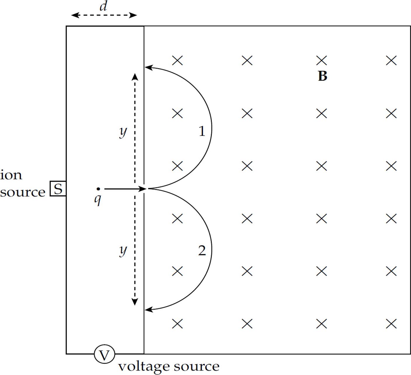
(a) What is the acceleration of an ion of charge q just before it enters the magnetic field?
(b) Find the speed with which an ion of charge q enters the magnetic field.
(c) (i) Which semicircular path, 1 or 2, would a cation follow?
(ii) Which semicircular path, 1 or 2, would an anion follow?
(d) Determine the mass of a cation entering the apparatus in terms of y, q, B, and V.
(e) Once a cation of charge q enters the magnetic field, how long does it take to strike the photographic plate?
(f) What is the work done by the magnetic force in the spectrograph on a cation of charge q?
2. A wire of diameter d and resistivity ρ is bent into a rectangular loop (of side lengths a and b) and fitted with a small battery that provides a voltage V. The loop is placed at a distance c from a very long, straight wire that carries a current I in the direction indicated in the diagram.
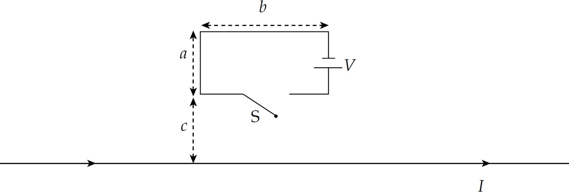
(Express all answers in terms of a, b, c, d, ρ, V, I, m, B, x, and fundamental constants.)
(a) When the switch S is closed, find the current in the rectangular loop.
(b) What is the magnetic force (magnitude and direction) exerted on the loop by the long, straight wire?
(c) The wire of the rectangular loop is then reshaped into a circle. What will be the radius of the circular loop?
(d) If the loop constructed in part (c) were then threaded around the long, straight wire (so that the straight wire passed through the center of the circular loop), what would be the magnetic force on the loop now?
(e) In the following diagram, two fixed L-shaped wires, separated by a distance x, are connected by a wire that’s free to slide vertically.
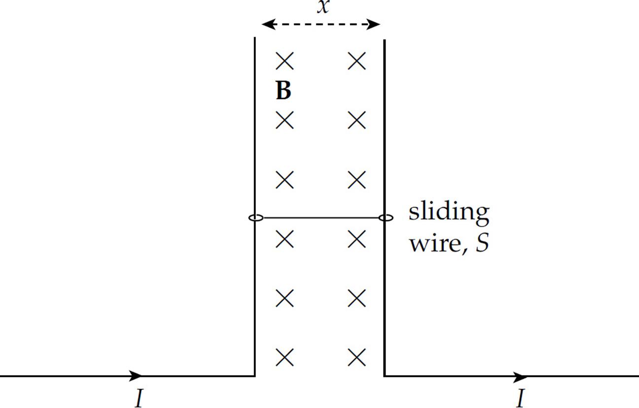
The mass of the sliding wire, S, is m. If the sliding wire S crosses a region that contains a uniform magnetic field B, how much current must be carried by the wire to keep S from sliding down (due to its weight)?
3. The figure below shows two long, straight wires connected by a circular arc of radius x that subtends a central angle φ. The current in the wire is I.
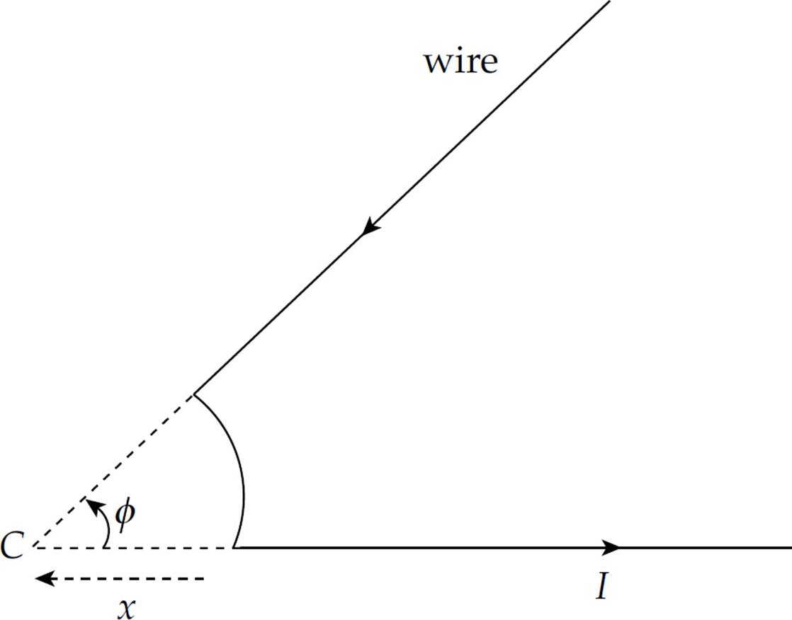
(a) Find the magnetic field (magnitude and direction) created at Point C. Write your answer in terms of x, φ, I, and fundamental constants.
(b) A particle of charge +q is placed at Point C and released. Find the magnetic force on the particle.
(c) A second long, straight wire is set up perpendicular to the plane of the page through C, carrying the same current, I (directed out of the page), as the wire pictured in the diagram. Determine the magnetic force per unit length between the wires.
4. For a conducting rod that carries a current I, the current density is defined as the current per unit area: J = I/A.
Part 1. A homogeneous cylindrical rod of radius R carries a current whose current density, J, is uniform (constant); that is, J does not vary with the radial distance, r, from the center of the rod.
(a) Determine the total current, I, in the rod.
(b) Calculate the magnitude of the magnetic field for
(i) r < R
(ii) r > R, writing your answers in terms of r, R, I, and fundamental constants.
Part 2. A nonhomogeneous cylindrical rod of radius R carries a current whose current density, J, varies with the radial distance, r, from the center of the rod according to the equation J = σ r, where σ is a constant.
(c) What are the units of σ ?
(d) Determine the total current, I, in the rod.
(e) Calculate the magnitude of the magnetic field for
(i) r < R
(ii) r > R, writing your answers in terms of r, R, and I.
Summary
Magnetic Force
- When a charged particle moves through a magnetic field it will experience a force if the velocity is not parallel with the magnetic field. The force is given by the following equation:

- Notice that this is a cross product of the velocity and the magnetic field vectors, so the directions of the force can be obtained using the right-hand rule from Chapter 3.
- Since the force will always be perpendicular to the velocity, the force will not change the speed of the particle, it will only change its direction. This fact can be used to cause the particle to travel in a circle.
- A current-carrying wire will also experience a force when it is in a magnetic field because the wire has a moving charge within it. The force is given by the following equation:
FB = I(ℓ × B)
Magnetic Fields
- One can calculate the magnetic field created by a current using the Biot-Savart law and Ampere’s law. Ampere’s law is easier to use, but the magnetic field created by the current needs to be more symmetric for it to be used.
- The Biot-Savart law states

- Ampere’s law is

- Use Ampere’s law to find the magnetic field due to the following current-carrying devices: long wires, coaxial cables, solenoids, and toroids.
- The magnitude of the magnetic field at a distance r from a long, straight wire is
 .
.