Physical Chemistry Essentials - Hofmann A. 2018
Solutions of Electrolytes
4.2 Electrochemical Reactions
After having introduced some fundamental concepts and quantities of electricity, we will now consider their applications in a chemical context. Electrochemical reactions can proceed in systems when a suitable electric potential difference ΔE is applied. In this case, electric energy is converted into chemical energy. Such cells are called electrolytic cells.
Alternatively, chemical reactions may result in the build-up of an electric potential difference, i.e. chemical energy is converted into electric energy. These cells are called galvanic cells.
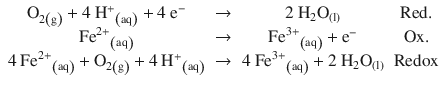
Conceptually, an electrochemical cell is separated into two half-cells, separating the oxidation and the reduction processes. The two electrochemical half reactions oxidation and reduction are combined into a net reaction, called Redox reaction. For example:
Fe2+ ions in aqueous solution are unstable and oxidised readily to Fe3+ by oxygen from ambient air:
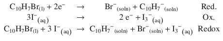
Bromo-naphthalene is a component of battery paste and used as an insulating liquid in graphite paste electrodes. It can undergo a Redox reaction with iodide in lithium-iodide batteries:
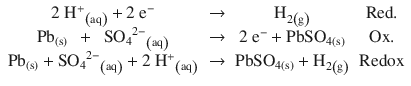
The lead acid battery (invented by Gaston Planté in 1859, and still in use today as car battery) may produce H2 gas when the battery is deeply or rapidly discharged:
4.2.1 Galvanic and Electrolytic Cells
If two half-cells are combined where the different chemical reactions give rise to an electric potential difference, the resulting electrochemical cell is called a galvanic cell. A prominent example is the so-called Daniell element shown in Fig. 4.4, left panel. Here, the spontaneously proceeding Redox reaction converts chemical into electric energy; this constitutes the working principle of batteries.
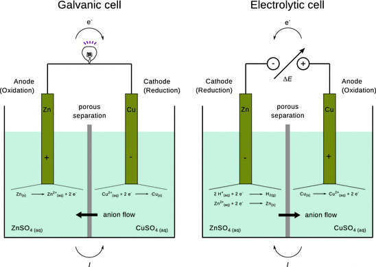
Fig. 4.4
Illustration of the processes in a galvanic cell (left panel) and electrolytic cell (right panel), using the Daniell element which consists of Zn/ZnSO4 and Cu/CuSO4 half-cells. At the cathode of the electrolytic cell, one would expect hydrogen gas evolving, as the H+/H2 Redox potential is 0.76 V in favour as compared to Zn2+/Zn (see Table 4.3). However due to the hydrogen overpotential, H2 generation is hindered and thus elementary zinc is deposited
According to Faraday, the definition of anode and cathode depend on charge and discharge. The anode is the electrode to which anions flow. The anode possesses positive potential and thus gives rise to an oxidation reaction, where suitable species (elementary zinc in Fig. 4.4, left panel) deposit their electrons onto the electrode. In contrast, the cathode is the electrode attracting cations; it is the electrode with negative potential. Here, suitable species (Cu2+ ions in Fig. 4.4, left panel) are reduced by receiving electrons from the electrode.
In an electrolytic cell, a chemical reaction is forced to occur due to current flowing through a cell. An electric potential needs to be applied externally (Fig. 4.4, right panel), causing conversion of electric to chemical energy. Both electrodes are placed in a container that contains the solution of molten or dissolved electrolyte. The external power supply provides the electrons. They enter the electrolyte solution through the cathode (negative potential) and leave through the anode (positive potential).
At the anode, which has a lack of electrons due to the positive potential, electrons are removed from suitable substances at the anode surface—an oxidation occurs. The cathode, in contrast, possesses a surplus of electrons due to its negative potential. Here, electrons will be transferred onto suitable substances—this is a reduction.
Figure 4.4 contrasts the two different electrochemical cell types by using the same element, i.e. a Zn/ZnSO4 and a Cu/CuSO4 half-cell (the Daniell element). Of course, a galvanic cell is not supposed to be used as an electrolytic cell, hence the right panel of Fig. 4.4 is for illustration of the concept only. Note that when the Daniell element is inverted to become an electrolytic cell, the reduction at the anode does not deposit elementary zinc at the electrode, but rather produces hydrogen gas from water, since the reduction of hydrogen is electrochemically more favourable (see Sect. 4.2.8).
In technical applications, electrolytic cells are not constructed as two physical half-cells, but one cell which comprises the molten or dissolved electrolyte (e.g. CuSO4) and electrodes made of the corresponding metal (Cu). In such cells, solid metal (Cu) will be deposited on the cathode; impurities either remain in solution or collect as an insoluble sludge. This process is known as electrolytic refinement and used to obtain metals of highest purity.
Rechargeable Batteries
Rechargeable batteries, such as e.g. NiMH cells or lead-acid batteries, act as galvanic cells when discharging, i.e. they convert chemical energy to electrical energy, and as electrolytic cells when being charged. In the charging process, electrical energy is converted to chemical energy.
In summary, the reaction happening at the anode is oxidation and that at the cathode is reduction. Electrons are supplied by the chemical species getting oxidised at the anode, leave the electrolyte solution through the anode and enter the electrolyte solution in the other half-cell through the cathode. In this circuit, the anode therefore has a positive potential, and the cathode a negative potential.
Overpotential
In the electrolytic cell in Fig. 4.4, the electrodeposition of zinc will occur in competition with the generation of hydrogen. Whereas thermodynamically the reduction of hydrogen is favoured (the Redox potential of the H+/H2 element is higher than that of the Zn2+/Zn element, so less energy is required to push electrons into the H+/H2 process), the Zn2+ reduction process is kinetically favoured. By way of steric hindrance, it is difficult for hydrogen atoms to move around on the surface of the zinc electrode to eventually form H2 molecules. This difficulty varies for different metal surfaces. In electrochemical cells, this phenomenon gives rise to an overpotential which needs to be considered when designing galvanic and, importantly, electrolytic cells. Processes such as electrolytic refinement of metals, which require large quantities of electricity, need to be optimised for power consumption and thus consider overpotentials.
4.2.2 The Faraday Laws
Of great importance for industrial applications of electrochemical processes as well as for the development of electrochemistry in general have been the Faraday laws, which Michael Faraday developed in 1834 (Ehl and Ihde 1954).
Consider the electrolytic cell illustrated in the right panel of Fig. 4.4 in the previous section. At the cathode, hydrogen gas is produced in an electrochemical reduction, powered by the application of an electrochemical potential to the element. The gas leaving the half-cell can be captured and thus its volume can be determined. The quantity of gas produced will be dependent on the current flowing through the cell, i.e. the quantity of electrical charge passing through.
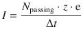
This is summarised in Faraday’s first law of electrolysis:
The mass of a substance altered at an electrode during electrolysis is directly proportional to the quantity of electricity transferred at that electrode.
![]()
(4.19)
If one was to serially combine several different electrolytic cells in each of which a different elementary substance is produced at the cathode, there will be a particular mass of that element generated in the individual cells.
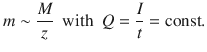
Faraday’s second law of electrolysis states:
For a given quantity of electric charge, the mass of a deposited/generated elementary substance is proportional to the molar mass of that substance divided by the change in oxidation state (i.e. in most cases the charge of the cation in the electrolyte).
(4.20)
Applying Eq. 4.20 to two different electrolytic cells 1 and 2 through which the same amount of charge Q is passed, one obtains the following mass ratio of generated elementary substances:
(4.21)
4.2.3 The Electromotive Force
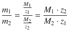
We consider a galvanic cell where two half-cells are combined to generate an electric potential difference ΔE. This potential difference arises from the different chemical potentials in the two half-cells that causes electrons to flow from one half-cell to the other. It is thus called the electromotive force (e.m.f.) of the cell (see Fig. 4.5). Importantly, the value of the e.m.f. can only be established if a negligible current is drawn from the cell (which is a requirement for any Volt meter used to determine the voltage when placed in parallel to a resistor). If the two half-cells were connected by a short circuit (i.e. the external resistance would be zero, R ext = 0), then current flow would be maximised and there was no potential difference (ΔE = 0). If the two half-cells are connected by a Volt meter which possesses a very large resistance, then the current I is negligible and the potential difference ΔE is maximised. This is the desired configuration, as any current flowing between the two half-cells is the consequence of a proceeding Redox reaction and thus inevitably results in a lowering of the potential difference.
Fig. 4.5
The convention for determining the electromotive force of an electrochemical cell; e.m.f. = ΔE = E right−E left
The combination of two half-cells is denoted by separating the electrode material and electrolyte solutions of the left and right half-cells by vertical lines. For example, the Daniell element, which we have introduced in Sect. 4.2.1, is written as:
![]()
The above cell denotes a zinc electrode immersed in an electrolyte solution of 1 M aqueous ZnSO4 as the left cell and a copper electrode immersed in 1 M aqueous CuSO4 solution as the right cell.
Importantly, the e.m.f. (or electric potential difference) is by convention defined as
![]()
(4.22)
with E right and E left being the electric potentials of the right and left half-cells, respectively. In the example above, the right half-cell consisting of the system:
![]()
possesses the higher potential and therefore pulls electrons from the left half-cell which consists of the system:
![]()
Therefore, the spontaneously proceeding reactions in this electrochemical cell will consist of the reduction of Cu2+ ions and the oxidation of Zn, with the following net reaction:
![]()
![]()
(4.23)
The potential difference between the right and the left half-cell yields the electromotive force of that cell.
Importantly, when the number of electrons consumed or produced in the two half-cells differ, the Redox potentials must not be multiplied. In manipulating potentials, one can only change the signs of the values, not the magnitude. For example, a combination of the hydrogen electrode (see Sect. 4.2.7) with the silver/silver chloride electrode comprises the following reactions:
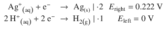
and yields the net spontaneous reaction:
![]()
![]()
The multiplication with factor 2 in above Ag+/Ag reaction only applies to the chemical reaction, not to the Redox potential.
Sacrificial Anodes
The above example has an important application in the protection of active metals that may be subject to corrosion. Consider large metal containers such as hulls of ships, water heaters, pipelines, distribution systems, or metal tanks, all of which are made of metals that could potentially be oxidised (e.g. copper). By combination with a less valuable metal (such as zinc), an electrochemical cell is generated which uses zinc (or any metal alloy with a more negative electrochemical potential than the other metal) as the sacrificial anode. When exposed to environmental processes, the sacrificial anode will be consumed in place of the metal it is protecting. Obviously, these anodes must be periodically inspected and replaced when consumed, in order for the protection to continue.
4.2.4 Concentration Dependence of the Electromotive Force
The electromotive force of a cell arises from spontaneously proceeding reactions in the half-cells. In the half-cell where the oxidation occurs we can formulate the following reaction:
![]()
where ’Red’ denotes a substance to be oxidised (a reducing agent), and ’Ox’ denotes a substance to be reduced (an oxidation agent). The electromotive force arising from this reaction is also called the Redox potential of this ’Red’-’Ox’ pair.
The change in the free energy ΔG of the above reaction represents the electric work the system can provide to the environment:
![]()
(4.24)
We have established earlier that
![]()
(2.10)
(4.3)
If 1 mol charges are passing through, then N passing = n · NA, and thus
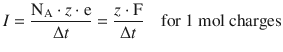
(4.25)
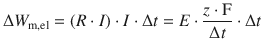
We can then calculate the electric work based on 1 mol passing charges:
![]()
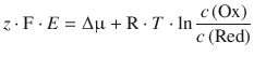
From Eq. 4.15 we know that R ⋅ I = ΔE. ΔE describes the potential difference between two electrodes or half-cells. Since we are here considering just one half-cell (the one where oxidation occurs), we describe an absolute potential E = R ⋅ I, albeit this absolute value will be impossible to determine (see Sect. 4.2.7). Furthermore, using Eq. 4.25 yields:
![]()
(4.26)
Considering the molar Gibbs free energy in Eq. 4.24 allows the following conclusion:
![]()
and we remember that the difference of molar Gibbs free energy is the difference of chemical potential (Eq. 2.67):
![]()
and this difference is the difference between the chemical potential of the oxidised and reduced states of the Redox pair
![]()
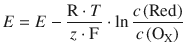
Using Eq. 3.12 (μ = μ— + R ⋅ T ⋅ ln a , and assuming an activity coefficient of γc = 11mol−1 such that a = |c|), this resolves to:
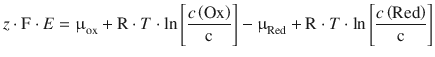
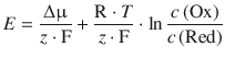
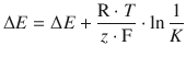
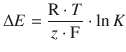
When combining the quotient of constants ![]() into a new constant E — (called the standard e.m.f.) and inverting the argument of the logarithm, we obtain:
into a new constant E — (called the standard e.m.f.) and inverting the argument of the logarithm, we obtain:
(4.27)
This equation is known as the Nernst equation and describes the concentration dependence of the electromotive force, and thus the Redox potential.
The standard electromotive force E — is the standard electrode potential (standard Redox potential) of the ’Red’-’Ox’ pair.
4.2.5 Combination of Two Half-Cells
In Sect. 4.2.3, we have introduced the combination of two half-cells as illustrated by the Daniell element:
![]()
In this formalism, an electrochemical cell is denoted by a series of compartments. It is understood by convention that the electrode potential of the right-hand electrode is higher than that of the left-hand electrode, because the e.m.f. is reported positive in above example, and calculated as
![]()
(4.22)
so if e.m.f. > 0 then E right > E left.
If the cell above had been written in reverse order, then the e.m.f. would be negative:
![]()
Importantly, the electrode with the higher potential is always the one where reduction occurs; the electrode with the lower potential is where oxidation occurs.
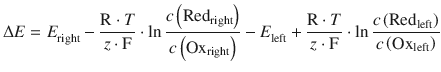
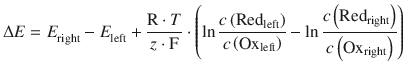
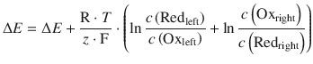
We can re-formulate the above example in a more general fashion, combining a Redox pair in the left half-cell (Redleft, Oxleft) with one in the right half-cell (Redright, Oxright):
![]()
with the following chemical reactions:
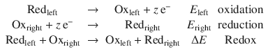
If E right > E left, then electrons will be flowing from the left half-cell to the right half-cell. That means ΔE is positive, and all reactions above will proceed from the left to right.
![]()
(4.22)
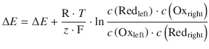
(4.28)
Electromotive Force Under Non-standard Concentrations
We can now consider the Daniell element at varying electrolyte concentrations, and calculate the electromotive force for example under the following conditions:
![]()
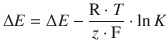
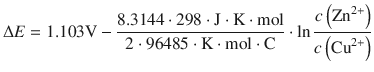
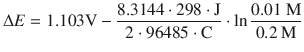
This cell denotes a zinc electrode immersed in an electrolyte solution of 0.01 M aqueous ZnSO4 as the left cell and a copper electrode immersed in 0.2 M aqueous CuSO4 solution as the right cell. The potential difference in this electrochemical cell is now calculated using the Nernst equation 4.28, considering the different concentrations of the electrolytes:
(4.28)
We have previously established the net reaction for this cell in Eq. 4.23, and thus obtain for the standard potential difference of this cell:
![]()
The equilibrium constant K is calculated from the reaction in 4.23 by:

Therefore:
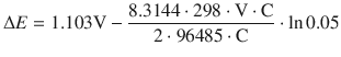
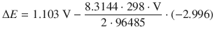
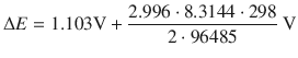
![]()
When the reactants of the cell have reached their equilibrium concentrations, there is no electric current flowing between the two half-cells (such as for example in a flat battery), and ΔE = 0. It then follows that:
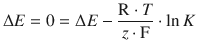
(4.29)
Hence, the standard electrode potential difference ΔE — of an electrochemical cell can be used to determine the equilibrium constant K of the system. The importance of this conclusion is that from a tabulation of standard electrode potentials for individual half-cells (see Sect. 4.2.8), one can derive the standard electrode potentials for the electrochemical cell (i.e. a combination of two half-cells) and predict the value of the equilibrium constant for that system.
Flat Battery
A battery that is exhausted (’flat’) no longer generates an electric current when connected to an external circuit. In this condition, there is no chemical reaction occurring in the combination of the two half-cells, which means that the overall cell reaction is at equilibrium. In equilibrium state, all chemical components are present in their equilibrium concentrations. Therefore, we can state that when the reactants of an electrochemical cell have reached their equilibrium concentrations, the e.m.f. of the cell is zero:
ΔE = 0 for a chemical reaction at equilibrium.
4.2.6 The Thermodynamics of the Electromotive Force
From Sect. 2.2.5, when we discussed the Gibbs free energy of a reaction, we know that
![]()
(2.59)
Also, from Eq. 4.29 in the previous section, we can derive for one half-cell that
![]()
(4.29)
It thus follows that
![]()
(4.30)
Therefore, by measuring the standard electromotive force of an electrochemical half-cell, E —, we can determine the change in the molar Gibbs free energy G m of the underlying reaction.
4.2.7 Reference Electrodes
The electric potential of a half-cell is a potential difference itself, namely between a solid metal (electrode) and the electrolyte solution in which it is immersed. This potential difference is called the electrode potential, and it is physically impossible to measure its value. However, as we have already introduced above, it is possible to measure the difference between the electrode potential of one half-cell when combining it with another half-cell. If one chooses a particular half-cell for reasons of comparison, i.e. a reference cell, then standardised electrode potentials can be measured and tabulated.
In this context, the standard hydrogen electrode has been introduced as the reference standard, whereby the electric potential of a platinum electrode which is exposed to H2 gas with a pressure of pnormal = 1.013 bar at θnormal = 25 °C and immersed into a solution with a(H+) = 1 M is arbitrarily set to E — = 0:
![]()
In order to determine standard electrode (or Redox) potentials, one thus measures the e.m.f. of a cell, in which the concentration of solutions are all 1 M. When determining the standard electrode potentials of any electrode, the standard hydrogen electrode is chosen as the left electrode (see Fig. 4.6).
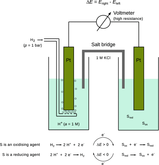
Fig. 4.6
The standard hydrogen electrode and the principle of determining standard electrode potentials
Since the standard hydrogen electrode requires a rather elaborate experimental setup, which proves impractical for many routine laboratory applications, other, more convenient reference electrodes are frequently being used. In principle, any half-cell can be employed which maintains a potential that remains practically unchanged during the course of an electrochemical measurement. One needs to evaluate the standard potential difference of the chosen electrode to the standard hydrogen electrode (see Sects. 4.2.8 and 4.3.1) and correct for this difference, when deploying the chosen electrode in a measurement. The most commonly used reference electrodes in this context are:
✵ Standard hydrogen electrode
![]()
✵ Silver/silver chloride electrode
![]()
✵ Calomel electrode
![]()
Secondary reference electrodes such as the silver/silver chloride or the calomel electrode that are required to maintain a constant potential employ a rather insoluble metal ion salt (AgCl, Hg2Cl2) together with the elementary metal (Ag, Hg). In these cases, the potential difference with respect to the standard hydrogen electrode is not just the standard potential difference of the Redox reaction. Additionally, the transition of the metal ion from the solid to the dissolved state needs to be taken into account as well (see Sect. 4.3.1).
4.2.8 Standard Electrode Potentials
Standard electrode potentials are determined for any electrode by measuring the electromotive force or electric potential difference between that particular electrode and the standard hydrogen electrode. This enables tabulation of standard reduction potentials E — for individual electrodes or half cells. By convention, for such measurements to be conducted under standard conditions, the following parameters need to be ensured:
✵ The molar concentration of each ion needs to be c = 1 M
✵ The pressure of gases needs to be p = pnormal = 1.013 bar
✵ The temperature needs to be θnormal = 25 °C.
Note that the standard reduction potentials indeed refer to ’normal’ conditions. Selected standard electrode (Redox) potentials are given in Table 4.3. When predicting the direction of Redox reactions arising from the combination of half-cells, one needs to remember that the electron flow is from the lower to the higher potential. The electrode with the higher potential is where the reduction occurs (’oxidising’); the electrode with lower potential is where the oxidation occurs (’reducing’).
Table 4.3
Standard reduction potentials for selected half-cells
|
Half-cell |
E — (V) |
|
Most electropositive, most reducing |
|
Li+ (aq) + e− → Li(s) |
−3.04 |
K+ (aq) + e− → K(s) |
−2.92 |
Ca2+ (aq) + 2 e− → Ca(s) |
−2.76 |
Na+ (aq) + e− → Na(s) |
−2.71 |
Mg2+ (aq) + 2 e− → Mg(s) |
−2.38 |
Al3+ (aq) + 3 e− → Al(s) |
−1.66 |
Zn2+ (aq) + 2 e− → Zn(s) |
−0.76 |
Fe2+ (aq) + 2 e− → Fe(s) |
−0.41 |
Cd2+ (aq) + 2 e− → Cd(s) |
−0.40 |
Ni2+ (aq) + 2 e− → Ni(s) |
−0.23 |
Pb2+ (aq) + 2 e− → Pb(s) |
−0.13 |
Fe3+ (aq) + 3 e− → Fe(s) |
−0.04 |
2 H+ (aq) + 2 e− → H2(g) |
0.00 |
Sn4+ (aq) + 2 e− → Sn2+ (aq) |
0.15 |
Cu2+ (aq) + e− → Cu+ (aq) |
0.16 |
AgCl(s) + e− → Ag(s) + Cl− (aq) |
0.22 |
Hg2Cl2(s) + 2 e− → 2 Hg(l) + 2 Cl− (aq) |
0.26 |
Cu2+ (aq) + 2 e− → Cu(s) |
0.34 |
MnO4 − (aq) + 8 H+ (aq) + 5 e− → Mn2+ (aq) + 4 H2O(l) |
1.49 |
H2O2(aq) + 2 H+ (aq) + 2 e− → 2 H2O(l) |
1.78 |
Co3+ (aq) + e− → Co2+ (aq) |
1.82 |
S2O8 2− (aq) + 2 e− → 2 SO4 2− (aq) |
2.01 |
O3(g) + 2 H+ (aq) + 2 e− → O2(g) + H2O(l) |
2.07 |
F2(g) + 2 e− → 2 F− (aq) |
2.87 |
|
Most electronegative, most oxidising |
|
The potential difference of a galvanic cell (one that produces electric power) is calculated as the difference between the electrode with the higher potential (reduction) and that with the lower potential (oxidation): ΔE galv = E red — E ox. Importantly, when the number of electrons consumed or produced in the two half-cells differ, the reduction potentials must not be multiplied
4.2.9 Absolute Electrode Potentials
The determination of absolute electrochemical reduction potentials of isolated half-cells in solution is a challenging task. Therefore, most commonly, reduction potentials are measured relative to other half-cells which establishes a series of reduction potential values that can be ordered from lowest to highest potential. The anchor for this series is the standard hydrogen electrode which has arbitrarily been assigned a value of 0 V.
The availability of an absolute scale would help to bridge a current divide in the electrochemical characterisation of solids, in particular semiconductors, and solutions. When dealing with solid/gas interfaces, it is typically the energy of a free electron in vacuo that is taken as a reference energy. There have thus been numerous efforts to estimate the potential of the standard hydrogen electrode versus a free electron.
A recent approach in this context comprises of the experimental measurement of the energy gained by hydrated metal ions of the type [M(H2O)32]2+ or [M(NH3)6(H2O)55]3+ when capturing an electron, by means of FT/ ICR mass spectrometry (Donald et al. 2008). The reduction of a cluster of hydrated metal ions is accompanied by the loss of water molecules, and the sum of the binding energies of these molecules is correlated with the energy deposited onto the cluster by the gained electron. The energies determined in this fashion represent absolute free energy changes for the reduction of a metal cluster, ΔG abs. These absolute values can be compared to the relative free energy changes ΔG rel measured for the metal clusters by using the conventional reference half-cell methodology (Fig. 4.7). The linear correlation obtained allows for conversion of relative into absolute reduction potentials, and also allows provides an estimate of the absolute reduction potential of the standard hydrogen electrode which is about 4.2 ± 0.4 V (Donald et al. 2008).
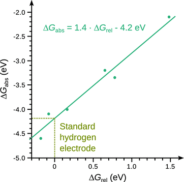
Fig. 4.7
Absolute electrode potentials as determined by Evan Williams and colleagues (Donald et al. 2008)
4.2.10 External Potential Difference
As we have introduced in Sect. 4.2.1, when combining two half-cells into an electrochemical cell, that cell can be set up as a galvanic or electrolytic cell by choosing an appropriate external potential difference ΔΕ ext (see Fig. 4.8). If the electric potential difference of a cell is ΔE cell, then any external potential difference that is more positive will result in the cell working as a galvanic cell:
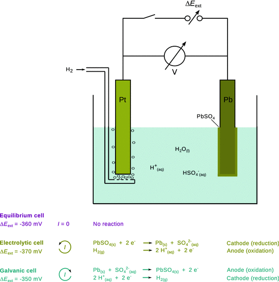
Fig. 4.8
Depending on the external potential difference, an electrochemical cell can either run as electrolytic cell, galvanic cell or rest at equilibrium
![]()
An external potential difference that is more negative than ΔE cell will operate the cell as an electrolytic cell with the reverse chemical reaction:
![]()