Process Technology: An Introduction - Haan A.B. 2015
4 Chemical reactors and their industrial applications
4.2 Stirred tank reactors
4.2.1 Description
Most stirred tanks used as chemical reactors are cylindrical and are equipped with a centrally positioned stirrer. The volume of the tank is normally determined by the residence time required, but the aspect ratio of the tank (height/diameter, H/D) can be selected. Bulk mixing is favored by H/D = 1, while a large H/D ratio is desired when heat must be transferred. Therefore a compromise is often necessary. Whenever possible, wall baffles are installed inside the vessel. These baffles prevent the rotation of the reactor contents with the stirrer. Wall baffles are avoided in systems prone to fouling or in systems in which gas or a floating material is to be entrained in the liquid.
A jacket is often fitted around the vessel to provide heat transfer. In addition a heating or cooling coil is often used to improve heat transfer. Stirrers are used to enhance the contacting, mixing, mass, and heat-transfer processes. A wide variety of stirrers is available. If the aspect ratio of the tank (H/D) is greater than 1.5, it is recommended to use additional stirrers on the shaft. Spacing of the stirrers should be approximately equal to the tank diameter. Selection of stirrers is initially based on the reaction mixture.
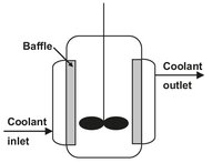
Fig. 4.1: Schematic of a jacketed batch reactor with baffles.
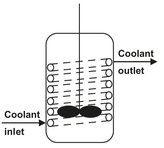
Fig. 4.2: Schematic of a batch tank with internal heating/cooling coil.
4.2.2 Batch stirred tank reactors
There is a tendency in chemical engineering to try to make all processes continuous. Whereas continuous reactors are likely to be most economic for large-scale production, batch reactors may be preferred for small-scale production of multiple low-volume high-priced products in the same equipment, particularly if many sequential operations are employed to obtain high product yields. A batch reactor is one in which the feed material is treated as a whole for a fixed period of time. A big advantage of batch reactors in the dyestuff, fine chemical, and pharmaceutical industries is their versatility. A corrosion-resistant batch reactor with heating and cooling coils can be used for a wide variety of similar kinds of reactions. The relatively small batch reactors used for these kinds of applications generally require less auxiliary equipment, such as pumps, and their control systems are less elaborate and costly than those for continuous reactors. In addition, additional process steps upstream or downstream of the reaction can also be performed in the reactor.
Batch reactors may also be justified when long reaction times are required to achieve a desired conversion, or when continuous flow is difficult, as it is with highly viscous or sticky solid-laden liquids. Because residence times can be more uniform in batch reactors, better yields and higher selectivity may be obtained than with continuous reactors. This advantage exists when undesired reaction products inhibit the reaction, or when the product is an unstable or reactive intermediate. In some processes, such as polymerization and fermentation, batch reactors are traditionally preferred, because the interval between batches provides an opportunity to clean the system thoroughly. Some important industrial applications of batch reactors are listed in Tab. 4.1.
Tab. 4.1: Some examples of the industrial application of batch reactors.
|
Long reaction times |
Biotechnological processes |
Polymer latices |
|
Polycondensation resins |
|
|
Multiple reaction steps |
Pharmaceutical ingredients |
Agrochemicals |
|
Polypropylene slurry polymerization |
|
ABS (acrylonitrile-butadiene-styrene) emulsion polymerization |
One of the main disadvantages of batch tank reactors is the relatively high operating cost due to long downtimes between batches and high manpower requirements. A second important disadvantage is the difference in quality between charges, because reaction conditions are only partly reproducible. When an external jacket is used, the temperature control capabilities are usually limited, especially with highly endothermic or exothermic reactions.
Fine chemical products such as pharmaceutical ingredients are usually produced in multipurpose batch reactors with volumes between 1 and 10 m3. Many of the reactors are glass lined because of the corrosive conditions which are employed. As illustrated by Fig. 4.1, heating and cooling are accomplished through an external jacket. After dosing the liquid reactants and solvents from barrels or storage tanks, the solid reactants are in most cases added manually from bags. The reactor content is then heated to start the reaction, which is allowed to proceed until the desired conversion is reached. In case of strongly exothermic or endothermic reactions, significant amounts of heat have to be supplied or removed. In those situations the heating or cooling capacity of the external jacket often limits the maximum production rate.
Batch reactors with internal heating/cooling coils (Fig. 4.2) are employed in production of saturated and unsaturated polyester resins from dicarboxylic acids and diols. An example is the reaction of neopentylglycol with terephthalic acid:
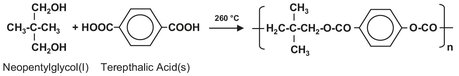
The polyesterification reaction is normally carried out in stainless steel vessels ranging from 8-20 m3. The reactor is filled with liquid glycols from a metering tank and then heated to about 110 °C. At this temperature the reaction can start, and the solid dicarboxylic acids are added from big bags. Blade agitators are used to homogenize the reaction mixture during polymerization. The water formed in the reaction is first used to build up pressure to increase the reaction temperature gradually to about 260 °C. Additional water is evaporated and separated out from the entrained glycol in a distillation column. Once the polymer is formed, the reaction mixture is cooled to below 180 °C before draining it on flake belts or into a cooled blend tank containing styrene monomer.
Batch reactors are also used for multiple phase reactions. A good example is the hydrogenation of benzaldehyde to benzylalcohol with the aid of an aqueous slurry of porous nickel catalyst particles:
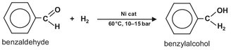
Vigorous stirring ensures that the catalyst is homogeneously dispersed in the liquid phase. The hydrogen gas is fed to the reactor below the stirrer through a sparger. The stirrer is designed in such a way that gas is sucked into the stirrer shaft and recirculated to the liquid. At the surface of the catalyst, particle reaction takes place between the dissolved hydrogen and an adsorbed benzaldehyde molecule. The produced benzylalcohol desorbes from the catalyst surface and dissolves in the liquid. When the benzaldehyde is fully converted, the hydrogen supply and the stirrer are stopped, so as to allow the catalyst to settle on the bottom of the reactor.
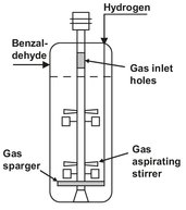
Fig. 4.3: Schematic drawing of batch reactor for benzaldehyde hydrogenation.
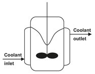
Fig. 4.4: Schematic of a polypropylene slurry polymerization reactor with a vortex.
Other applications of multiphase batch reactors involve the slurry polymerization of polypropylene, emulsion polymerization of polymer latices (polystyrene, polybutadiene, ABS), and suspension polymerization (SAN, PVC). Interestingly, the reactors in the polypropylene slurry process are deliberately operated with a large vortex to enhance transfer of the gaseous propylene into the slurry where the polymerization takes place (Fig. 4.4). The reactor is jacketed to remove the heat of polymerization.
4.2.3 Continuously-stirred tanks
The stirred tank reactor (Fig. 4.5), in the form of either a single tank or more often a series of tanks, is particularly suited for liquid-phase reactions, and is widely used in the organic chemicals industry for medium— and large-scale production. Other applications often encountered are gas-liquid reactions and gas-liquid reactions over suspended catalysts. This can form a unit in a continuous process, giving consistent product quality, ease of automatic control, and low manpower requirements. Although the volume of a stirred tank must be larger than that of a plug-flow tubular rector for the same production rate, it has only a small disadvantage, because large volume tanks are relatively cheap to construct. If the reactor has to be cleaned periodically, as happens sometimes in polymerization or in plants manufacturing a variety of products, the open structure of a tank is advantageous. When high conversions of reactants are needed, several stirred tanks in series can be used. Equally good results can be obtained by dividing a single vessel into compartments while minimizing back-mixing and short-circuiting (Fig. 4.6). The larger the number of stages, the closer performance approaches that of a tubular plug-flow reactor.
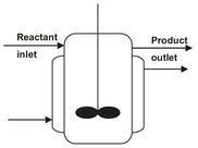
Fig. 4.5: Schematic of a continuously-stirred tank reactor.
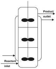
Fig. 4.6: Schematic of a continuously-stirred tank reactor with compartments.
In a continuous-flow stirred tank reactor (CSTR), reactants and products are continuously added and withdrawn. In practice, mechanical or hydraulic agitation is required to achieve uniform composition and temperature. The reactants are diluted immediately on entering the tank. In many cases, this favors the desired reaction and suppresses the formation of by-products. Because fresh reactants are rapidly mixed into a large volume, the temperature of the tank is readily controlled, and hot spots are much less likely to occur than in tubular reactors. Moreover, if a series of stirred tanks is used, it is relatively easy to keep each tank at a different temperature, so that an optimum temperature sequence can be attained.
Continuous-flow stirred tank reactors in series are simpler and easier to design for isothermal operation than tubular reactors. Reactions with narrow operating temperature ranges or those requiring close control of reactant concentrations for optimum selectivity benefit from series arrangement. If severe heat-transfer requirements are imposed, heating or cooling zones can be incorporated within or external to the CSTR. For example, impellers or centrally mounted draft tubes circulate liquid upward, then downward through vertical heat-exchanger tubes. In a similar fashion, reactor contents can be recycled through external heat exchangers. A different solution is used in the solution polymerization processes used for the production of polyethylene, EPDM rubber, and SMA polymers. As illustrated by Fig. 4.7, the monomers are dissolved in the solvent and cooled to a temperature of -30 °C. The continuously stirred tank reactor is operated adiabatically, during which the heat of polymerization is taken up by the reaction mixture and the temperature rises to 150-200 °C. The polymer is recovered from the solution by evaporating the solvent, which is recycled to the deep cooling.
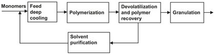
Fig. 4.7: Block scheme of a solution polymerization plant.
Continuously-stirred tank reactors with several compartments in series are employed in many different processes, such as the production of docan in the α-picoline process, synthesis of urea, high pressure polyethylene autoclave reactor, mass polymerization of styrene, and suspension polymerization of ABS and SAN. Depending on the specific application, vertical reaction columns or horizontal reactors are used. Each compartment can contain a stirrer and cooling coil. In mass polymerization processes, each reactor compartment is equipped with a condensor to remove the heat of polymerization by evaporating solvent or monomer. This is schematically illustrated in Fig. 4.8.
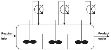
Fig. 4.8: Drawing of a stirred three-compartment tank reactor with condensors for heat removal.
4.2.4 Cascade of stirred tanks
A cascade of stirred tank reactors is employed in many different processes such as polymerizations and oxidations. One example is the uncatalyzed oxidation of cyclohexane to cyclohexylhydroperoxide:
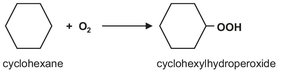
As illustrated in Fig. 4.9, a cascade of stirred tanks is used for the oxidation to minimize back mixing of the produced cyclohexylhydroperoxide and allow better control of the air distribution over the liquid. All reactors contain an air sparger and are stirred to facilitate dissolution of oxygen. To keep the selectivity around 80 %, the overall conversion is limited to 5-10 %. The heat of reaction is removed by the cyclohexane evaporated by unconverted air. After oxidation, the cyclohexylhydroperoxide is decomposed to yield the desired products cyclohexanone and cyclohexanol:
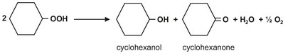
Besides the main products, significant amounts of side-products such as acids, esters, and acetals are formed.
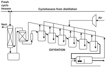
Fig. 4.9: Cyclohexane oxidation reactor section.