Process Technology: An Introduction - Haan A.B. 2015
4 Chemical reactors and their industrial applications
4.5 Bubble columns
Bubble columns are devices in which gas bubbles are brought into contac with liquid. The most common purpose is to dissolve gaseous reactants in a liquid, often a catalyst containing reaction mixture, to form the desired products. Oxidation, hydrogenation, chlorination, phosgenation, alkylation, and other processes have long been performed in bubble-column reactors in the chemical industry. Industrial reactors for high-tonnage products have volumes of 100-300 m3. Larger bubble columns, with volumes up to 3000 m3, are employed as fermentors. The largest units (20 000 m3) are found in waste water treatment.
The simplest design is the bubble column, where the gas is fed into the column at the bottom and rises through the liquid, escaping from it at the upper surface. Depending on the intensity of mixing and the rate of chemical reaction, the gas is consumed to a greater or lesser extent. When the off-gas contains high concentrations of valuable reactants, part of it is recycled to the reactor. This recycling design, however, lowers the concentration profile in the bubble column and must be optimized from an economic standpoint. In a simple bubble column the liquid is led either cocurrently or countercurrently to the upward gas stream and has a long residence time. The flow direction of the liquid phase has minimal effect on the gas-phase residence time, which is comparatively short.
Usually the gas is dispersed to create small bubbles and distribute them uniformly over the cross section of the equipment to maximize the intensity of mass transfer. In most cases pores or holes are used to generate gas bubbles. Fig. 4.18 shows typical forms of a static gas sparger, in which bubble formation occurs without any additional energy supplied from outside. The simplest of these devices, the dip tube, only gives an acceptably uniform gas distribution over the cross section at some distance above the sparger. Perforated plates and perforated ring spargers are more effective. Both of them require a certain minimum gas flow rate to achieve uniform distribution and prevent the liquid from getting into the sparger. Very fine bubbles can be generated by the use of porous plates.
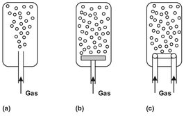
Fig. 4.18: Static gas spargers: (a) dip tube; (b) perforated or porous plate; (c) perforated ring.
A large scale industrial application of a bubble column for oxidation reactions is the conversion of toluene to benzoic acid:
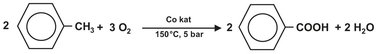
In this oxidation reaction an organic cobalt component is used as catalyst. The reaction is performed under pressure (± 5 bar) and at a temperature of about 150 °C. A perforated ring sparger is used to introduce the air in the reactor. (Fig. 4.19) The cobalt catalyst enhances the rate of reaction to such an extent that the oxygen reacts almost momentarily after dissolving in the liquid toluene, and the off-gas contains only 1-2% residual oxygen. Evaporation of toluene is used to remove the heat of reaction and thereby control the reaction temperature. After condensing, the evaporated toluene is recycled to the reactor. Due to the high gas velocity in the reactor the contents is very well mixed by the bubbles and can be described as an ideal stirred tank reactor.
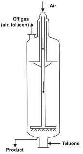
Fig. 4.19: Schematic of the toluene oxidation reactor.
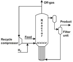
Fig. 4.20: Bubble column hydrogenation reactor for hydroxylamine production.
A bubble column with a heterogeneous catalyst is used in the preparation of hydroxylamine for the caprolactam production (Fig. 4.20). Hydrogen is used to reduce ammonium nitrate in an acidic environment over a Pd/C catalyst. Besides the desired main reaction, several parallel reactions are responsible for the formation of N2 and N2O:
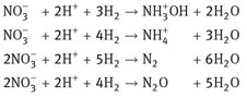
A large gas recycle is used to disperse the catalyst particles in the reactor. This way the reactor contents are well mixed, and a gas-liquid-solid or slurry reactor is obtained. The catalyst particles containing liquid are circulated over an external loop, where candle filters are used to separate the catalyst particles from the product stream. These filters consist of porous metal tubes that are only permeable for the liquid. Almost no catalyst losses are observed. The heat of reaction is removed in the heat exchanger in the bottom of the reactor. A continuous liquid circulation is maintained through the communicating vessel principle, because the high gas holdup reduces the volumetric density in the left leg considerably compared to the right leg.