Process Technology: An Introduction - Haan A.B. 2015
11 Particle removal from gases
11.5 Electrostatic precipitation
11.5.1 Principles
In electrostatic precipitation electrostatic forces are used to remove the solid or liquid particles suspended in a gas stream. An efficient separation is achieved by creating an electrostatic charge on the particles through the generation of ions in the gas, which unload their charge on the particles by collision or diffusion. In electrostatic precipitators, ions are created in the gas by exposure to corona discharge in high-density electrostatic fields. This is accomplished by applying high voltages (30-100 kV) to an assembly of negatively-charged wires and positively-grounded collection plates. At the wires the corona discharge occurs when positive ions in the gas impinge on the negatively-charged wires and release electrons that ionize the gas into positive ions and electrons. While the positive ions produce further ionization, the electrons which were produced associate with gas molecules to form negative ions traveling across the gas flow to the positively charged collecting electrodes. This continuous flow of negative ions effectively fills the space between the electrodes with negative ions that charge the particles passing through the space with the gas by two mechanisms: bombardment charging and diffusion charging. Bombardment charging occurs by ions that move towards the positive electrode with high velocity and impact on the particles. In diffusion charging the thermal movement of the ions in the gas leads to particle-ion collisions. The charging continuous until the so-called equilibrium charge on the particle repels further ions.
As soon as the dust particles acquire some negative charge they will migrate towards the positive collector electrodes away from the negative discharge electrode. Although the overall picture is very complex, the calculation of the particle drift velocity is usually based on a relatively simple model with the following assumptions:
· (1) the particle is considered fully charged during the whole of its residence in the precipitating field;
· (2) uniform distribution of particles through the precipitator cross section;
· (3) particles moving towards the electrode normal to the gas stream encounter fluid resistance in the viscous flow regime and Stokes law can be applied;
· (4) repulsion effects between the particles are neglected;
· (5) there are no hindered settling effects in the concentrated dust near the wall;
· (6) the effect of the movement of the gas ions, sometimes called the electric wind, is neglected;
· (7) the gas velocity through the precipitator does not affect the migration velocity of the ions;
· (8) the particles move at their terminal velocity.
Although it can hardly be realistic, the migration velocity based on these eight assumptions has been found to give reasonable estimates of the cross-stream drift velocity. For a particle with saturation charge q moving in a field of constant intensity E, the terminal migration velocity vt towards the collecting electrode may be determined from an equilibrium between the electrostatic force and the drag force:
![]()
(11.10)
Rewriting gives for the migration velocity of particle
![]()
(11.11)
On arrival at the earthed collector, the particles adhere and are discharged to earth potential. The strong electrostatic field and adhesive properties of the particulate inhibit reentrainment. When a layer of particles has formed, these are shaken off by rapping and fall into a hopper.
11.5.2 Equipment and collecting efficiency
Electrostatic precipitators can be classed as single— or two-stage. In the two-stage designs, used for air purification, air conditioning, or ventilation, particle charging and collection are carried out in two separate stages. As illustrated by Fig. 11.10, the dust particles are first charged in a separate charging section, providing only a fraction of a second residence time to avoid collection. Particle collection follows in the second stage, which consists of alternately charged parallel plates. As laminar flow conditions usually prevail in two-stage precipitators, the particle-collecting efficiency ηF can be expressed in direct analogy with sedimentation tanks:
![]()
(11.12)
where vt is the effective migration velocity of the dust particles, A is the collecting area, and Q is the gas flowrate. Eq. (11.12) can be rewritten in terms of the gas velocity vg, the electrode spacing W and the length of the collector electrodes L:
![]()
(11.13)
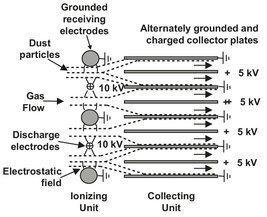
Fig. 11.10: Schematic of a two-stage electrostatic precipitating unit.
Application of this equation is limited to the two-stage precipitator, which is the only type built for laminar flow. In most industrial applications single-stage units designed for operation in the turbulent flow regime causing turbulent diffusion and reentrainment are used. It was found experimentally that the efficiency of a precipitator was an exponential function of the gas-stream residence time in the precipitator field. Under the conditions that the dust is uniformly distributed in the beginning, the uncollected dust remains uniformly distributed, and the migration velocity is effectively constant, Deutsch derived the following equation for the collecting efficiency:
![]()
(11.14)
In single-stage units the particles are charged and collected in the same electrical field, thus making the design simpler. For a round wire axially suspended in a tube, a radial, evenly distributed electrostatic field is obtained. To accommodate larger gas flows, banks of tubes are nested together vertically to facilitate the removal of the deposited dust by gravity (Fig. 11.11). Wire-in-tube separators are employed for small quantities of gas. The wire-in-tube precipitator was the earliest type used, but it has now been almost entirely replaced by the plate type. Wire-and-plate or simply plate precipitators consist of vertical parallel plates with vertical wires arranged at intervals of 0.1 to 0.2 m along the centerline between the plates (Fig. 11.12). The wires have a negative charge, while the plates are normally earthed. A plate precipitator may have 10-15 m-tall parallel flat plates with 0.2-0.4 m horizontal spacing and discharge electrodes which are suspended midway between the plates.
Both the discharge and collecting electrodes must be rapped at preset time intervals because clean electrodes are essential for the generation of an effective corona discharge and electrostatic field. Particles are removed by vibrating the collection plates, thereby dislodging the particles, which drop into collection hoppers. Swing hammers or camshaft and coil springs are most commonly used for mechanical rapping. Electromagnetic or pneumatic devices allow easier adjustment of the timing and intensity of the rapping than the mechanical devices. In the wet two-stage tubular precipitator the deposited dust is removed from the collection electrodes by a flowing water film. This device consists of a short ionizing section followed by a relatively long collection system. The discharge electrode is in the form of a rod or a tube with a section of sharp discharge points at the end, centered in the collection tube.
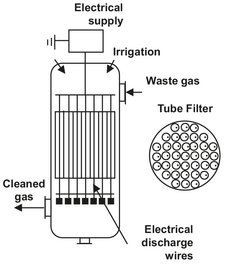
Fig. 11.11: Diagram of a tube-type single-stage electrostatic precipitator.
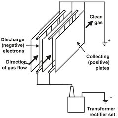
Fig. 11.12: Schematic of a single-stage electrostatic plate separator.
Electrostatic precipitators are applied wherever very large volumes of gases have to be cleaned with high collection efficiency on fine particles and there is no explosion risk. The plants are invariably used for fly ash collection in large (800-1200 MW) coalfired electric power stations and for the collection of dusts in the cement industry. Precipitators are also employed for large-scale fume collection systems in the metallurgical industry.