Process Technology: An Introduction - Haan A.B. 2015
11 Particle removal from gases
11.8 Wet scrubbers
The effectiveness of rain in removing airborne dust from the atmosphere has been used in industry to develop a variety of liquid scrubbing equipment. In scrubbers, the gas to be purified must pass through a dense cloud of drops formed by the scrubbing liquid. The gas must flow past the scrubbing drops that act as targets for the particles. Scrubbers operate by collecting dust particles on the scrubbing liquor droplets and binding them to it. Wettability of the particles does not play a crucial role in binding. Decisive in separation are the collecting mechanisms that are the same as in impingement separators and filters: inertial impaction, interception, and diffusion. Although inertial interception predominates in most scrubbers, diffusion becomes important for particle sizes in the submicron range. Wet scrubbers are able to collect particles and droplets up to very small diameter (< 0.1 µm).
Development and sizing of scrubbers are often purely empirical, because the processes that occur in these complicated pieces of equipment are complex and difficult to simulate with theoretical models. However, some models have been developed that are quite helpful, because they allow identification of important parameters. In these models the scrubbing liquor is assumed to be in droplet form, and inertial forces are considered the dominant collecting mechanism of dust particles on the droplet. Like in fiber filters, the collecting efficiency of a wet scrubber is the result of the collective cleaning capacities of all the droplets present. The separation zone can be thought of as a dense curtain of washing droplets which must be crossed by the gas flow. Then, in principle, one can apply the theory for filters to estimate the collecting efficiency of scrubbers:
![]()
(11.20)
where ηF(0) denotes the collection efficiency of a single droplet and p’ the total relative on-flow area of all n washing droplets in the scrubber with cross sectional area A. Hence p’ is
![]()
(11.21)
The collection efficiency of a scrubber thus increases with water loading and the diameter of the sprayed droplets. However, the single drop collecting efficiency is also a strong function of the diameter of the particles to be captured. The optimum spray droplet size for maximum collecting efficiency can be obtained from Fig. 11.20.
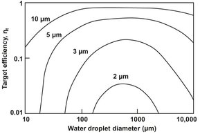
Fig. 11.20: Collecting efficiency of a wet scrubber.
Scrubbers are relatively easy to adapt to various operating conditions. They are employed mainly when products are to be recovered from a wet phase or when the risk of dust explosion rules out dry collection. The spray tower is the simplest and oldest type of scrubber. Liquid droplets are produced by spray nozzles mounted at different levels and allowed to fall downwards through a rising stream of dirty gas. In order not be entrained by the gas, the droplets must be sufficiently large to have a falling speed greater than the upward velocity of the gas stream. Because the droplets used are in the order of 0.1-1 mm diameter, the particles collected are comparatively large, and the predominant collection mechanisms are inertial impaction and interception. The dust-laden liquid leaves the bottom of the scrubber. A typical spray tower is shown in Fig. 11.21. Packings are sometimes used to improve collection efficiency. If the dirty gas stream encounters a series of liquid films or impinges on a succession of pools, the better collection efficiency is achieved than for the simple scrubbers. These ideas have been incorporated in packed-bed scrubbers that contain packings such as Raschig rings or saddles. The efficiency of particle collection can be further improved by increasing the relative velocity of the droplets and the gas stream. This is achieved by using the centrifugal force of a spinning gas stream rather than the gravitational force in the simple tower. In rotational scrubbers the washing fluid is dispersed radially in the gas by rotating spray nozzles. The gas spirals upward, and the dirty water is removed from the bottom of the scrubber. In commercial designs the spinning motion is imparted to the gas stream by tangential entry with velocities between 15 and 60 m/s. The liquid is directed outwards from sprays set in a central pipe.
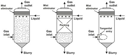
Fig. 11.21: Drawing of a spray, packed, and rotational scrubber.
In many scrubber designs the gas stream breaking through a sheet of liquid or impinging on a pool forms the scrubbing droplets. An example such a self-induced spray scrubber is shown in Fig. 11.22, where the gas stream breaks through a pool of liquid and then creates a liquid curtain because of the specially designed orifices. These plants are extensively used in the metallurgical industry for dusts and sticky materials. Entrained dust-laden fluid collects inside the scrubber in the collection tank. The resulting slurry must be removed regularly.
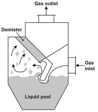
Fig. 11.22: Self-induced spray scrubber.
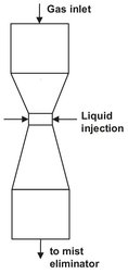
Fig.11.23: Venturi scrubber.
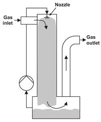
Fig. 11.24: Ejector venturi scrubber.
Venturi scrubbers (Fig. 11.23) have the highest collection efficiency. The gas is accelerated up to 100 m/s in the venturi throat (orifice). Washing fluid enters the middle of the throat just in front of its narrowest point or is fed radially into the throat. The liquid is atomized into very small droplets by the high speed of the inflowing gas. Aerosol particles are collected and captured by the accelerating liquid droplets. A cyclone or wire demister is needed to separate the dust-laden water droplets from the gas.
The ejector venturi scrubber (Fig. 11.24) is basically a water-jet pump. Water is sprayed into the scrubber and provides a draft for moving the gas. The velocity of the gas causes disintegration of the liquid. Two successive stages are often used to reach the desired collection efficiency.
Nomenclature
A |
area |
[m2] |
d, D |
diameter |
[m] |
Db |
characteristic baffle dimension |
[m] |
E |
electric field strength |
[V m-1 = N C-1 = m kg s-3 A-1] |
g |
gravitational acceleration |
[m s-2] |
G(dp) |
collection efficiency |
[-] |
h, H |
height |
[m] |
L |
length |
[m] |
n |
number of layers/droplets |
[-] |
NS |
separation number |
[-] |
p |
relative on-flow area |
[m2] |
Re |
Reynolds number |
[-] |
Sc |
sharpness of cut |
[-] |
t |
time |
[s] |
q |
charge |
[C = A · s] |
Q |
volume flow rate |
[m3 s-1] |
v |
velocity |
[m s-1] |
V |
volume |
[m3] |
W |
chamber width |
[m] |
W |
electrode spacing |
[m] |
η |
viscosity |
[kg s-1 m-1 = N · s m-2 = Pa·s] |
ηM |
efficiency of particle collection |
[-] |
ηF |
collection efficiency |
[-] |
ηF(n) |
collection efficiency of n wires |
[-] |
p, ps |
density, solid density |
[kg m-3] |