Process Technology: An Introduction - Haan A.B. 2015
12 Membrane separations
12.3 Membrane filtration processes
Various pressure-driven membrane filtration processes can be used to concentrate or purify a dilute solution. In these processes the solvent is the continuous phase, and the concentration of the solute is relatively low. The necessary structure of the membranes employed is determined by the particle or molecular size. Particles with a diameter > 0.1 µm are already retained by a rather open membrane structure in a process called microfiltration. The separation of macromolecules from an aqueous solution requires a more dense membrane structure, and the process is called ultrafiltration. In reverse osmosis and nanofiltration, low molecular weight components of approximately equal size are separated from each other. In this case a very dense (asymmetric) membrane is used. Going from microfiltration through ultrafiltration to reverse osmosis and nanofiltration, the hydrodynamic resistance of the membrane increases, and consequently a higher pressure difference is needed. Typical values for applied pressures and fluxes have already been given in Tab. 12.1.
12.3.1 Microfiltration
Microfiltration is used in a wide variety of industrial applications where particles of a size > 0.1 µm, such as colloids, dyes, and microorganisms, have to be retained from a liquid or a gas. One of the main industrial applications is the sterilization and clarification of all kinds of beverages and pharmaceuticals. In fact, microfiltration was developed to separate microorganisms from water and is the oldest and and most widely used application of membrane separation. New fields of application are biotechnology and biomedical technology. In biotechnology, microfiltration is especially suitable in cell harvesting.
The most important applications today are still based on dead-end filtration. In this process design the entire fluid flow is forced through the membrane, which usually operates as a depth filter and collects the particles within the membrane. As particles accumulate in the membrane interior or on its surface, the pressure required to maintain the required flow increases. In cross-flow microfiltration systems screen filter membranes that collect retained particles on the surface are increasingly preferred. Cross-flow systems are more complex than dead-end filter systems, because they require additional auxiliary equipment such as a recirculation pump, valves, etc. However, a screen membrane has a much longer lifetime than a depth membrane, and it can be regenerated by back flushing. Cross-flow filtration is increasingly being adopted for microfiltration of high volume industrial streams containing significant particle levels.
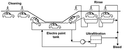
Fig. 12.14: Flow scheme of an electro coat paint ultrafiltration system.
12.3.2 Ultrafiltration
Ultrafiltration is used over a wide range of applications involving situations where high molecular weight components have to be separated from low molecular weight components. The particle size rejected from the permeate stream ranges from 0.1 µm to 1 nm. Early and still important applications were the recovery of electro coat paint from industrial coating operations, as shown in Fig. 12.14, and the clarification of emulsified oily wastewaters in the metalworking industry. More recent applications are in the food and dairy industries for the concentration of milk, recovery of whey proteins, and clarification of fruit juices and alcoholic beverages. With the ultrafiltration process illustrated in Fig. 12.15, whey is separated into an aqueous solution of lactose and salts (permeate), retaining casein, butterfat, bacteria, and proteins in the retentate. Other examples are the latex particle recovery from wastewater, separation of macromolecular solutions, and the manufacturing of sterile vaccines by removing viruses from solution. In reverse osmosis and nanofiltration processes ultrafiltration as well as microfiltration are frequently employed as a pretreatment step.
An important difference from microfiltration is that ultrafiltration membranes have an asymmetric structure with a much denser top layer and consequently a much higher hydrodynamic resistance. The top layer thickness is generally less than 1 µm. The membranes are characterized by their molecular weight cut-off, defined as the molecular weight of the globular protein molecule. of which 95 % is rejected by the membrane. The rejection of linear polymer molecules of equivalent molecular weight is usually much less, because they are able to sneak through the membrane pores, whereas more rigid globular molecules are retained. An important point which must be taken into account is that the process performance is not equal to the intrinsic membrane properties in actual separations due to concentration polarization and fouling.
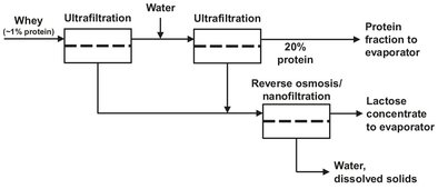
Fig. 12.15: Simplified flow scheme of an ultrafiltration/reverse osmosis process to extract valuable components from cheese whey.
12.3.3 Reverse osmosis and nanofittration
Nanofiltration and reverse osmosis are used when low molecular weight solutes such as inorganic salts or small organic molecules such as glucose or sucrose have to be separated from a solvent. The difference to ultrafiltration lies in the size of the solute. Consequently, denser membranes are required with a much higher hydrodynamic resistance. A much higher pressure must be applied to force the same amount of solvent through the membrane. Moreover, the osmotic pressure which arises when two solutions of different concentration are separated by a semipermeable membrane has to be overcome. This situation is illustrated schematically in Fig. 12.16. Because the solvent molecules in the dilute phase have a higher chemical potential than those in the concentrated phase, the solvent molecules flow from the dilute phase to the concentrated phase. This process continues until osmotic equilibrium has been reached. The resulting hydrodynamic pressure difference Δ P is called the osmotic pressure difference ΔΠ. In reverse osmosis this process is reversed by applying an external hydrostatic pressure to force water into the direction of the clean water product. A complication may be the increasing salt concentration in the remainder of the solution, causing the osmotic pressure to increase to such an extent that the required value of hydrostatic pressure becomes too high for practical purposes. If it is assumed that no solute permeates through the membrane, the effective water flow can be described by
![]()
(12.11)
where A is a proportionality constant, ΔP is the applied pressure difference, and ΔΠ is the osmotic pressure differential across the membrane. As this equation shows, water flows from the dilute to the concentrated salt-solution side by normal osmosis at low applied pressure ΔP < ΔΠ. When the applied pressure is higher than the osmotic pressure, water flows from the concentrated to the dilute salt-solution side of the membrane.
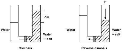
Fig. 12.16: Principle of osmosis and reverse osmosis.
The production of potable water was the first membrane-based separation process to be commercialized on a significant scale. The discovery of the asymmetric cellulose acetate membrane made desalination by reverse osmosis technically and economically feasible. The first cellulose di-acetate modules had a salt rejection of 97-98 %. This was enough to produce potable water (< 500 ppm salt) from brackish water (Fig. 12.17), but insufficient for the desalination of seawater. Seawater desalination came within reach by the development of interfacial composite membranes with salt rejections greater than 99.5 %. The general trend of the desalination industry is toward spiral-wound modules. Besides the application of reverse osmosis in drinking water, a second important market is the production of ultrapure water. Such water is used in steam boilers or in the electronics industry, where extremely pure water with a total salt concentration below 1 ppm are required to wash silicon wafers. Other applications where reverse osmosis may be used are the food industry (fruit juice, sugar, coffee), the galvanic industry (waste streams), and the dairy industry (milk).
While reverse osmosis and nanofiltration are closely related in terms of applications, their separation mechanisms are quite different. Whereas reverse osmosis is based on reversing the phenomena of osmosis, nanofiltration can be considered a filtration process though nanometer pores. The network structure of nanofiltration membranes is more open, implying that the retention for monovalent ions becomes much lower, but the retention for bivalent ions remains very high. In addition the retention is high for microsolutes such as herbicides, insecticides, pesticides, dyes, and sugars. Since the water permeability of nanofiltration membranes is much higher, it is to be preferred over reverse osmosis for somewhat larger microsolutes and when a high retention for monovalent salt is not required.
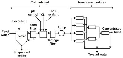
Fig. 12.17: Typical brackish water reverse osmosis desalination plant.
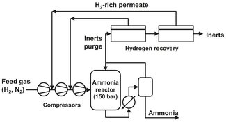
Fig. 12.18: Flow scheme of a membrane system to recover hydrogen from an ammonia reactor purge stream.