Process Technology: An Introduction - Haan A.B. 2015
12 Membrane separations
12.2 Principles
12.2.1 Membranes
In essence a membrane is a discrete thin interface that should be semipermeable to at least one component of the mixture to be separated. A wide variety of synthetic membranes exist that differ in chemical composition, physical structure, and the way they operate. They are commonly classified by their morphology, because the membrane structure determines the separation mechanism and hence the type of application. The principal types of membranes are shown schematically in Fig. 12.4.
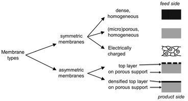
Fig. 12.4: Principal types of solid membrane structures.
A homogeneous microporous membrane is very similar in its structure and function to a conventional filter. It has a rigid, highly porous structure with randomly distributed interconnected pores. However, compared to a conventional filter these pores are extremely small (0.01-10 µm). All particles larger than the largest pores are completely rejected by the membrane by size exclusion. Partial rejection occurs for particles smaller than the largest pores, but larger than the smallest pores. Thus separation of solutes by microporous microfiltration and ultrafiltration membranes depends mainly on size of the solute/particle and pore size distribution of the membrane. In general effective separations are only possible for molecules that differ considerably in size. Homogeneous dense membranes consist of a dense film through which permeants are transported by diffusion under the driving force of a pressure, concentration or electrical potential gradient. The separation of various components of a solution is related directly to their relative transport rate within the membrane, which is determined by their diffusivity and solubility in the membrane material. Most gas separation, pervaporation, and reverse osmosis membranes use dense membranes to perform the separation. However, the thickness (10 to 200 µm) required for mechanical stability makes transport through homogeneous dense membranes uneconomically low. Because the transport rate is inversely proportional to the membrane thickness, high transport rates can be achieved by making the membrane as thin as possible. A breakthrough for many industrial applications was the development of asymmetric membrane structures. Asymmetric membranes consist of a very dense top layer with a thickness of 0.1-0.5 µm on a porous sublayer with a thickness of about 50-150 µm that acts as the mechanical support. These membranes combine the high selectivity of a dense membrane with the high permeation rate of a very thin membrane. The separation properties and permeation rates are determined largely or completely by the thin top layer. The advantage of higher fluxes is so great that almost all commercial dense membranes have an asymmetric structure. Electrically charged membranes are most commonly microporous with positively or negatively charged ions fixed to the pore walls. They are used for processing electrolyte solutions in electrodialysis. A membrane with positively charged ions is referred to as an anion-exchange membrane because it binds anions in the surrounding fluid. Similarly, a membrane containing negatively charged ions is called a cation-exchange membrane. Separation with charged membranes is achieved mainly by exclusion of ions with a charge like that of the ion-exchange membrane and is affected by the charge and concentration of the ions in solution. Monovalent ions are excluded less efficiently than divalent ions, and selectivity decreases in solutions of high ionic strength.
Membrane materials can be polymeric, inorganic, or even metallic. In principle all polymers can be used for the preparation of organic (polymeric) membranes, but the chemical and physical properties differ so much that only a limited number are used in practice. Often a distinction is made between open porous and dense nonporous membranes. For the porous microfiltration/ultrafiltration membranes the choice of material is mainly determined by the processing requirements, fouling tendency, and the chemical/thermal stability of the membrane. Hydrophobic materials such as polytertrafluorethylene (PTFE), polyvinylidenefluoride (PVDF), and isotactic polypropylene (PP) are often used for microfiltration membranes. The best-known hydrophilic polymers are cellulose and its ester derivatives, such as cellulose acetate and cellulose triacetate. Besides in microfiltration and ultrafiltration, they are also used in reverse osmosis, gas separation, and pervaporation. Other important hydrophilic polymers are aromatic and aliphatic polyamides, which both show outstanding performance and membrane stability. Because ultrafiltration membranes require a different preparation method than microfiltration membranes, polysulfones (PS) and polyethersulfones (PES) are often a very important class for ultrafiltration membranes. Other polymers of importance for the manufacturing of ultrafiltration membranes are polyimides and polyacrylonitrile. In nonporous composite or asymmetric membranes the porous support layer is often made of the above-mentioned polymers. The choice of material for the permselective skin is determined by the required performance and type of application. The applied types of polymer range from elastomers to glassy materials. Inorganic materials generally possess superior chemical and thermal stability relative to polymeric materials. Types that can be distinguished are ceramic, glass, and zeolite membranes. Ceramic, glass, and metallic membranes are usually prepared by sintering or by sol-gel processes. Zeolites are crystals with a defined, very narrow pore size that can be sintered into a membrane.
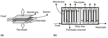
Fig. 12.5: Schematic drawing of (a) construction and (b) flow-path in a plate-and-frame module.
12.2.2 Modules
Industrial membrane plants often require hundreds to thousands of square meters of membrane area to perform the separation required on a useful scale. In these plants a bare membrane cannot be applied without the proper connections to direct a feed stream onto the membrane surface and to collect the permeate and the raffinate. The smallest unit into which the membrane area is packed and provides the necessary connections is called a membrane module. A number of module designs, based on flat or tubular membranes, are possible. Plate-and-frame and spiral-wound modules involve flat membranes, whereas tubular, capillary, and hollow fiber modules are based on tubular membranes.
Plate-and-frame modules were one of the earliest types of membrane systems. A schematic drawing is given in Fig. 12.5. Membrane, feed spacers and product spacers are layered together between two end plates. The feed mixture is forced across the surface of the membrane. A portion passes through the membrane, enters the permeate channel, and makes its way to a central permeate collection manifold. The packing density of such modules is about 100 to 400 m2/m3. The spiral-wound module can be considered as a plate-and-frame system wrapped around a central collection pipe. The packing density of this module (300-1000 m2/m3) is greater than of the plate-and-frame module. Membrane and permeate side spacer material are glued along three edges to build a membrane envelope. As shown in Fig. 12.6, this membrane envelope is wound around a perforated central collection tube and placed inside a tubular pressure vessel. Feed passes axially down the module across the membrane envelope where the feed-side spacer also acts as a turbulence promoter. Part of the feed permeates into the membrane envelope, where it spirals toward the center and exits through the collection tube.
Tubular modules are now generally limited to ultrafiltration applications, because their packing density of less than 300 m2/m3 is rather low. In general, tubular membranes are not self-supporting. They consist of a porous tubular stainless steel, ceramic, or plastic support, with the membrane placed on the inside of the tubes. As illustrated schematically in Fig. 12.7, multiple tubes (4-18) with diameters larger than 10 mm are put together in a module. The feed solution always flows through the center of the tubes, while the permeate flows through the porous supporting tube into the module housing. Capillary and hollow fiber modules consist of a large number of self-supporting membrane capillaries assembled together in a module, as shown schematically in Fig. 12.7. The free ends of the fibers are potted with agents such as epoxy resins, polyurethanes, or silicone rubber. In the bore-side feed type, the fibers are open at both ends, and the feed fluid is circulated through the bore of the fibers, with the permeate collected on the outside of the capillaries in the module housing. A packing density of about 600-1200 m2/m3 is obtained with modules containing capillaries. The difference between the capillary module and the hollow fiber module is simply a matter of membrane fiber dimensions. The hollow fiber module is the configuration with the highest packing density, which can attain values up to 30 000 m2/m3. The second type of capillary module is the shell-side feed type. In this module a closed bundle of fibers is contained in a pressure vessel. The system is pressurized from the shell side, and the permeate passes through the fiber wall and exits through the open fiber ends.
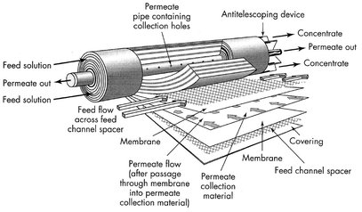
Fig. 12.6: Spiral-wound module. Reproduced with permission from [7].
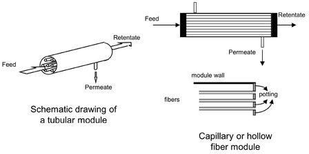
Fig. 12.7: Diagram of a tubular and bore-side-feed capillary or hollow fiber module.
12.2.3 Flux, permeability and selectivity
The performance or efficiency of a given membrane is determined by two parameters: its selectivity and its flow through the membrane. The latter, often denoted as the flux or permeation rate, is defined as the volume flowing through the membrane per unit area and time. In porous membranes the most common transport mechanism is the pressure-driven convective flow of the solvent and the flow of certain solutes through the pores. Separation occurs because certain larger solutes are excluded from some or all of the pores in the membrane through which the other permeants move. The convective flux through the membrane can be written as
![]()
(12.2)
which in the case of pressure-driven processes such as microfiltration, ultrafiltration, nanofiltration, and reverse osmosis becomes
![]()
(12.3)
where the membrane resistance Rtot is related to the membrane thickness δm, by the permeability Pm that contains structural factors such as the porosity and pore size as well as the viscosity of the permeating liquid.
For porous membranes the concentration profile is continuous from the bulk feed liquid to the bulk permeate liquid, because liquid is continuously present from one side to the other (Fig. 12.8a). This is not the case for the dense membrane in Fig. 12.8b, where permeants dissolve in the membrane material and then diffuse through the membrane down a concentration gradient. As a result the liquid phase concentration gradient Δ C should be multiplied by the thermodynamic equilibrium distribution coefficient Ki to obtain the true solute concentration gradient over the membrane:
![]()
(12.4)
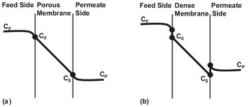
Fig. 12.8: Concentration profiles for solute transport through porous (a) and dense (b) membranes.
For gases the solubility can be related to the partial pressure by Henry’s law, giving
![]()
(12.5)
In both equations, De is the effective diffusion coefficient of the permeant through the membrane. They illustrate that for transport of a gas, vapor or liquid through a dense nonporous membrane the permeability is always described in terms of
![]()
(12.6)
where the solubility provides a thermodynamic measure of the amount of permeant sorbed by the membrane under equilibrium conditions, and the diffusivity depends on the geometry of the permant. Separation is obtained because of the differences in solubilities of the permeants in the membrane and the differences in the rates at which the permeants diffuse through the membrane. In general, convective pressure-driven membrane fluxes are high compared with those obtained by simple diffusion.
The selectivity of a membrane towards a mixture is generally expressed by the retention (R) or the separation factor (SF). For dilute aqueous mixtures it is more convenient to express the selectivity in terms of the retention towards the solute. The solute is partly or completely retained while the solvent (water) molecules pass freely through the membrane. The retention is given by
![]()
(12.7)
where CF is the solute concentration in the feed and CP is the solute concentration in the permeate. The value of R varies between 100 % for complete retention of the solute and 0 % when solute and solvent pass freely through the membrane. Membrane selectivity towards gas and liquid mixtures is usually expressed in terms of the separation factor. For a mixture consisting of two components the separation factor is given by
![]()
(12.8)
where y is the concentration of each component in the permeate and x the concentration of each component in the feed. The separation factor is usually calculated in such a way that its value is greater than unity. For the separation of a binary gas or liquid mixture in the absence of boundary layer or film mass-transfer resistances, the separation factor equation can be combined with the transport flux equations given in eqs. (12.4) and (12.5) and rearranged to give the ideal separation factor
![]()
(12.9)
Thus a high separation factor can be achieved from a high solubility ratio, a high diffusivity ratio, or both.
12.2.4 Concentration polarization and fouling
In membrane separation processes a separation is achieved because certain components are transported more readily than others. Because the feed mixture components permeate at different rates, concentration gradients form in the fluids on both sides of the membrane. This phenomenon, illustrated in Fig. 12.9, is called concentration polarization. In membrane filtration processes, such as reverse osmosis, nanofiltration, ultrafiltration, and microfiltration, certain solutes are retained by the membrane. As a result the concentration of retained solutes in the permeate is lower than the concentration in the bulk. The retained molecules accumulate at the membrane surface, where their concentration will gradually increase. Such a concentration build-up will generate a diffusive flow back to the bulk of the feed. At steady state the convective transport of solute to the membrane surface is balanced by the sum of its flux through the membrane plus the diffusive back transport of retained solute from the membrane surface to the bulk. In mathematical terms this balance can be expressed as
![]()
(12.10)
where D is the diffusion coefficient of the molecule in the boundary layer. The main effect of concentration polarization is a reduced flux at a finite time because of the counteracting retained solute concentration gradient. Especially in microfiltration and ultrafiltration the process flux may often be less than 5 % of the pure water flux. The problem is less severe in gas separation and pervaporation. Other consequences of concentration polarization can be a lower retention because of the increased solute concentration at the membrane surface or a higher retention when higher molecular weight solutes form a kind of second membrane. In principle concentration polarization is a reversible process, meaning that, when steady state conditions have been attained, no further flux decrease should be observed. In practice however, a continuous flux decline can often be observed due to membrane fouling. Fouling occurs mainly in microfiltration/ultrafiltration, where the membrane may be blocked by some solutes or particles that penetrate into the pores. Additionally adsorption phenomena may also play an important role in fouling, and hence it is important to select an appropriate membrane material. In general hydrophobic materials have a larger tendency to foul than hydrophilic materials.
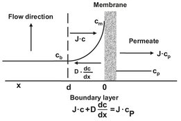
Fig. 12.9: Concentration polarization under steady state conditions.
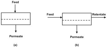
Fig. 12.10: Schematic of a dead-end (a) and cross-flow (b) module operation.
12.2.5 System design and cascades
A single membrane module or a number of such modules arranged in parallel or in series without a recycle constitutes a single-stage membrane separation process. The simplest design is the dead-end operation shown in Fig. 12.10a. For most industrial applications a cross-flow operation (Fig. 12.10b) is preferred because of the lower fouling tendency. Although counter-current flow gives the best performance in a cross-flow operation, most systems are designed with perfect permeate mixing. In a single-pass system the feed solution passes only once through the modules, and the volume of the feed decreases with path length. Multistage single-pass designs compensate for this loss of volume by arranging the modules in a tapered design. As shown in Fig. 12.11, the cross-flow velocity through the systems remains virtually constant by gradually reducing the number of modules in parallel.
The second system is the recirculation system or feed recycle system, where the feed is pressurized by a pump and allowed to pass several times through one stage, consisting of several modules. As shown in Fig. 12.12, each stage is fitted with a recirculation pump, which maximizes the hydrodynamic conditions. The feed recycle system is much more flexible than the single-pass system and is to be preferred in cases where severe fouling and concentration polarization occur. Often the single-stage design does not result in the desired product quality. The extent to which a feed mixture can be separated in a single stage is limited and determined by the separation factor. To achieve a higher degree of separation, a countercurrent cascade of stages, such as used in distillation, can be applied. In a cascade operation where the permeate of the first stage is the feed of the second stage and so on, it is possible to obtain a very high product purity. An example of a two-stage permeate enrichment operation is given in Fig. 12.13. The type of design depends on whether the permeate or the retentate is the desired product. When more stages are required, the optimization of the process becomes more complex and difficult because of the large number of variable involved.
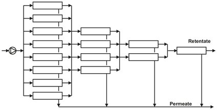
Fig. 12.11: Tapered design multistage single pass system.
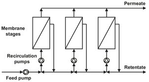
Fig. 12.12: Three-stage recirculation system.
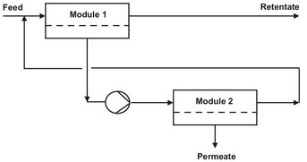
Fig. 12.13: Two-stage permeate-enriching cascade.