Process Technology: An Introduction - Haan A.B. 2015
13 Crystallization and precipitation
13.5 Crystallizer modeling and design
The final design of a crystallizer is the culmination of the design strategy depicted in Fig. 13.12. In the conceptual design stage, equilibrium data and operating mode (method of supersaturation generation) are surveyed. Solvent choice and processing conditions are determined in this step. Finally, after establishing the type of crystallizer, the crystallizer functional design is made. The use of mathematical models for the design of industrial crystallizers has lagged behind compared to other unit operations because of the complexities associated with rationally describing and interrelating growth and nucleation kinetics with the process configuration and mechanical features of the crystallizer. The design and analysis of crystallization processes for the continuous well-mixed suspension type have developed into formal design algorithms which can now be applied in situations of industrial importance. Examples of specific process configurations that can be modeled rigorously include fines destruction, clear-liquor advance, classified-product removal, vessel staging, and seeding. The basic requirement for these rigorous process configuration models is a population balance crystal size distribution algorithm.
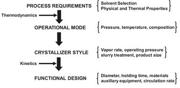
Fig. 13.12: Crystallization system design strategy.
13.5.1 Basic yield calculations
For crystallization a high recovery of refined solute is generally the desired design objective. The theoretical maximum product recovery or yield from the crystallizer is defined by
![]()
(13.12)
where the meaning of the quantities FS, XF, SS and XC are illustrated in Fig. 13.13 and defined as:
XF |
mass of dissolved solute in the feed per unit mass of solvent; |
XC |
mass of dissolved solute in liquid discharged from the crystallizer per unit mass of discharged solvent; |
FS |
mass feed rate of solvent into crystallizer; |
SS |
mass discharge rate of solvent leaving crystallizer. |
The solvent feed rate FS and the ratio of dissolved solute to solvent in the feed XF are usually fixed by upstream requirements. The composition of dissolved solute in the liquid leaving the crystallizer XC is determined by solubility, which is set by the temperature of the operation. The other adjustable variable is the solvent discharge rate SS. In evaporative systems, solvent is evaporated by adding heat to the system. Thus SS decreases and recovery increases as more solvent is evaporated and removed as a separate product stream. The conclusion from the preceding discussion is that for a given feed concentration and solubility relationship the mode of crystallizer operation governs the maximum recovery of solute. For a cooling crystallization system where no solvent is removed the only control that affects maximum solute recovery is crystallizer temperature. For evaporative systems, recovery is influenced by both the system temperature and by the quantity of solvent vaporized and removed from the system.
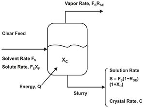
Fig. 13.13: Mass balance for a binary crystallization system.
For a system in which a pure solid component is crystallized by cooling or evaporation, the overall mass balance provides the maximum solute yield and total suspended solids concentration. RSE is the ratio of the mass of solvent evaporated per unit mass of solvent fed, whereas S and C are the solution and crystal removal rate. From the overall material balance it follows that
![]()
(13.13)
and the solution removal rate becomes
![]()
(13.14)
For FS = 1 unit of mass, substitution of (13.14) into (13.13) gives the crystal production rate C:
![]()
(13.15)
The maximum yield is now defined by
![]()
(13.16)
which can be simplified for specific operating modes:
cooling crystallization only:
![]()
(13.17)
evaporation only:
![]()
(13.18)
The preceding expressions can be solved provided the composition of the exit stream is known. In many instances it is acceptable to assume that the exit stream composition corresponds to saturation conditions. Systems in which this occurs are said to exhibit fast growth or Class II behavior. Should growth kinetics be too slow to use all the supersaturation, the system is said to exhibit slow-growth behavior and is classified as a Class I system.
13.5.2 Population balances
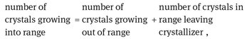
An analysis of a crystallization system requires the quantification of nucleation and growth kinetics, mass and energy balances, and the crystal size distribution. There are a number of ways of describing the crystal size distribution for a crystallizer. Population balances are the major theoretical tool for predicting and analyzing crystal size distributions. They allow one to quantify the nucleation and growth processes by balancing the number of crystals within a given size range. A balance on the number of crystals in any size range, say L1 to L2, accounts for crystals that enter and leave the size range by convective flow into and out of the control volume VT, and for crystals that enter and leave the size range by growth. Crystal breakage and agglomeration are ignored, and it is assumed that crystals that are formed by nucleation are near to size zero. The number of crystals in the size range L1 to L2 is given by

(13.19)
The population balance differs from a mass balance in that only the item balanced within a given size range is included, which is coupled to the more familiar balances on mass and energy. It is assumed that the population distribution is a continuous function and that a characteristic dimension L can describe crystal size, surface area, and volume. Population balances for crystallizers are usually described by the population density n that gives the number of crystals dN in the size range L to L + dL by
![]()
(13.20)
where Δ N is the number of crystals in size range Δ L per unit volume. The value of N depends on the value of L at which the interval dL is measured, as shown in Fig. 13.14. It is important to note that either clear liquor volume or slurry volume can be taken as a basis for the definition of n.
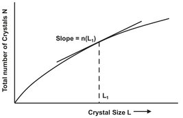
Fig. 13.14: Schematic representation of the population density.
13.5.3 The well-mixed MSMPR crystallizer
Application of the population balance is most easily described for the idealized case of a continuous, steady state MSMPR (mixed-suspension mixed-product removal) crystallizer shown in Fig. 13.15. The assumptions made are that no crystals are present in the feed stream, that all crystals are of the same size, and that crystal growth rate is independent of crystal size. For a well-mixed and constant slurry volume Vs in a crystallizer the population balance for a time interval Δ t and size range Δ L = L2-L1 becomes
(13.21)
which becomes in symbols
![]()
(13.22)
where Q is the volumetric feed and discharge rate, G is the growth rate (dL/dt), and n is the average population density for this size range. Many industrial crystallizers are operated in a well-mixed manner, and the form of crystal size distribution produced by such systems is fixed.
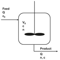
Fig. 13.15: Schematic diagram of a simple perfectly mixed crystallizer.