Process Technology: An Introduction - Haan A.B. 2015
2 The structure of chemical and biochemical process systems
2.3 Unit operations
Despite the very large number of chemical processes and products, there are only a modest number of different kinds of chemical process steps. This has allowed an economical method of organizing the field of chemical engineering into manageable segments. These segments are called unit operations and have been defined on two principles:
· (1) Although the number of individual processes is large, each one can be broken down into a series of operations that appear in process after process.
· (2) The individual operations are based on the same scientific principles. For example, in most processes solids and fluids must be moved, heat or other forms of energy must be transferred from one substance to another, and tasks like drying, size reduction, distillation, and evaporation must be performed.
Most of the unit operations are used to conduct the primarily physical steps of preparing the reactants, separating and purifying the products, recycling unconverted reactants, and controlling the energy transfer into or out of the chemical reactor. Typical examples are operations such as distillation, evaporation, liquid-liquid extraction, filtration, drying, heat exchange, mixing, classification, crystallization, and adsorption. When a process step involves a chemical change, it is sometimes called a unit process, or, more appropriately a chemical reaction step.
The consequence of this way of thinking is that a process designer regards a plant first and foremost as a collection of operations connected by a network of pipes. It requires a certain amount of thinking in systems to design a process optimally. The resulting network is called a flow chart. Such a flow chart generally contains the mass and energy balances for all the operations. As illustrated in Fig. 2.4, a flow chart can be quite complicated, the more so since every unit process can be regarded as a subsystem.
Because unit operations are a branch of engineering, they are based on both science and experience. Each process step can be carried out in a variety of equipment types. Theory and practice must combine to yield designs for equipment that can be fabricated, assembled, operated, and maintained. Usually the apparatus is chosen because it has some particular advantage in light of the properties of the materials being processed or the goal of the process step.
2.3.1 Reactors
The reactor in which the chemical reaction takes place occupies a central position in the chemical process. In size and appearance it may often seem to be one of the least impressive items of equipment, but its demands and performance are usually the most important factors in the design of the whole plant. The reactor provides the volume necessary for the reaction and holds the amount of catalyst required for the reaction. When a new chemical process is being developed, at least some indication of the performance of the reactor is needed before any economic assessment of the project as a whole can be made. An essential factor in this economic assessment is the formation of unwanted byproducts, which directly affect the operating costs of the process. In most cases the design of the reactor has a great effect on the amount of by-products formed and therefore the size of the separation equipment required. The design of a reactor and its mode of operation can thus have profound repercussions on the remainder of the plant.
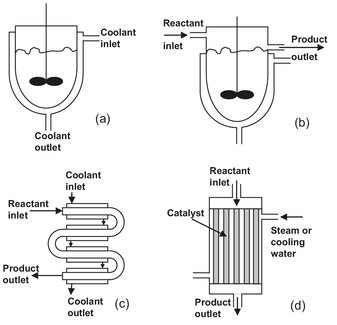
Fig. 2.5: Various common reactor types: (a) agitated batch reactor); (b) continuous stirred tank reactor; (c) tubular reactor; (d) multitubular packed bed reactor.
Fig. 2.5 shows several common types of reactors. The agitated batch reactor shown in (a) is an extremely common device. The jacket can be used to heat or cool the reactor, typically with steam or cooling water. The vessel may be built with thick walls so that the reactions can take place under pressure. There may be various ports for feed addition and product withdrawal. In many cases baffles are used on the inside to prevent vortexing of the liquid and to improve mixing. Normal construction materials include glass-lined steel, stainless steel, carbon steel, and various corrosion-resistant alloys. Internal cooling coils are sometimes used to provide additional heating or cooling capacity.
Sketch (b) shows a continuously stirred tank reactor. This is essentially identical to the agitated batch reactor but is operated continuously. Thus, feed and product are continuously added and removed. Obviously, it is not possible to operate this reactor in a way that every fluid molecule stays in for the same length of time. Fairly intense agitation is usually employed to keep the reactor content uniform. However, the degree of mixing decreases as the size of the reactor increases.
The tubular reactor shown in (c) is the most common type of reactor for reactions where large amounts of heat have to be supplied or removed. This can be achieved by burners or a heating/cooling fluid on the outside of the tubes. The tubular reactor is also widely used for highly exothermic solid-catalyzed reactions as multi-tubular packed bed reactor (d).
2.3.2 Recovery, purification, and fractionation technologies
Separation processes constitute more than half of the total equipment investment for the chemical and fuel industries. They are also widely used in pharmaceutical and food industries, mineral processing industry, and a variety of other industries. Separation processes may have a number of purposes, which can be loosely categorized as follows:
· — recovery or concentration: increasing the desired substance concentration in a solution, usually by removal of a substantial fraction of solvent;
· — purification: removal of impurities from the final product;
· — fractionation: separation of desired substances from one another.
Separating the desired product or products from the reaction mixture is often a complex and therefore expensive process. During the chemical and biochemical conversion mixtures are generated that contain many different components including the product, undesired side products, unconverted raw materials, solvents, catalysts, etc. All these components can exist in different states: gas, liquid, or solid. When all components are present in the same state, the mixture is called homogeneous. Typical examples are gas mixtures (air = oxygen + nitrogen + carbon dioxide) or liquid mixtures (sugar in water, ammonia in water, petrol, naphtha). If the components are present in different states, the mixture is called heterogeneous. Solid-liquid mixtures (melting ice, water-sand slurries), solid-gas mixtures (dust in air), and liquid-gas mixtures (droplets in air, bubbles in water) are typical examples of heterogeneous mixtures.
The separation of homogeneous mixtures and the separation of heterogeneous mixtures require totally different techniques and separation principles. Separation technologies for homogeneous mixtures are used to separate on a molecular basis and therefore referred to as molecular separations. Technologies for heterogeneous mixtures are usually called mechanical separations, because they are based on mechanical principles.
2.3.2.1 Molecular separation
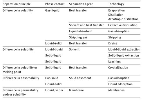
Homogeneous mixtures with a molecularly dispersed distribution of individual components can only be separated with a molecular separation process. In these processes mass and often heat is exchanged between at least two phases of different composition. The phases are the mixture phase(s) and a selective auxiliary phase. This auxiliary phase is generated by the introduction of an energy-separating agent such as heat and refrigeration, or by means of a mass-separating agent such as a solvent, adsorbent, or ion exchange resin. The separating agent serves to create the second phase and thereby form the required driving forces, concentration and temperature gradients. An overview of the main molecular separation technologies, their separation principle, and used separation agent is given in Tab. 2.1.
Tab. 2.1: Overview of main molecular separation technologies.
2.3.2.2 Mechanical separation
The separation of heterogeneous mixtures is usually accomplished by exerting forces on the mixture that has to be separated. These forces move the components comprising the mixture in such a way that a separation is obtained. Different forces are used in the different mechanical separation technologies:
· — gravity;
· — centrifugal;
· — impingement;
· — electrostatic;
· — magnetic.
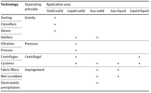
Many commercial separation operations also combine these separation principles, sometimes in the same apparatus, or otherwise in different pieces of equipment in series. An overview of the different mechanical separation technologies and their basic separation principles is given in Tab. 2.2.
Tab. 2.2: Overview of the main mechanical separation technologies and their application areas.
2.3.3 Product finishing operations
In recent decades, the chemical industry has moved away from commodity chemicals towards products of higher added value such as specialty chemicals and consumer products. These materials are often complex multiphase materials such as pharmaceutical pills and creams, cosmetic creams and lotions, ceramic and plastic products, ice cream and margarine, industrial paints and adhesives, fertilizer granules, etc. The quality and properties of these products is no longer solely determined by the concentrations achieved in the separation operations. End-consumers generally judge products according to their end-use properties, such as taste, smell, feel, and handling properties rather than their chemical composition. These end-use properties are typically linked to chemical and biological stability, degradability, chemical, biological, and therapeutic activity, aptitude to dissolution, mechanical, rheological, electrical, thermal, optical, magnetic characteristics for solids and solid particles together with size, shape color, touch, handling, cohesion, friability, rugosity, tastes, succulence, esthetics, sensory properties, etc.
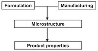
Fig. 2.6: Influence of formulation and processing on product properties.
An important characteristic of these industrial products is that they all possess a significant microstructure which is, as illustrated by Fig. 2.6, very dependent upon the product formulation (recipe) as well as the manufacturing conditions (technologies, process). Product-finishing technologies are concerned with physical or physicochemical principals, which add value to a product. Typical engineered products are:
· — structured solids such as catalyst carriers and coated pharmaceuticals. A catalyst carrier must be of a given shape and must have a defined porosity and inner surface with a given pore-size distribution. Coated pharmaceutic granules may have an improved taste and often release their active ingredients in a controlled and retarded way;
· — particulate solid systems concern crystalline, polymeric or amorphous solids that represent over 60 % of all products that chemical companies sell to their customers. Examples are fertilizers which have to be stored without caking and which have to be handled and applied without dust formation. Other solid systems are some pharmaceuticals and vitamins which have to be specially formulated to guarantee their bioavailability. These materials need to have a clearly defined physical shape in order to meet the designed and the desired quality standards;
· — emulsions, colloids, dispersions, suspensions, sprays, gels and foams concern complex media for which rheology and interfacial phenomena play a major role. Also involved are the so-called “soft solids” systems, which have a detectable yield stress, such as ceramic pastes, foods or drilling muds.
The main characteristics of product-finishing technologies are that quite different unit operations are used, involving less reaction and separation tasks and more structuring and stabilization tasks. Structuring processes are the opposite of separation processes. Man-made structured products use assembly, structuring, or texturizing processes, for example crystallization and emulsification processes (e.g. margarine, mayonnaise, ice cream, paint, detergent), foaming (e.g. insulating materials, shaving cream, whipped cream), precipitation, granulation, agglomeration, drying, extrusion, compression, prilling, shaping, micronisation, dough-making, baking, etc. The end-product is often a complex microstructure of dispersed phases held together by binding forces and a continuous phase. The product microstructure leads to the desired product functionality in use. Stabilization processes are the opposite of transformation processes. Two major processes can be identified. The first, encapsulation, provides a barrier between two reacting species, e.g. to preserve the integrity of the ingredients or accomplish intelligent functions such as controlled reactivity or programmed release of active components that may be obtained by multiple layer coatings. The second, to combat spoilage, is rather typical for the food industry and pharmaceutical products. Naturally structured foods often use preservation or stabilization processes in which the main aim is to eliminate microbial, enzymatic, or chemical spoilage of the raw materials, which are usually food tissues (fish, meat, vegetables).
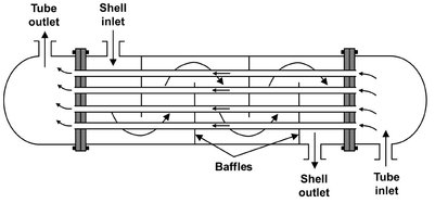
Fig. 2.7: Schematic of a single-pass countercurrent shell-and-tube heat exchanger.
2.3.4 Other important process units
In addition to purification and reaction, chemical processes usually include steps to heat or cool process streams and devices to move fluids. Heating and cooling devices include furnaces, air coolers, and heat exchangers. Furnaces and air coolers are familiar from one’s experience with automobile radiators, household furnaces, refrigerators, and air conditioning units. Fluid-to-fluid heat exchangers are not so familiar, but they are very common in chemical processes. The most common of these heat exchangers, the shell-and-tube heat exchanger, is shown in Fig. 2.7. In this unit, one fluid flows through the shell over the outside surfaces of the tubes. Baffles are usually used to increase the velocity of the fluid passing through the shell. A second fluid enters the tubes, flowing through them in parallel in one or more passes. As it flows through the exchanger, the cold fluid is heated by heat which is transferred through the tube walls. At the same time, the hot fluid is cooled. The figure shows inlet and exit nozzles for two fluid streams. These streams could be gas or liquid and could change phase within the heat exchanger.
Fluid motion in chemical processing is generally produced by pumps or, if gases are being moved, by blowers and compressors. The most common type of pump is the centrifugal pump shown in Fig. 2.8a. Liquid flows into this pump and is accelerated into high-speed circular motion by the vanes of the pump impeller. The liquid exits into the pump volute, where it slows down, converting at least part of the kinetic energy into pressure. Because of the mechanism of its operation, the performance of this pump is sensitive to the pressure which it develops. The higher the pressure rise across the pump, the lower is the pump capacity. Thus, the pressure which the pump produces will decrease as the throughput through the pump is increased. Pump efficiency also depends on the flow rate. The other common type of liquid pump is a positive displacement pump illustrated in Fig. 2.8b. Its capacity is directly related to the volume swept out by a piston operating in a cylinder, or to the frequency with which a gear tooth enters the cavity between the other identical teeth. Pressure rise has much less of an effect on the capacity of positive displacement pumps.
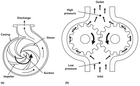
Fig. 2.8: Schematic of a centrifugal (a) and positive displacement pump (b).
Gas compressors operate on the same principle as do liquid pumps, but usually handle larger volumes and operate at higher speeds. Since large amounts of work are used to compress gases, cooling is usually needed during and after compression. Reciprocating, centrifugal, and axial-flow compressors are commonly used in the chemical process industries. Fig. 2.9 shows a schematic of a double-piston gas compressor used in the high-pressure polyethylene process for the compression of ethylene in multiple stages up to pressures of 3000 bar with cooling in between the stages.
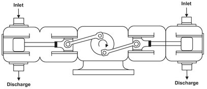
Fig. 2.9: Schematic of a double-piston compressor.