Process Technology: An Introduction - Haan A.B. 2015
17 Hydrodynamic aspects of scale-up
17.2 Mixing and stirring
17.2.1 Basic principles
Mixing is an important unit operation carried out to homogenize materials in terms of concentration of components, temperature, and physical properties, to intensify heat transfer, and to create dispersions, suspensions, or emulsions of mutually insoluble phases. The resulting mixture will always be homogeneous on a certain scale, while on a molecular level it will always be inhomogeneous. The quality of mixing is given by the degree of segregation IS given in eq. (17.2):
![]()
(17.2)
where c represents the concentration at a certain time and place and c* the arithmetic mean concentration. If IS equals 1, the mixture is completely segregated (not homogeneous at all). If IS equals zero, it is homogeneous on a molecular level. For most commercial operations a value of 10—4 is sufficient.
Mixing in an agitated tank is considered to occur at the macro— and the micro level. Macro mixing is established by the mean convective flow pattern. When macroscale variables are involved, every geometric design variable can affect the role of shear stresses. They can include items as power, impeller speed, impeller diameter, impeller blade shape, impeller blade width, height, or thickness, number of blades, impeller location, baffle location, and number of impellers. Mixing time will also have an influence on the final result, i.e. reactant conversion and/or selectivity.
Micro-scale variables are involved when the particles, droplets, baffles, or fluid clumps are on the order of 100 µm or less. In this case, the critical parameters are usually power per unit volume, distribution of power per unit volume between the impeller and the rest of the tank, velocity fluctuation, energy spectra, dissipation length, the smallest microscale eddy (swirl) size for the particular power level, and viscosity of the fluid. Micromixing occurs by turbulent diffusion and is primarily dependent on the energy dissipation per unit volume. The mixing energy is transferred from the largest eddies to the smallest ones until it is eventually dissipated through friction in viscous and turbulent shear stresses and finally appears as heat in the system. Of course, the rate of turbulent flow is greatest close to the impeller. Here, there is a high shear rate due to the trailing vortices associated with all impellers. Furthermore, a high proportion of the energy introduced by the impeller is dissipated here. In general, the specific energy dissipation around the impeller is approximately 100 times higher than in the rest of the tank. This results in a velocity fluctuation ratio to the average velocity in the order of 10:1 between the impeller zone and the rest of the tank. Thus the rate of homogenization of miscible liquids is greatest in this region, and gas and liquid-liquid dispersion occurs predominantly here.
Therefore processes which are particularly dependent on turbulent eddies and their associated forces are likely to be well correlated by the energy dissipation rate. Bubble formation and micromixing fall in this category. However, processes which are dependent on anisotropic main flow and for which the nonhomogeneous nature of stirred tanks turbulence is significant, e.g. solid suspension and solid-liquid mass transfer, are not well correlated that way. These processes primarily benefit from a longer mixing time.
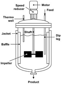
Fig. 17.3: Characteristic features of an agitated vessel.
17.2.2 Liquid mixing equipment
17.2.2.1 Mechanically agitated vessels
Agitated vessels are frequently used in batch as well as continuous service. Liquids are most often agitated in some kind of tank or vessel, usually cylindrical in form and with a vertical axis. The proportions of the tank vary widely, depending on the nature of the agitation problem. A standardized design such as that shown in Fig. 17.3 is applicable in many situations. The tank bottom is rounded and not flat, to eliminate sharp corners or regions into which fluid currents would not penetrate. The liquid depth is approximately equal to the diameter of the tank. Mechanical agitation utilizes a rotating impeller immersed in the liquid to accomplish the mixing and dispersion. The impeller is mounted on a shaft supported from above, which is driven by a motor that is sometimes directly connected to the shaft but more often through a speedreducing gearbox. Accessories such as inlet and outlet lines, coils, jackets, and wells for thermometers or other temperature-measuring devices are usually included. The design of the mixer can be based on the discharge capacity of the propeller, and on liquid entrainment in relation to the tank volume and desired blending time. The operating conditions are chosen to maximize the liquid throughput at a given power. This is achieved by a large stirrer diameter and a low stirrer speed.
The impeller causes the liquid to circulate through the vessel and eventually return to the impeller. If an axially positioned stirrer is operated in a vessel without inserts, the liquid is set into rotation, and a vortex is formed. This is generally undesirable, because gas can be entrained in the liquid, the degree of filling is reduced, and bulk rotation of the liquid counteracts mixing. In large tanks with vertical agitators the preferred method of reducing rotation and vortex formation is to install baffles, which impede rotational flow without interfering with radial or longitudinal flow. Installing vertical strips on the wall of the tank attains a simple and effective baffling. The standard baffle configuration consists of four vertical plates having a width equal to 8—10 % of the tank diameter. A small spacing between baffles and the tank wall is allowed to minimize dead zones particularly in solid-liquid systems. Although the presence of wall baffles causes an increase in power consumption, it generally enhances the process result.
17.2.2.2 Impeller types
Some of the commonly used impeller agitators are shown in Fig. 17.4. They are divided into two classes. Those that generate fluid flow parallel with the axis of the impeller shaft are called axial-flow impellers, and those that generate flow in a radial or tangential direction are called radial-flow impellers. The three main types of impeller for low to moderate viscosity liquids are propellers, turbines, paddles, and high-efficiency impellers. A propeller is an axial-flow high-speed impeller that is suitable for bulk mixing of low viscosity liquids. Flat-bladed turbines are essentially radial-flow devices, suitable for processes controlled by turbulent mixing. Anchor and helical ribbon agitators and other special shapes are used for more viscous fluids. The diameter of the helix is very close to the inside diameter of the tank. To provide good agitation near the floor of the tank, an anchor impeller may be used. Because it creates no vertical motion, it is a less effective mixer than a helical ribbon, but it promotes good heat transfer to or from the vessel wall.
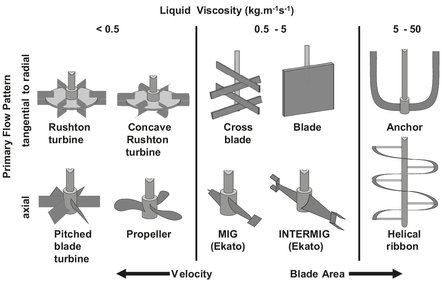
Fig. 17.4: Schematic of important industrial impeller types.
17.2.2.3 Flow patterns
As mentioned in the previous paragraph the two main classes of turbine impellers are based on the flow patterns they generate: axial flow and radial flow. Axial flow impellers produce a flow pattern involving the full tank volume as a single stage (Figs. 17.5b and c). Radial flow impellers, however, produce two circulating loops, one below and one above the impeller (Figs. 17.5a and d). Mixing occurs between the two loops, but less intensely than within each loop. These differences in flow patterns cause variations in the shear rate distributions in the tank, so that the mixing result is highly impacted by the impeller flow patterns. The flow patterns within a given impeller type are altered by parameters such as impeller diameter, liquid viscosity, and the use of multiple impellers. For example, the flow pattern with a pitched blade turbine becomes closer to radial as the impeller diameter is increased or as liquid viscosity increases. Multiple impellers are used when the liquid depth-to-tank diameter ratio is higher than 1. In that case more circulation loops are formed, e.g. two loops with two pitched blade turbines (Fig. 17.5d).
17.2.2.4 Static mixers
Inline motionless mixers derive the motion or energy dissipation needed for mixing from the flowing fluid itself. These mixers include orifice mixing columns, mixing valves, and static mixers. Static mixers are used in the chemical industries for plastics and synthetic fibers, e.g. continuous polymerization, homogenization of melts, and blending of additives in extruders, food manufacture, heat transfer, cosmetics, etc. These motionless mixers provide complete transverse uniformity and minimize longitudinal mixing, and therefore their performance approaches perfect plug flow conditions. Static mixers are usually classified as operating either under laminar or turbulent flow conditions. They consist of repeated structures called mixing elements attached inside a pipe. There are many proprietary designs, of which a few are shown in Fig. 17.6. These mixing elements generate a process of division, rotation, and reversal of fluid that create shear and mixing. Homogeneity is accomplished by alternate division and recombining of fluids passing through (Fig. 17.7). The number of layers produced equals 2”, where n is the number of elements. The mixing is therefore a progressive phenomenon because the specific surface increase is proportional to the specific surface already created. This results in an exponential increase of the mixing process in time and is an example of the so-called distributive mixing (exchange of layers). As a result they create a shearing action at the cost of pressure drop that causes mixing of single— and multiphase systems.
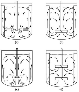
Fig. 17.5: Flow patterns with different impeller types, sizes and liquid viscosity: (a) flat blade turbine; (b) pitched blade turbine; (c) propeller; (d) two-pitched blade turbines.
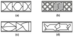
Fig. 17.6: Some proprietary static mixer designs: (a) Kenics; (b) Koch/Sulzer SMX; (c) Komax; (d) Etoflo.
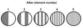
Fig. 17.7: Mechanism for laminar blending in Kenics static mixer. The grey zone represents liquid A and the white zone represents liquid B.
The energy consumed by a static mixer is given by P = Q*ΔPsm. A pump supplies the energy used to create the flow of the fluid Q through the mixer. For homogenization of two or more liquids, static mixers reduce the standard deviation or variance. The reduction of the variance is a product of the shear rate and time, and therefore equal to the ratio of the length over the diameter of the static mixer. The pressure drop over the static mixer Δ Psm depends on the flow rate and liquid viscosity. For a Kenics static mixer, ΔPsm is about six times that of an empty pipe in laminar flow. For a Koch/Sulzer SMX mixer it is 64 times higher.
17.2.3 Single phase systems
One of the most common mixing tasks is the mixing of two miscible liquids, this also being one of the most straightforward mixing problems. The main goal in this operation is to homogenize the mixture in order to improve heat transfor and/or mass transfer. The criteria used in selecting an impeller for these mixing operations are the power consumption and the mixing time. Multiplication of the power consumption with the mixing time will result in the total amount of energy used in the mixing operation. It is desired to keep this amount as low as possible for a given system of liquids, while meeting the mixing requirements. In general, the required mixing energies will be higher if the liquids in the mixture do not have the same density, since these differences will tend to segregate the mixture. In a turbulent flow regime and at high power consumption, the standard impeller used is the Rushton turbine, while at low power, either a propeller or a hydrofoil is used. If mixing has to be performed in a transition range between laminar and turbulent flow, either migs or intermigs are used. At high viscosities, most often helical ribbons or anchors are used. This is done because other impellers will provide almost no fluid flow near the wall of the vessel. The helical ribbon is particularly favorable because it provides for better topto-bottom mass-transfer and can also generate a helix near the center of the vessel, where the liquid flows from the bottom of the vessel to the top.
17.2.4 Multiphase systems
For multiphase systems, the main goal in mixing tasks is to create a large area for mass transfer, which can lead to higher reaction rates, or speed up the dissolution of solids. Three cases are discussed in this section: mixing immiscible liquids, suspending solids, and dispersing gases in liquids.
17.2.4.1 Suspending solids
The suspending of solids is needed in, for example, the dissolution of solids and in reactions in the liquid phase with heterogeneous catalysts. For both of these tasks it is important to achieve a (reasonably) homogeneous suspension in order to speed up dissolution or to improve catalyst efficiency by reducing gradients in reactants. Most designs are based on the so-called Zwietering criterion in combination with the criterion of a homogeneous suspension. The Zwietering criterion states that the solids in the suspension will be on the bottom not longer than one second to ensure good suspension. Research usually concentrates on determining the critical rotation speed needed for suspending the solids, as illustrated by Fig. 17.8. The default impeller used is the pitched blade turbine, relatively close to the bottom of the tank, in combination with a tank without a flat bottom to prevent the formation of dead zones where solids will hardly move.
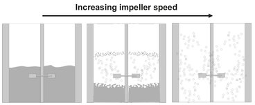
Fig. 17.8: Schematic of effect impeller speed on suspension of particles in a liquid.
17.2.4.2 Immiscible liquids
The mixing of immiscible liquids can take place, for example, in extraction. The main goal is to speed up mass transfer between the two phases by increasing the mass transfer area, thus achieving a larger recovery in the time available or shortening the mixing time needed to meet the criteria. The interfacial area is increased by the breakup of droplets of one of the fluids, the so-called disperse phase. A dispersion always consists of a continuous phase and a disperse phase (see Fig. 17.9.).
Depending on the viscosities of the two phases involved, break-up of the droplet will evolve in different ways. If the viscosities are almost identical, droplets will break into only a few smaller droplets (see Fig. 17.10), and the increase of interfacial area will be relatively slow. If the viscosity of the dispersed phase is low, compared to the continuous phase, several smaller droplets will be formed, and the area will increase significantly.
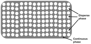
Fig. 17.9: Schematic representation of a dispersion.
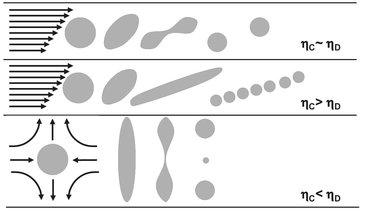
Fig. 17.10: Break-up mechanisms for different viscosities.
As in single phase liquid mixing, the standard impeller used is the Rushton turbine. Scale-up, however, is more complicated, due to several factors. The emulsion created, which consists of a continuous phase in which the second phase is finely dispersed as droplets, is very sensitive to impurities present. Some substances, the so-called surfactants (like soap), have an enormous effect on the stability of the emulsion. It is also desired to know which of the two liquids will be the continuous phase, because the process conditions depend to a large extent on this. As a rule of thumb, it can be presumed that the phase in which the impeller starts up will be the continuous phase. Concentration gradients, for example, will be smaller for the continuous phase, so if a parameter constant should be constant (the pH, for example), this phase should be the continuous phase. If in the case of a desired constant pH with a dispersed water phase, a base is added to increase the pH, and there will be droplets of base present in the mixture (with very high pH) and droplets of the original water phase (with a low pH). The pH of the droplets will only change if a droplet of base and a droplet with low pH coalescence, which is a very slow process. If water is the continuous phase, the base will be equally distributed within the mixture in a very short time, and pH will remain high. It is also important to know at which conditions phase-transition takes place. At different volume ratios, different phases will most likely be the continuous phase, and a very fast change of these phases can occur. The transition can take place under the influence of changes in temperature, volume ratio, and solute concentrations. For these reasons the design should be preferably based on the scale-up of pilot plant results.
17.2.4.3 Gases in liquids
In gas-liquid mixing, the main goal is the same as in liquid-liquid mixing: to create a large mass transfer area. Most applications involve reactions between a gas and a liquid, for example in hydrogenation, oxidation, and fermentation (where air is provided to the microorganisms). In this mixing operation, the power input to achieve a certain degree of mixing is (roughly) independent of the impeller type. In practice an impeller is operated at high rotation speed to obtain a homogenous dispersion of the gas over the vessel (Fig. 17.11). Often the Rushton turbine is used, because it is relatively cheap, but hydrofoils and concave Rushton turbines are also used. The position of the gas inlet, however, has a very large influence on the quality of mixing. If the inlet is positioned close to the surface of the liquid, almost no entrainment of gas takes place, and mixing is very poor. If the inlet is positioned very close to and below the impeller, an almost homogeneous dispersion of very fine gas bubbles is achieved.
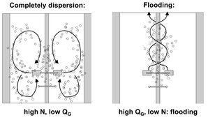
Fig. 17.11: Effect of rotation speed and gas flow on gas dispersion in a liquid.
17.2.5 Scale-up and scale-down procedures
The main objective of scale-up is to achieve the same quality of mixing in a commercial-size mixing tank as in a laboratory tank, or at least have an understanding of the differences expected in the commercial installation. Unfortunately, it is not possible to maintain the same combination of flow and shear distributions in commercial mixers as in small-scale tanks. Several scale-up methods have been developed depending on the process type and mixing requirements, but all methods emphasize geometric similarity. Otherwise correction factors are required which lead to high uncertainties in the prediction of the process result. Geometric similarity refers to maintaining the same impeller type, and relative dimensions of impeller, liquid height, and baffles. Two aspects of scale-up frequently arise. One is building a model based on pilot plant studies which develop an understanding of the process variables for an existing full-scale mixing installation. The other is taking a new process and studying it in a pilot plant in such a way that pertinent scale-up variables are worked out for a new mixing installation. There are a few scale-up principles that can indicate which approach to take in either case. Using geometric similarity, the macroscale variables can be summarized:
· — Blend and circulation times in the large tank will be much longer than in the small tank.
· — The maximum impeller zone shear rate will be higher in the larger tank, but the average impeller zone shear rate will be lower; therefore, there will be a much greater variation in shear rates in a full-scale tank than in a pilot unit.
· — Reynolds numbers in the large tank will be higher, typically in the order of 5—25 times higher than those in a small tank.
· — Large tanks tend to develop a recirculation pattern from the impeller through the tank back to the impeller. This results in a behavior similar to that for a number of tanks in a series. The net result is that the mean circulation time is increased over what would be predicted from the impeller pumping capacity. This also increases the standard deviation of the circulation times around the mean.
· — Heat transfer is normally much more demanding on a large scale. The introduction of helical coils, vertical tubes, or other heat transfer devices causes an increased tendency for areas of low recirculation to exist.
· — In gas-liquid systems, the tendency for an increase in the gas superficial velocity upon scale-up can further increase the overall circulation time.