5 Steps to a 5: AP Physics 2: Algebra-Based 2024 - Jacobs Greg 2023
STEP 4 Review the Knowledge You Need to Score High
14 Geometric and Physics Optics
IN THIS CHAPTER
Summary: This chapter reviews some of what you learned about mechanical waves in AP Physics 1 and then extends your knowledge to include electromagnetic waves. We’ll talk about interference, diffraction, reflection, refraction, and optics.

Key Ideas
![]() Waves are a disturbance in a medium that transports energy.
Waves are a disturbance in a medium that transports energy.
![]() Light is an electromagnetic wave that can travel through a vacuum.
Light is an electromagnetic wave that can travel through a vacuum.
![]() Electromagnetic waves are created by oscillating charges.
Electromagnetic waves are created by oscillating charges.
![]() The speed of a wave is constant within a given material. When a wave moves from one material to another, its speed and its wavelength change, but its frequency stays the same.
The speed of a wave is constant within a given material. When a wave moves from one material to another, its speed and its wavelength change, but its frequency stays the same.
![]() Interference patterns can be observed when a wave goes through two closely spaced slits or even a single slit.
Interference patterns can be observed when a wave goes through two closely spaced slits or even a single slit.
![]() Interference patterns can also be observed when light reflects off of a thin film.
Interference patterns can also be observed when light reflects off of a thin film.
![]() Waves can bend around corners and spread out when passing through an opening. This is called diffraction and is a natural behavior of all waves.
Waves can bend around corners and spread out when passing through an opening. This is called diffraction and is a natural behavior of all waves.
![]() The point source model, also known as Huygens’ principle, explains many of the unique behaviors of waves.
The point source model, also known as Huygens’ principle, explains many of the unique behaviors of waves.
![]() When waves encounter a boundary, they can transmit, reflect, and be absorbed. The transmitted wave always has the same frequency even when the wavelength and speed of the wave change.
When waves encounter a boundary, they can transmit, reflect, and be absorbed. The transmitted wave always has the same frequency even when the wavelength and speed of the wave change.
![]() Transverse waves can be polarized.
Transverse waves can be polarized.
![]() When light hits an interface between materials, the light reflects and refracts. The angle of refraction is given by Snell’s law.
When light hits an interface between materials, the light reflects and refracts. The angle of refraction is given by Snell’s law.
![]() Total internal reflection can occur when light strikes a boundary going from a higher-index material to a lower-index material at a large incident angle.
Total internal reflection can occur when light strikes a boundary going from a higher-index material to a lower-index material at a large incident angle.
![]() Concave mirrors and convex lenses are optical instruments that converge light to a focal point. Concave lenses and convex mirrors are optical instruments that cause light to diverge.
Concave mirrors and convex lenses are optical instruments that converge light to a focal point. Concave lenses and convex mirrors are optical instruments that cause light to diverge.
![]() Virtual images are formed right-side up; real images are upside down and can be projected on a screen.
Virtual images are formed right-side up; real images are upside down and can be projected on a screen.
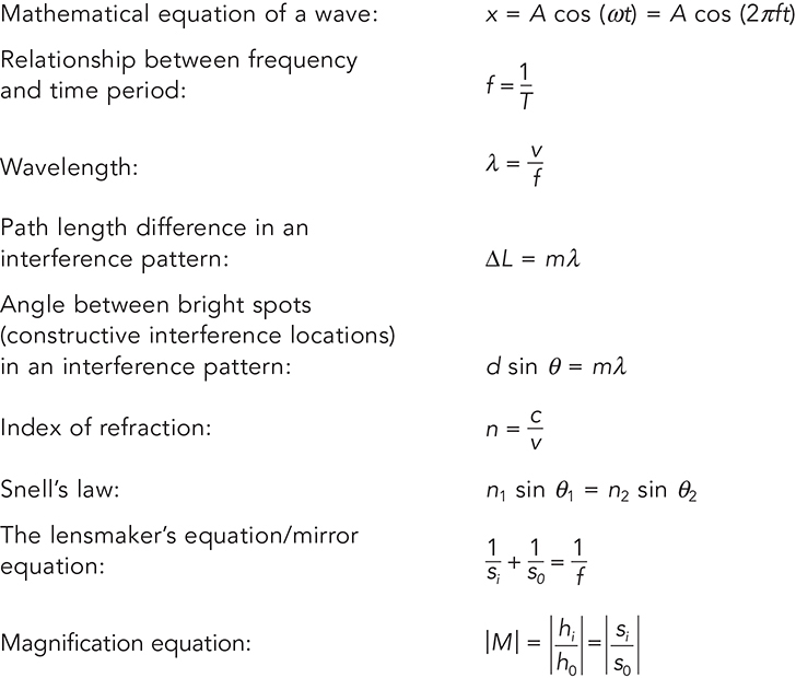
Relevant Equations
Transverse and Longitudinal Waves
Waves come in two forms: transverse and longitudinal.
Wave: A rhythmic oscillation that transfers energy from one place to another.
A transverse wave occurs when the particles in the wave move perpendicular to the direction of the wave’s motion. When you jiggle a string up and down, you create a transverse wave. A transverse wave is shown next.
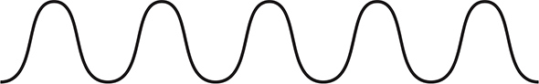
Longitudinal waves occur when particles move parallel to the direction of the wave’s motion. Sound waves are examples of longitudinal waves. A good way to visualize how a sound wave propagates is to imagine one of those “telephones” you might have made when you were younger by connecting two cans with a piece of string. When you talk into one of the cans, your vocal cords cause air molecules to vibrate back and forth, and those vibrating air molecules hit the bottom of the can, which transfers that back-and-forth vibration to the string. Molecules in the string get squished together or pulled apart, depending on whether the bottom of the can is moving back or forth. So the inside of the string would look like the next figure, in which dark areas represent regions where the molecules are squished together, and light areas represent regions where the molecules are pulled apart.
![]()
The terms we use to describe waves can be applied to both transverse and longitudinal waves, but they’re easiest to illustrate with transverse waves. Take a look at the next figure.
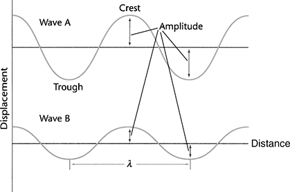
A crest (or a peak) is a high point on a wave, and a trough is a low point on a wave. The distance from peak-to-peak or from trough-to-trough is called the wavelength. This distance is abbreviated with the Greek letter λ (lambda). The distance that a peak or a trough is from the horizontal axis is called the amplitude, abbreviated with the letter A.
The time necessary for one complete wavelength to pass a given point is the period, abbreviated T. The number of wavelengths that pass a given point in 1 second is the frequency, abbreviated f. The period and frequency of a wave are related with a simple equation:
![]()
The Wave Equation
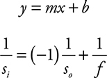
On the AP exam, you might be expected to look at a graph of a wave and produce the mathematical equation of the wave. It’s actually quite easy to do. Look at the equation of a wave on the equation sheet:
![]()
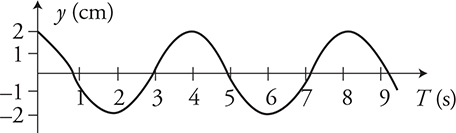
It looks kind of scary but no worries. All you have to do is fill in the blanks. Look at this graph of a wave in the figure above. What can we find on the graph?
1. amplitude: A = 2 cm
2. time period: T = 4 s (which means f = ¼ Hz)
Plug these into the wave equation: (2 cm) cos [2π(0.25 Hz)t] and we are done! OK, you might want to convert units and this is really not a cosine wave. It looks like a sine wave, but remember the only difference between sine and cosine is a phase shift. Your math teacher can tell you about phase shifts. The point is, don’t make it hard. Remember this is a timed exam. Answer the question and move on.
Interference
When two waves cross each other’s path, they interact with each other. There are two ways they can do this—one is called constructive interference, and the other is called destructive interference.
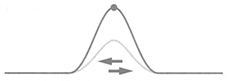
Constructive interference happens when the peaks of one wave align with the peaks of the other wave. So if we send two wave pulses toward each other, as shown below,
![]()
then when they meet in the middle of the string they will interfere constructively.
The two waves will then continue on their ways. This is one of the cool things about waves. Waves pass right through each other as if they never even met.
![]()
However, if the peaks of one wave align with the troughs of the other wave, we get destructive interference. For example, if we send the two wave pulses in the figure below toward each other,
![]()
they will interfere destructively,
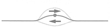
and then they will continue along their ways. Destructive interference does not destroy the wave. In destructive interference, the wave’s amplitude will be less while the waves occupy the same space. Once the waves pass each other, the amplitude goes back to normal as if the waves never met.
![]()
Electromagnetic Waves
When radio waves are beamed through space, or when X-rays are used to look at your bones, or when visible light travels from a lightbulb to your eye, electromagnetic waves are at work. All these types of radiation fall in the electromagnetic spectrum, shown below.

The unique characteristic about electromagnetic waves is that all of them travel at exactly the same speed through a vacuum—3 × 10⁸ m/s. The more famous name for “3 × 10⁸ m/s” is “the speed of light,” or “c.”
What makes one form of electromagnetic radiation different from another form is simply the frequency of the wave. AM radio waves have a very low frequency and a very long wavelength; whereas, gamma rays have an extremely high frequency and an exceptionally short wavelength. But they’re all just varying forms of light waves.
Remember that charges create an electric field around themselves that extends infinitely far away. When charges oscillate, they create a disturbance in the electric field they are producing that moves outward through the field. This is a wave!
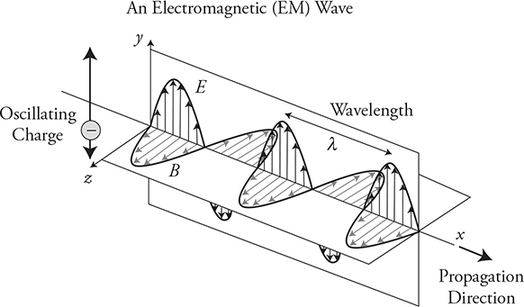
The really interesting part is that the oscillating electric field wave induces an oscillating magnetic field wave at a right angle to itself. This re-creates the electric field wave, and the whole thing keeps oscillating back and forth and never stops. This electromagnetic, or EM, wave is self-propagating and can travel through a vacuum at the speed of light. This is a major departure from mechanical waves, like sound, that require a physical medium to move through. Electromagnetic waves are produced by any oscillating charge. If you charge up a balloon and shake it around, you are producing an EM wave. Remember from thermodynamics we learned that atoms are in constant, random, oscillating motion. That means anything with a temperature above absolute zero—which is everything—will be radiating EM waves all the time. You are emitting infrared radiation right now. If we heat you up to about 1000°C, you will glow red!
Look back at the diagram of the EM wave. Notice that EM waves are transverse. This will be important in the next section.
Polarization
One of the interesting differences between transverse and longitudinal waves is polarization. First off, this is not the same polarization that we talked about in static electricity. That was charge polarization where a neutral object can be induced to have one side more positive and the other side more negative. Here we are talking about wave polarization.
Look back again at the picture of an EM wave. Notice how the electric portion of the wave is oscillating up and down in the y-direction? That is because the charge that created the E-Field wave was oscillating up and down as well. It is said to be polarized in the y-direction. If you want to polarize the E-Field portion of the wave horizontally, just wiggle the charge back and forth in the horizontal (z) direction. Another way we get polarized light is when it reflects off of flat surfaces, like the surface of a lake or a mirror. It tends to be polarized in the plane of the surface. If you drive a car, you know about road glare. The bright reflection off the road tends to be horizontally polarized.
Without going into any details, there are substances that will allow EM waves polarized in the y-direction to pass through them, but will absorb waves polarized in the z-direction. We use these in “polarized” sunglasses to block glare from the road and in 3D movies so that each eye sees only one of the two images projected onto the screen. Longitudinal waves cannot be polarized, because they vibrate forward and backward.
Here is a quick experiment you can perform: On a sunny day, put on polarizing sunglasses and look at the horizontal surface of a road or lake. Observe how the glasses block the horizontally polarized light reflecting from the surface. Now tilt your head sideways 90°. What will you see? Why do you now see so much glare from the surface? When you tilt your head 90° you align the transmission axis of the lenses with the axis of the polarized light reflecting from the surface and all the glare goes right through the sunglasses. If you only turn your head 45°, a portion of the glare gets through the glasses. When your head is vertical, the transmission axis of the glasses and the horizontally polarized light from the surface are at right angles, all of the glare is absorbed by the glasses and no glare gets through.
Diffraction and the Point-Source Model
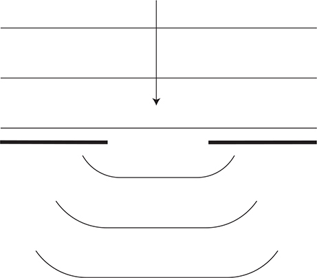
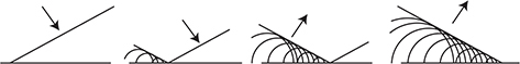
Have you ever wondered why you can hear sounds around corners? It’s not just due to waves reflecting off something. Even if you are in the middle of an open field, someone standing behind you can still hear you. The wave property called diffraction helps explain this phenomenon.
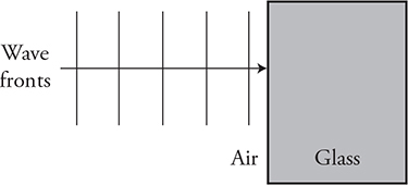
Look at the wave fronts traveling upward toward the top of the page in the diagram above. Notice how they all bend around the obstruction. Why does this occur? Huygens explained it this way: each point on a wave is the starting spot for a new wave. This is called the point-source model. So, each point of the wave that goes past a boundary is the new starting spot for a wave. These waves don’t just travel forward, they also travel outward to the sides as seen in this diagram below.
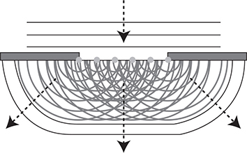
As a result, we can hear things around corners. If you are in the band, you know that the mouth of wind instruments curves outward to enhance diffraction, helping the sound to bend outward and fill the entire auditorium.
So we can hear things around corners but can’t see things around corners. Does this mean that light is not a wave? For years that was the argument, but it turns out that the smaller the wave is, compared to the boundary it is passing by, the less we see the effects of diffraction. In general, the wavelength of the wave needs to be about the same size as or larger than the obstacle, or we won’t get much diffraction. Visible light has a wavelength between 400 nm and 700 nm. That’s very small. So we would need an opening that is about that size or smaller before we would start to notice diffraction effects in visible light.
Single and Double Slits
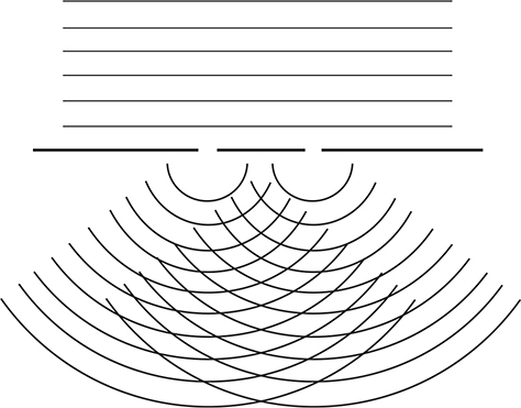
The way that physicists showed that light behaves like a wave was through slit experiments. Consider light shining through two very small slits, located very close together—slits separated by tenths or hundredths of millimeters. The light shone through each slit and then hit a screen. But here’s the kicker: rather than seeing two bright patches on the screen (which would be expected if light was made of particles), the physicists saw lots of bright patches. The only way to explain this phenomenon was to conclude that light behaves like a wave.
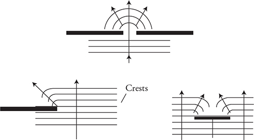
Look at the next figure. When the light waves go through each slit, they were diffracted. As a result, the waves that came through the top slit overlap with the waves that came through the bottom slit—everywhere that peaks or troughs crossed paths, either constructive or destructive interference occurred.
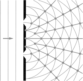
So when the light waves hit the screen, at some places they constructively interfered with one another and in other places they destructively interfered with one another. That explains why the screen looked like the following image.
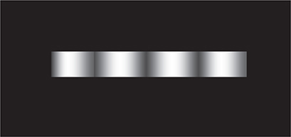
The bright areas were where constructive interference occurred, and the dark areas were where destructive interference occurred. Particles can’t interfere with one another—only waves can—so this experiment proved that light behaves like a wave.
When light passes through slits to reach a screen, the equation to find the location of bright spots is as follows:
![]()
Here, d is the distance between slits, λ is the wavelength of the light, and m is the “order” of the bright spot; we discuss m below. θ is the angle at which an observer has to look to see the bright spot.
The variable m represents the “order” of the bright or dark spot, measured from the central maximum as shown in the next figure. Bright spots get integer values of m; dark spots get half-integer values of m. The central maximum represents m = 0. The first constructive interference location to the side of the central maxima is called the first-order maxima and would be represented by m = 1. The second-order maxima would be m = 2, etc. The first destructive interference location at m = 1⁄2, would be the first-order minima.
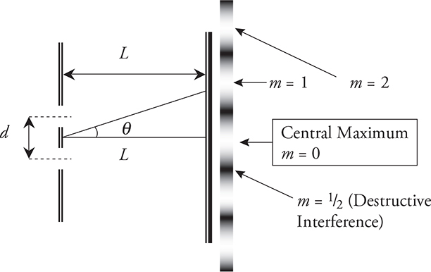
So, for example, if you wanted to find how far from the center of the pattern the first bright spot labeled m = 1 is, you would plug in “1” for m, If you wanted to find the dark region closest to the center of the screen, you would plug in “½” for m.
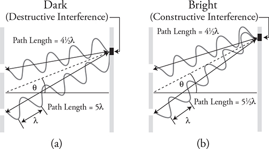
To better understand why waves produce this interference pattern but particles do not, look at the above diagram where the waves are shown oscillating toward the screen on the right.
Count the number of wavelengths from the top opening to the screen in figure (a): 4½ wavelengths. This is called the path length to the screen. Now count the path length from the bottom opening to the screen: 5 wavelengths. That means the waves will arrive ½ a wavelength off. Or, a crest of one wave is meeting a trough for the other wave, creating destructive interference, or a dark spot on the screen. Now look at figure (b). One wave travels 4½ wavelengths, while the other travels 5½ wavelengths. They are in phase and will have constructive interference, producing a bright spot on the screen.
The path length difference equation, ΔL = mλ, shows us that whenever the difference in the length to the screen ΔL is a whole multiple (m = 0, 1, 2, 3, 4, 5, etc.) of the wavelength, we will get constructive interference. When the waves are off by a ½ wavelength (m = ½, 3⁄2, 5⁄2, etc.), there will be destructive interference.
Single Slits and Diffraction Gratings
Once you understand the double-slit experiment, single slits and diffraction gratings are simple.
A diffraction grating consists of a large number of slits, not just two slits. The locations of bright and dark spots on the screen are the same as for a double slit, but the bright spots produced by a diffraction grating are very sharp dots.
A single slit produces interference patterns as well because the light that bends around each side of the slit interferes upon hitting the screen. For a single slit, the central maximum is bright and very wide; the other bright spots are regularly spaced, but dim relative to the central maximum.
Index of Refraction
Light also undergoes interference when it reflects off of thin films of transparent material. Before studying this effect quantitatively, though, we have to examine how light behaves when it passes through different materials.
Light—or any electromagnetic wave—travels at the speed c, or 3 × 10⁸ m/s. But it only travels at this speed through a vacuum, when there aren’t any pesky molecules to get in the way. When it travels through anything other than a vacuum, light slows down. The amount by which light slows down in a material is called the material’s index of refraction.
Index of refraction: A number that describes by how much light slows down when it passes through a certain material, abbreviated n. (Note: Index of refraction is a “naked number” without any units.)
The index of refraction can be calculated using this equation.
![]()
This says that the index of refraction of a certain material, n, equals the speed of light in a vacuum, c, divided by the speed of light through that material, v.
For example, the index of refraction of glass is about 1.5. This means that light travels 1.5 times faster through a vacuum than it does through glass. The index of refraction of air is approximately 1. Light travels through air at just about the same speed as it travels through a vacuum.

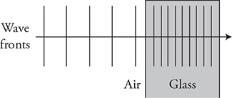
Another thing that happens to light as it passes through a material is that its wavelength changes. When light waves go from a medium with a low index of refraction to one with a high index of refraction, they get squished together. So, if light waves with a wavelength of 500 nm travel through air (nair = 1), enter water (nwater = 1.33), and then emerge back into air again, it would look like the figure below.

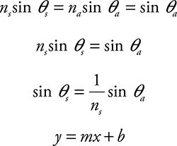
The equation that goes along with this situation is the following:
![]()
In this equation, λn is the wavelength of the light traveling through the transparent medium (like water, in the figure above), λ is the wavelength in a vacuum, and n is the index of refraction of the transparent medium.
It is important to note that, even though the wavelength of light changes as it goes from one material to another, its frequency remains constant. The frequency of light is a property of the photons that comprise it (more about that in Chapter 15), and the frequency doesn’t change when light slows down or speeds up.
Thin Films
When light hits a thin film of some sort, the interference properties of the light waves are readily apparent. You have likely seen this effect if you’ve ever noticed a puddle in a parking lot. If a bit of oil happens to drop on the puddle, the oil forms a very thin film on top of the water. White light (say, from the sun) reflecting off of the oil undergoes interference, and you see some of the component colors of the light.
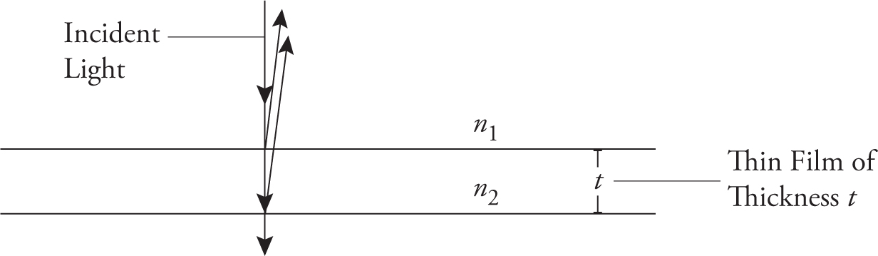
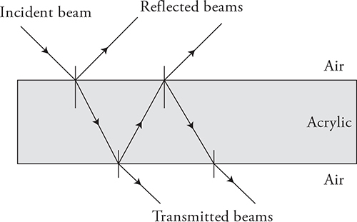
Consider a situation where monochromatic light (meaning “light that is all of the same wavelength”) hits a thin film, as shown in the next figure. At the top surface, some light will be reflected, and some will penetrate the film. The same thing will happen at the bottom surface: some light will be reflected back up through the film, and some will keep on traveling out through the bottom surface. Notice that the two reflected light waves overlap; the wave that reflected off the top surface and the wave that traveled through the film and reflected off the bottom surface will interfere.
The important thing to know here is whether the interference is constructive or destructive. The wave that goes through the film travels a distance of 2t before interfering, where t is the thickness of the film. If this extra distance is precisely equal to a wavelength, then the interference is constructive. You also get constructive interference if this extra distance is precisely equal to two, or three, or any whole number of wavelengths.
But be careful what wavelength you use . . . because this extra distance occurs inside the film, we’re talking about the wavelength in the film, which is the wavelength in a vacuum divided by the index of refraction of the film.
The equation for constructive interference turns out to be
![]()
where m is any whole number, representing how many extra wavelengths the light inside the film went.
So, when does destructive interference occur? When the extra distance in the film precisely equals ½ wavelength . . . or 1½ wavelengths, or 2½ wavelengths . . . so for destructive interferences, plug in a half-integer for m.
There’s one more complication. If light reflects off of a surface while going from low to high index of refraction, the light “changes phase.” For example, if light in air reflects off oil (n ~1.2), the light changes phase. If light in water reflects off oil, though, the light does not change phase. For our purposes, a phase change simply means that the conditions for constructive and destructive interference are reversed.
Summary: For thin film problems, go through these steps.
1. Count the phase changes. A phase change occurs for every reflection from low to high index of refraction.
2. The extra distance traveled by the wave in the film is twice the thickness of the film.
3. The wavelength in the film is ![]() , where n is the index of refraction of the film’s material.
, where n is the index of refraction of the film’s material.
4. Use the equation 2t = mλn. If the light undergoes zero or two phase changes, then plugging in whole numbers for m gives conditions for constructive interference. (Plugging in half-integers for m gives destructive interference.) If the light undergoes one phase change, conditions are reversed—whole numbers give destructive interference, half-integers, constructive.
Finally, why do you see a rainbow when there’s oil on top of a puddle? White light from the sun, consisting of all wavelengths, hits the oil. The thickness of the oil at each point allows only one wavelength to interfere constructively. So, at one point on the puddle, you see just a certain shade of red. At another point, you see just a certain shade of orange, and so on. The result, over the area of the entire puddle, is a brilliant, swirling rainbow.
Wave Behavior at Boundaries
When a light wave encounters a boundary, several things can occur:
1. The wave can be reflected back off the medium. Remember that when light reflects off of a surface while going from lower to higher index of refraction, the light “changes phase.”
2. If the new medium is transparent, the light can transmit through, carrying its energy with it.
3. Or, if the medium is opaque, the wave can be absorbed, giving up its energy to the medium, which will warm it up. (We already talked about this in Chapter 10.)
In reality, more than one of these can happen at the same time. Some of the wave can be absorbed, some transmitted, and some reflected. The key is that all of the wave energy goes somewhere. Nothing is gained or lost (conservation of energy).
The remainder of this chapter will concentrate on how light reflects and transmits when it encounters a new medium.
Reflection and Mirrors
Okay, time to draw some pictures. Let’s start with plane (flat) mirrors.
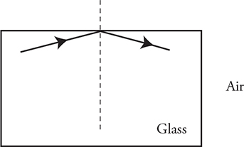
The key to solving problems that involve plane mirrors is that the angle at which a ray of light hits the mirror equals the angle at which it bounces off, as shown in the next figure.
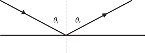
In other words—or, more accurately, “in other symbols”—θi = θr, where θi is the incident1 angle, and θr is the reflected angle. Notice how these two angles are measured between the ray and the dashed line. This dashed line is called “the normal line.” (In geometry and physics, a normal line means a perpendicular line.) In optics, we measure our angles from the normal line to the light ray.
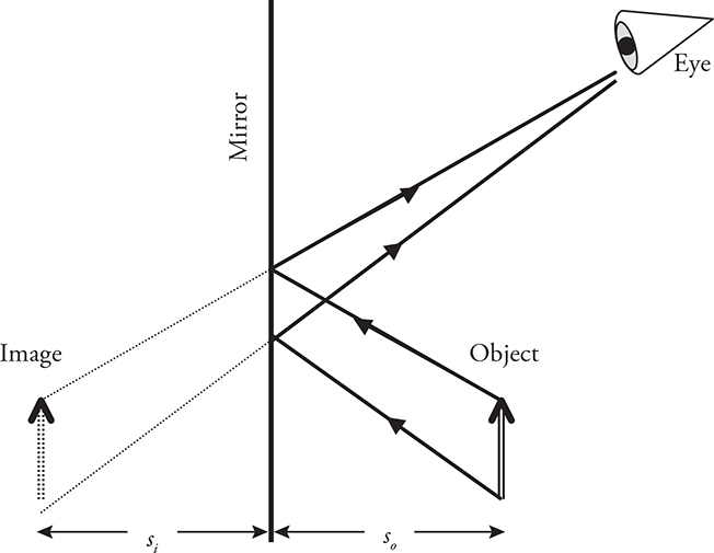
So, let’s say you had an arrow, and you wanted to look at its reflection in a plane mirror. We’ll draw what you would see in the following figure.
The image of the arrow that you would see is drawn in dotted lines. To draw this image, we first drew the rays of light that reflect from the top and bottom of the arrow to your eye. Then we extended the reflected rays through the mirror.
Whenever you are working with a plane mirror, follow these rules:
• The image is upright. Another term for an upright image is a virtual image.
• The image is the same size as the original object. That is, the magnification, m, is equal to 1.
• The image distance, si, equals the object distance, so.
A more challenging type of mirror to work with is called a spherical mirror. Before we draw our arrow as it looks when reflected in a spherical mirror, let’s first review some terminology (this terminology is illustrated in the next figure).
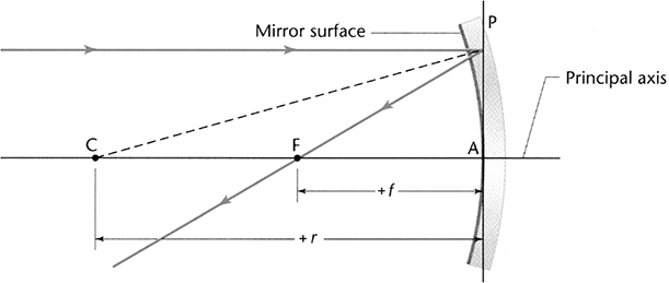
A spherical mirror is a curved mirror—like a spoon—that has a constant radius of curvature, r. The imaginary line running through the middle of the mirror is called the principal axis. The point labeled C, which is the center of the sphere, lies on the principal axis and is located a distance r from the middle of the mirror. The point labeled F is the focal point, and it is located a distance f, where f = (r/2), from the middle of the mirror. The focal point is also on the principal axis. The line labeled P is perpendicular to the principal axis.
There are several rules to follow when working with spherical mirrors. Memorize these.
• Incident rays that are parallel to the principal axis reflect through the focal point.
• Incident rays that go through the focal point reflect parallel to the principal axis.
• Any points that lie on the same side of the mirror as the object are a positive distance from the mirror. Any points that lie on the other side of the mirror are a negative distance from the mirror. Notice how the figure above shows a positive focal length and radius.
• 
That last rule is called the “mirror equation.” (You’ll find this equation to be identical to the “lensmaker’s equation” later.)
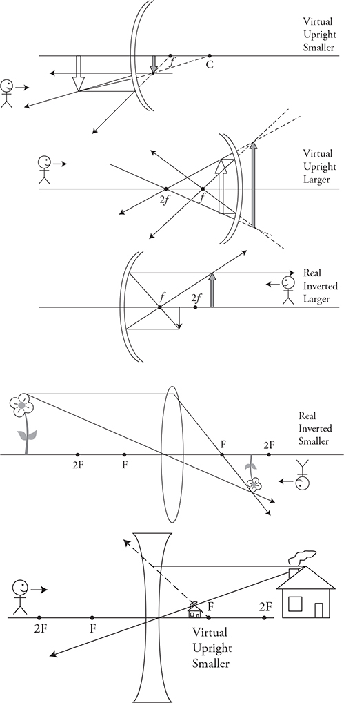
To demonstrate these rules, we’ll draw three different ways to position our arrow with respect to the mirror. In the first scenario, we’ll place our arrow on the principal axis, beyond point C, as shown in the following figure.
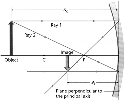
Notice that the image here is upside down. Whenever an image is upside down, it is called a real image. A real image can be projected onto a screen, whereas a virtual image cannot.2
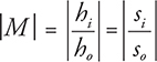
The magnification, m, is found by

When the magnification is less than 1, the image is reduced in size. A magnification of 0.5 would mean the image is 1/2 the size of the object. When the magnification is larger than 1, the image is bigger than the object. A magnification of 2.5 means the image is 2.5 times larger than the object. Plugging in values from our drawing above, we see that our magnification should be less than 1, which is exactly what our figure shows. Good for us!
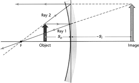
Now we’ll place our arrow between the mirror and F, as shown in the next figure. When an object is placed between F and the mirror, the image created is a virtual image—it is upright with a magnification greater than 1. Notice that the image distance will be negative because it is on the other side or opposite side of the mirror from the object.
Finally, we will place our object on the other side of the mirror, as shown in the next figure. Now we have a convex mirror, which is a diverging mirror—parallel rays tend to spread away from the focal point. In this situation, the image is again virtual with a magnification less than 1.
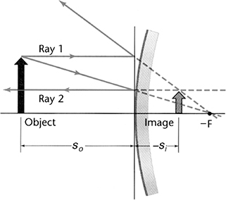
When we use the mirror equation here, we have to be especially careful: so is positive, but both si and f are negative, because they are not on the same side of the mirror as the object.
Note that the convex (diverging) mirror cannot produce a real image. Give it a try—you can’t do it!
Snell’s Law and the Critical Angle
Two things before we begin:
1. Remember that light can partially transmit into a new material, as well as partially reflect off the surface at the same time. You know this because you can see through a window and see your reflection in the window at the same time.
2. When light transmits into a new material, the index of refraction of the new medium determines the new velocity of the light,  , and the new wavelength of the light,
 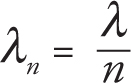 . The frequency of the light stays the same.
In addition to changing its speed and its wavelength, light can also change its direction when it travels from one medium to another. Snell’s law describes this behavior.
n1 sin θ1 = n2 sin θ2
To understand Snell’s law, it’s easiest to see it in action. The next figure should help.
In the figure, a ray of light is going from air into water. The dotted line perpendicular to the surface is called the normal.3 This line is not real; rather it is a reference line for use in Snell’s law. In optics, ALL ANGLES ARE MEASURED FROM THE NORMAL, NOT FROM A SURFACE!
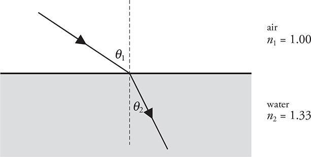
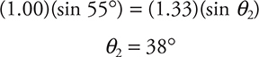
As the light ray enters the water, it is being bent toward the normal. The angles θ1 and θ2 are marked on the figure, and the index of refraction of each material, n1 and n2, is also noted. If we knew that θ1 equals 55°, for example, we could solve for θ2 using Snell’s law.
Whenever light goes from a medium with a low index of refraction to one with a high index of refraction—as in our drawing—the ray is bent toward the normal. Whenever light goes in the opposite direction from a larger index of refraction to a smaller index of refraction—say, from water into air—the ray is bent away from the normal.
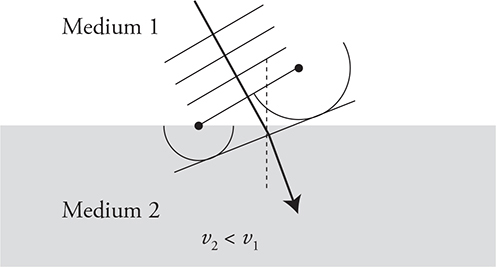
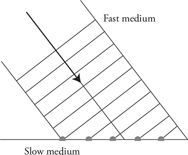
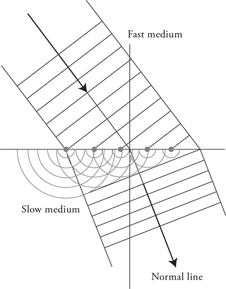
But why, you may be asking, does light change directions just because it moves into a new material? The point source model of waves (Huygens’ principle) tells us why. The waves moving through medium 1 are traveling faster than the waves traveling in medium 2. Using the endpoints of the wave front as point sources, we can draw the two waves that are produced. Notice how the wave in medium 1 is farther out because it is moving faster. When we connect these two point sources, the new wave front has changed direction. It’s heading in a new direction closer to the normal line. This happens because the wave slows down, resulting in an angle of refraction that is smaller than the angle of incidence.
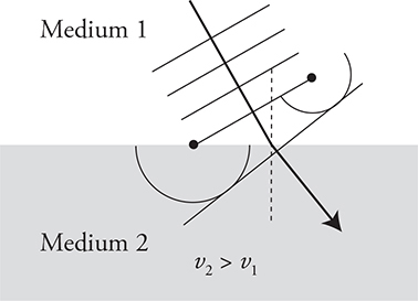
Now let’s reverse the situation. Medium 1 is the slow material and medium 2 is the fast medium. The effect is reversed. When the wave speeds up, it will turn away from the normal. It has to.
Here is another way to remember the “bending” rule. Bigger velocity of light means a bigger angle with the normal. Smaller velocity of light means a smaller angle with the normal.
There is only one exception to this rule! If light hits the new medium head-on (angle of incidence of 0°), it won’t change direction. It just plows straight into the new medium with no turning. You can prove that to yourself using the point-source model.
If you have a laser pointer, try shining it into some slightly milky water . . . you’ll see the beam bend into the water. But you’ll also see a little bit of the light reflect off the surface, at an angle equal to the initial angle. (Be careful the reflected light doesn’t get into your eye!) In fact, at a surface, if light is refracted into the second material, some light must be reflected.
Sometimes, though, when light goes from a medium with a high index of refraction to one with a low index of refraction, we could get total internal reflection. For total internal reflection to occur, the light ray must be directed at or beyond the critical angle.
Critical Angle: The angle past which rays cannot be transmitted from one material to another, abbreviated θc.
![]()
Again, pictures help, so let’s take a look at the next figure.
In this figure, a ray of light shines up through a glass block. The critical angle for light going from glass to air is 42°; however, the angle of the incident ray is greater than the critical angle. Therefore, the light cannot be transmitted into the air. Instead, all of it reflects inside the glass. Total internal reflection occurs anytime light cannot leave a material.
The next diagram shows a laser beam coming from the upper left shining on a glass block. We get to see all the behaviors of light in one image.
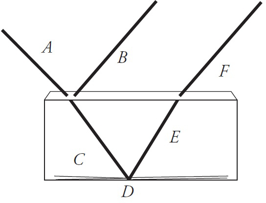
• First, the light ray A strikes the surface. Part of the light reflects, B, and part transmits, C. The reflected light, B, takes off at the same angle equal to the angle of incidence.
• The transmitted wave, C, refracts toward the normal because it is slowing down.
• None of the wave exits the bottom of the glass block. The angle of incidence must be larger than the critical angle. Total internal reflection occurs at point D.
• After reflecting off the bottom of the glass, the wave, E, strikes the top of the glass and refracts away from the normal, F, as the wave speeds back up when it reenters the air.
This could easily be the basis for a question on the AP exam.
Lenses
We have two types of lenses to play with: convex and concave. A convex lens, also known as a “converging lens,” is shown below.

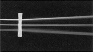
And a concave lens, or “diverging lens,” is shown in the next figure.
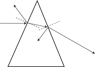
How do lenses work? Look at the prism in the following diagram. The ray coming from air on the left, turns toward the normal as it slows down in the glass: a smaller speed means a smaller angle. (There is also a partial reflection as well.) Once inside the prism, the light hits the right side of the prism. Part of the ray reflects again. The rest refracts away from the normal as it speeds back up in air: a bigger speed means a bigger angle. After leaving the prism, the ray has a new downward direction.
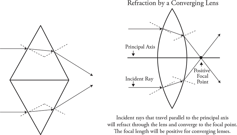
Let’s concentrate only on the rays that transmit through the prism and make some lenses! Place two prisms together flat side to flat side, smooth it out, and shazam poof, you have a converging or convex lens.
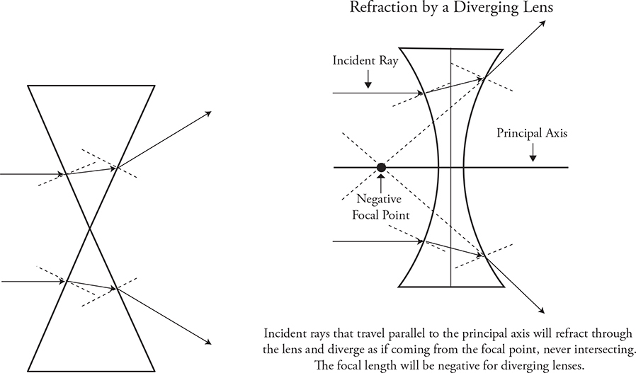
Place two prisms point to point, smooth them out, and you have a diverging or concave lens.
So, lenses work by bending (refracting) light. The shape of the lens is very important, as you can see. Equally important is how much the light changes speed. The more difference there is between the index of refraction of the lens and the air, the greater the bending (refracting). In fact, if you place the lens in a fluid that has the same index of refraction as the lens itself, the lens won’t bend the light at all, because there is no change in velocity as the wave moves from the fluid to the lens. No change in velocity equals no refraction.
Now let’s take a look at what these lenses can do for us.
We’ll start by working with a convex lens. The rules to follow with convex lenses are these:
• An incident ray that is parallel to the principal axis refracts through the far focal point.
• An incident ray that goes through near focal point refracts parallel to the principal axis.
• The lensmaker’s equation and the equation to find magnification, shown below, are the same as for mirrors. In the lensmaker’s equation, f is positive for converging/convex lenses and negative for diverging/concave lenses.
• 
• 
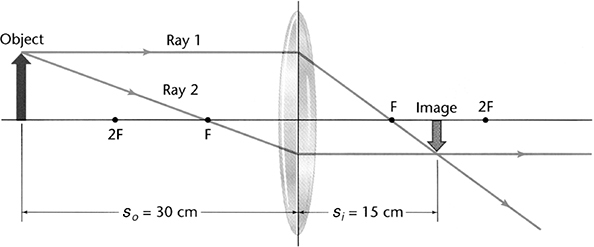
Want to try these rules out? Sure you do. We’ll start, as shown in the next figure, by placing our arrow farther from the lens than the focal point. Notice how the image is inverted, real, and smaller. This means the image distance will be a positive number and the magnification will be less than 1.
We could also demonstrate what would happen if we placed our object in between the near focal point and the lens. But so could you, as long as you follow our rules. And we don’t want to stifle your artistic expression. So go for it.4
Now, how about a numerical problem?
A 3-cm-tall object is placed 20 cm from a converging lens. The focal distance of the lens is 10 cm. How tall will the image be?
We are given so and f. (Note that the focal length is positive for a converging lens.) So we have enough information to solve for si using the lensmaker’s equation.
Solving, we have si = 20 cm. Since the image distance is positive, we know that the image will appear on the far side of the lens as a real/inverted image. Now we can use the magnification equation.
![]()
Our answers tell us that the image is exactly the same size as the object. So our answer is that the image is 3 cm tall, that it is inverted and real.
When working with diverging lenses, follow these rules:
• An incident ray parallel to the principal axis will refract as if it came from the near focal point.
• An incident ray toward the far focal point refracts parallel to the principal axis.
• The lensmaker’s equation and the magnification equation still hold true. With diverging lenses, though, f is negative.
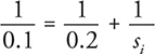
We’ll illustrate these rules by showing what happens when an object is placed farther from a concave lens than the focal point. This is shown in the next figure.
The image is upright, so we know that it is virtual.
Now go off and play with lenses. And spoons. And take out that box of crayons that has been collecting dust in your cupboard and draw a picture. Let your inner artist go wild. (Oh, and do the practice problems, too!)
❯ Practice Problems
Multiple Choice
1. Monochromatic light passing through a double slit produces an interference pattern on a screen a distance 2.0 m away. The third-order maximum is located 1.5 cm away from the central maximum. Which of the following adjustments would cause the third-order maximum instead to be located 3.0 cm from the central maximum?
(A) Moving light source farther from the slits
(B) Decreasing the wavelength of the light
(C) Moving the screen closer to the slits
(D) Decreasing the distance between slits
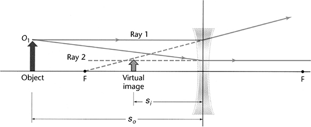
2. Two waves travel through different materials. The graph of the vertical position y of a point in the medium as a function of time t for each wave is shown in the figure. Which of the following statements can be verified using the data presented in the figure?
(A) Wave A has a high frequency than wave B.
(B) Both waves have the same amplitude.
(C) Both waves have the same time period of motion.
(D) The equation of motion for wave B is ![]() .
.
3. An object is placed in front of a spherical convex mirror with a focal length f. Which of the following object distances so will produce an inverted image?
(A) so < f
(B) 2f > so > f
(C) so > 2f
(D) There is not a location so that produces an inverted image.
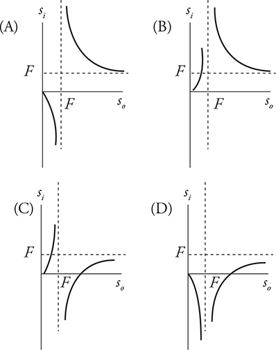
4. Using a convex lens, students take measurements of both the distance of the object from the lens so and the image distance from the lens si and then graph the data. The focal length F is shown each axis. Which of the following figures best depicts the results of the graphed data?
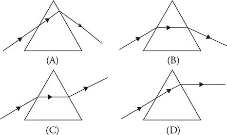
5. Light travels from air into a plastic prism. Which of the following ray diagrams correctly shows the path of the ray that travels through the prism?
6. In an aquarium, light traveling through water (n = 1.3) is incident upon the glass container (n = 1.5) at an angle of 36° from the normal. What is the angle of transmission in the glass?
(A) The light will not enter the glass because of total internal reflection.
(B) 31°
(C) 36°
(D) 41°
7. Light waves traveling through air strike the surface of water at an angle. Which of the following statements about the light’s wave properties upon entering the water is correct?
(A) The light’s speed, frequency, and wavelength all change.
(B) The light’s speed and frequency change, but the wavelength stays the same.
(C) The light’s wavelength and frequency change, but the light’s speed stays the same.
(D) The light’s wavelength and speed change, but the frequency stays the same.
8. An object is placed at the center of curvature of a concave spherical mirror. What kind of image is formed, and where is that image located?
(A) A real image is formed at the focal point of the mirror.
(B) A real image is formed at the center of curvature of the mirror.
(C) A real image is formed one focal length beyond the center of curvature of the mirror.
(D) A virtual image is formed one radius behind the mirror.
9. In a laboratory experiment, you shine a green laser past a strand of hair. This produces a light and dark pattern on a screen. You notice that the lab group next to you has produced a similar pattern on a screen, but the light and dark areas are spread farther apart. Which of the following could cause the light and dark pattern to spread? (Select two answers.)
(A) The second group used thinner hair.
(B) The second group is using a red laser.
(C) The second group had the screen closer to the hair.
(D) The second group held the laser farther from the hair.
10. In a human eye, the distance from the lens to the retina, on which the image is focused, is 20 mm. A book is held 30 cm from the eye, and the focal length of the eye is 16 mm. How far from the retina does the image form, and what lens should be used to place the image directly on the retina?

Free Response
11. Laser light is passed through a diffraction grating with 7000 lines per centimeter. Light is projected onto a screen far away. An observer by the diffraction grating observes the first-order maximum 25° away from the central maximum.
(A) What is the wavelength of the laser?
(B) If the first-order maximum is 40 cm away from the central maximum on the screen, how far away is the screen from the diffraction grating?
(C) How far, measured along the screen, from the central maximum will the second-order maximum be?
12. Your eye has a lens that forms an image on the retina.
(A) What kind of lens does your eye have? Justify your answer.
(B) You develop an eye disorder where your eye forms the image in front of your retina. What kind of corrective lens is needed so that you can see clearly? Justify your answer.
13. Which of the following optical instruments can produce a virtual image with magnification 0.5? Justify your answer.
(A) Convex mirror
(B) Concave mirror
(C) Convex lens
(D) Concave lens
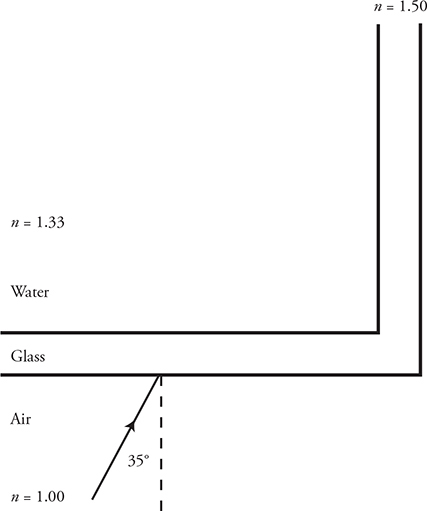
14. Light traveling through air encounters a glass aquarium filled with water. The light is incident on the glass from the front at an angle of 35°.
(A) At what angle does the light enter the glass?
(B) At what angle does the light enter the water?
(C) On the diagram above, sketch the path of the light as it travels from air to water. Include all reflected and refracted rays; label all angles of reflection and refraction.
After entering the water, the light encounters the side of the aquarium, hence traveling back from water to glass. The side of the tank is perpendicular to the front.
(D) At what angle does light enter the glass on the side of the aquarium?
(E) Does the light travel out of the glass and into the air, or does total internal reflection occur? Justify your answer.
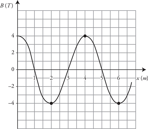
15. (A) Write the appropriate wave equation for the following electromagnetic wave representation.
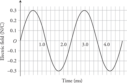
(B) Produce a sketch of this wave equation on the axis:  , where B is in units of T, and x is in units of m.
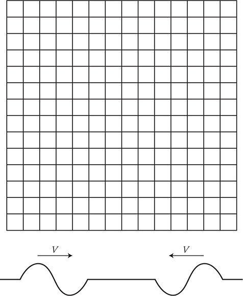
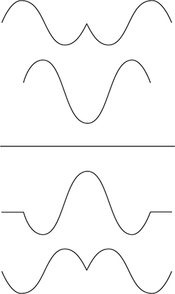
16. Two waves travel toward each other, as shown in the figure. Sketch at least three unique interference patterns that will be seen as the waves pass each other.
17. Use the point source model of wave propagation to describe and explain the behaviors of the waves listed here. Sketch a representation to assist in your explanation.
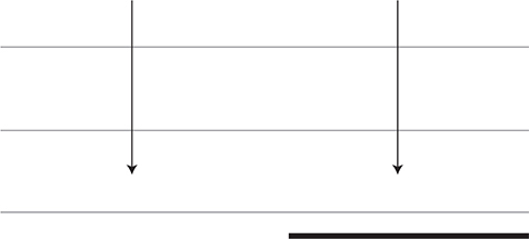
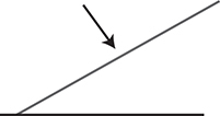
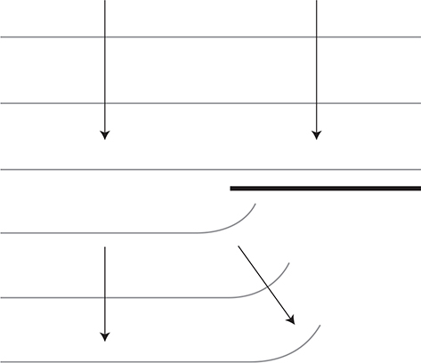
(A) Diffraction of a plane wave front as it passes by a boundary (see figure).
(B) Sound waves can be heard around corners, but light waves do not seem to bend around corners. Why is this?
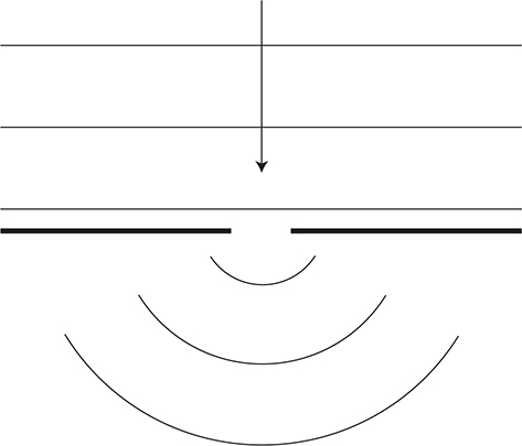
(C) Diffraction of a plane wave front as it passes through a small opening comparable in size to the wavelength (see figure).

(D) Diffraction of a plane wave front as it passes through an opening that is larger than the wavelength (see figure).

(E) Double-slit interference pattern that appears when a plane wave front passes through two small openings (see figure).

(F) Refraction of light as light passes from air straight into a block of glass (see figure). Which way will the light turn and why?
(G) Refraction of light as light passes at an angle from a faster speed medium into a slower speed medium (see figure). Which way will the light turn and why?
(H) A plane wave front of light reflecting off a flat mirror (see figure).
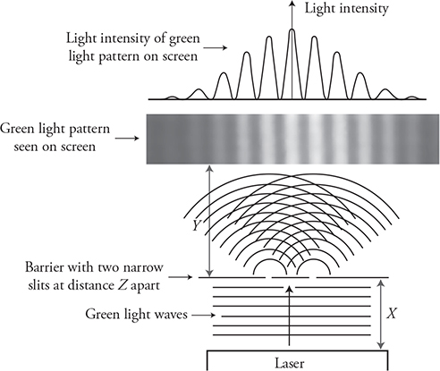
18. Green laser light waves are projected toward a barrier with two narrow slits of width W separated by a distance of Z. This produces an alternating light-dark pattern on a screen, as shown in the figure. The barrier is a distance of Y from the screen. The laser light source is a distance of X from the slit barrier. For each of the following modifications to the apparatus, describe the changes that will be observed in the light pattern seen on the screen, and sketch the new pattern. Justify each claim with an equation.
(A) Decrease W.
(B) Decrease X.
(C) Decrease Y.
(D) Decrease Z.
(E) Use a red laser instead of a green one.
(F) Use a violet laser instead of a green one.
(G) Replace the double-slit barrier with a multi-slit diffraction grating with the same slit spacing of Z.
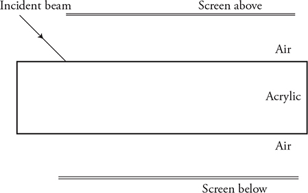
19. Students shine a laser beam at a rectangular block of acrylic plastic, as shown in the figure. Two dots of light appear on a screen above the acrylic block, one to the right and one to the left. Likewise, two dots of light appear below the block, one to the right and one to the left.
(A) Sketch a ray diagram that could produce such an arrangement of light dots. In your diagram, indicate which angles measured between the light ray and the normal line.
(B) Which of the dots (right or left) is brighter than the other on the screen both above and below the acrylic block? Explain your reasoning.
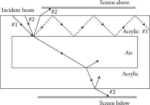
The original acrylic block is replaced by a new block with a rectangular air gap in the middle, as shown in the figure.
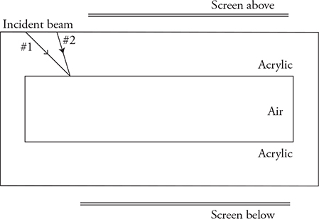
(C) A laser beam positioned at #1 does not produce a dot on the top or bottom screen. Explain why this is, and draw a ray diagram to support your claim.
(D) When positioned at #2, the laser produces a dot of light on both screens. Explain why this happens, and draw a ray diagram to support your claim.
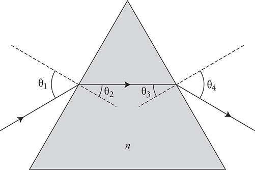
20. Your physics teacher instructs you to determine the index of refraction of a triangular glass prism.
(A) List the items you would use to perform this investigation.
(B) Sketch a simple diagram of your investigation. Make sure to label all items, and label the measurements you would make.
(C) Outline the experimental procedure you would use to gather the necessary data. Indicate the measurements to be taken and how the measurements will be used to obtain the data needed. Make sure your outline contains sufficient detail so that another student could follow your procedure and duplicate your results.
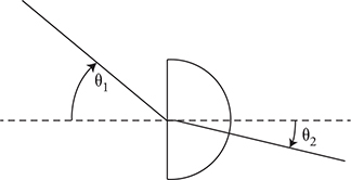
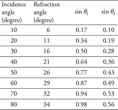
21. A group of students are given a semicircular sapphire prism through which they shine a beam of light, as shown in the figure. They measure the incident and refracted angle of the light and produce the table shown.
(A) Use the data to determine the index of refraction of the prism.
(B) Graph the refraction angle as a function of incidence angle. Are the two variables directly related? Justify your claim.
(C) Graph the sine of the refraction angle as a function of the sine of the incidence angle. Use the slope of the graph to calculate the index of refraction of the prism. Show your work.
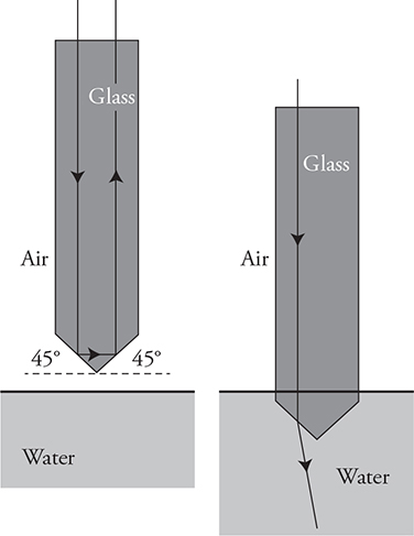
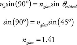
22. A glass prism has a point at the bottom made up of 45° angled surfaces, as shown in the figure. A light beam directed downward through the top of the prism is completely reflected off the bottom surfaces and exits back through the top of the prism. When submerged in water, the light beam exits the bottom of the prism.
(A) Calculate the minimum index of refraction of the glass.
(B) In a clear, coherent, paragraph-length response, explain why light exits the bottom of the prism when it is submerged in water. Your explanation should discuss the speed of light.
23. An object is placed in front of each of the lenses/mirrors shown in each figure below.
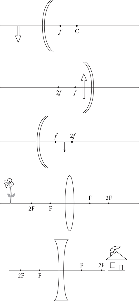
(A) Sketch a ray diagram with at least two rays to locate the position of the image. Sketch the image.
(B) Next to each image, indicate whether the image is real or virtual, inverted or upright, and enlarged or reduced in size.
(C) Sketch a stick figure on each diagram to indicate where a person would have to be standing and in which direction the person needs to look to see the image formed by the mirror.
(D) What distinguishes a real image from a virtual image in these ray diagrams? Explain.
(E) What would happen to the image of the flower if the bottom half of the lens were covered by a piece of cardboard? Justify your claim by making reference to the ray diagram.
24. Your physics teacher instructs you to determine the focal length of a concave mirror.
(A) List the items you would use to perform this investigation.
(B) Sketch a simple diagram of your investigation. Make sure to label all items, and indicate measurements you would need to make.
(C) Outline the experimental procedure you would use to gather the necessary data. Indicate the measurements to be taken and how the measurements will be used to obtain the data needed. Make sure your outline contains sufficient detail so that another student could follow your procedure and duplicate your results.
(D) Could this procedure be used to find the focal length of a convex mirror? Justify your response.
25. A lens lab produces these data and the graph.
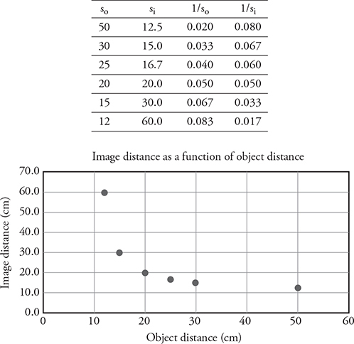
(A) What data would you plot to produce a straight line? Plot the data.
(B) What information from your straight line plot will allow you to determine the focal length of the lens? Justify your claim with an equation. Calculate the focal length of the lens using your straight line graph.
❯ Solutions to Practice Problems
1. (D) Using the equation, d sin θ = mλ, we want to increase θ while keeping m = 3. We could do this by decreasing d or increasing λ. Or we could keep θ the same but just move the slits farther from the screen, which will enlarge the pattern by spreading it out with added distance. Moving the light source farther from the slits won’t change anything.
2. (D) The two waves do not have the same time period. Wave B has a higher frequency. Wave A has an amplitude of only 15 cm. The equation for a wave is x = A sin (2πft). Wave B has an amplitude of 30 cm and a time period of 0.08 seconds and, therefore, a frequency of 1/0.08 Hz.
3. (D) A convex/diverging mirror produces only virtual/upright images of reduced size.
4. (A) Convex lenses produce real images (positive si) when the object distance is beyond the focal point, and virtual images (negative si) when the object distance is inside the focal length.
5. (B) A and D do not refract the light correctly at the first surface. Light should be bending toward the normal as it is slowing down. Exiting the prism, light will speed back up and should bend away from the normal. So C is right out. That leaves answer choice B.
6. (B) If you had a calculator, you could use Snell’s law, calling the water medium “1” and the glass medium “2”: 1.3 sin 36° = 1.5 sin θ2. You would find that the angle of transmission is 31°. But, you don’t need a calculator . . . so look at the choices. The light must bend toward the normal when traveling into a material with higher index of refraction, and choice B is the only angle smaller than the angle of incidence. Choice A is silly because total internal reflection can occur only when light goes from high to low index of refraction.
7. (D) The speed of light (or any wave) depends upon the material through which the wave travels; by moving into the water, the light’s speed slows down. But the frequency of a wave does not change, even when the wave changes material. This is why tree leaves still look green under water—color is determined by frequency, and the frequency of light under water is the same as in air. So, if speed changes and frequency stays the same, by v = λf, the wavelength must also change.
8. (B) You could approximate the answer by making a ray diagram, but the mirror equation works, too:

Because the radius of a spherical mirror is twice the focal length, and we have placed the object at the center of curvature, the object distance is equal to 2f. Solve the mirror equation for si by finding a common denominator:

9. (A) and (B) 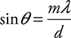 . Increasing the wavelength of the laser (λ) and/or decreasing the hair width (d) will both increase the angle of the pattern.
10. (A) Be careful of units! Convert the object distance from 30 cm to 300 mm.
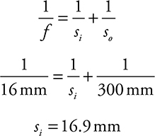
This means the image is 3.1 mm in front of the retina, which is at a distance of 20 mm. We need a diverging lens to move the image back to the retina. Diverging lenses are concave.
11. (A) Use d sin θ = mλ. Here d is not 7000! d represents the distance between slits. Because there are 7000 lines per centimeter, there’s 1/7000 centimeter per line; thus, the distance between lines is 1.4 × 10⁻⁴ cm, or 1.4 × 10⁻⁶ m. θ is 25° for the first-order maximum, where m = 1. Plugging in, you get a wavelength of just about 6 × 10⁻⁷ m, also known as 600 nm.
(B) This is a geometry problem.
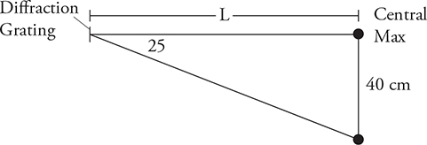
tan 25° = (40 cm)/L; solve for L to get 86 cm.
(C) Use d sin θ = mλ; solve for θ using m = 2, and convert everything to meters. We get sin θ = 2(6.0 × 10⁻⁷ m)/(1.4 × 10−6 m). The angle will be 59°. Now, use the same geometry from part (b) to find the distance along the screen: tan 59° = x/(0.86 m), so x = 143 cm. (Your answer will be counted correct if you rounded differently and just came close to 143 cm.)
12. (A) Converging—Convex lens. This type of lens will form a real image that can be projected on a screen (retina). Note that the image will be upside down. Your brain flips the image over!
(B) The light rays are converging too soon. We need the rays to converge farther from the eye lens. This requires a diverging—concave lens that will spread the light out a bit before it enters the eye. The eye will then focus the light on the retina.
13. (A and D) The converging optical instruments—convex lens and concave mirror—only produce virtual images if the object is inside the focal point. But when that happens, the virtual image is larger than the object, as when you look at yourself in a shaving mirror. But diverging optical instruments—a convex mirror and a concave lens—always produce a smaller, upright image, as when you look at yourself reflected in a Christmas tree ornament.
14. (A) Use Snell’s law: n1 sin θ1 = n2 sin θ2. This becomes 1.0 sin 35° = 1.5 sin θ2. Solve for θ2 to get 22°.
(B) Use Snell’s law again. This time, the angle of incidence on the water is equal to the angle of refraction in the glass, or 22°. The angle of refraction in water is 25°. This makes sense because light should bend away from normal when entering the water, because water has smaller index of refraction than glass.
(C) Important points:
• Light both refracts and reflects at both surfaces. You must show the reflection, with the angle of incidence equal to the angle of reflection.
• We know you don’t have a protractor, so the angles don’t have to be perfect. But the light must bend toward normal when entering glass, and away from normal when entering water. If you have trouble drawing this on the AP exam, just explain your drawing with a quick note to clarify it for the exam reader. This helps you and the reader!

(D) The angle of incidence on the side must be measured from the normal. The angle of incidence is not 25°, then, but 90 − 25 = 65°. Using Snell’s law, 1.33 sin 65° = 1.50 sin θ2. The angle of refraction is 53°.
(E) The critical angle for glass to air is given by sin θc = 1.0/1.5. So θc = 42°. Because the angle of incidence from the glass is 53° [calculated in (D)], total internal reflection occurs.
15. (A) 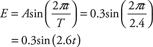
(B) 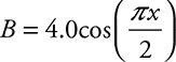 . This is a cosine wave with an amplitude of 4.0 T and wavelength of 4 m.
16. Here are six of the interference patterns seen as the two waves first touch, partially overlap, completely overlap, and then pass by each other.
17. (A) The portion of the wave that hits the boundary on the right side will be reflected or absorbed. The left half of the wave will pass by the boundary. The wavelets that are produced at the edge of the boundary will cause the wave to curve around the edge of the boundary.
(B) Sound waves have a long wavelength that produces large wavelets near the boundary causing a pronounced diffraction effect of “bending around the corner.” As the wavelength gets smaller than the boundary itself, as in visible light waves, the diffraction effect is less pronounced because the wavelets near the boundary are small and produce only a small bending effect around the corner near the edge of the wave front.
(C) The point source model shows that when the opening is comparable in size to the wavelength, there will be a pronounced diffraction (bending of the wave front) around the corners of the opening.
(D) When the opening is much larger than the wavelength, the point source model shows that only the edges of the wave show any bending or diffraction. The wavelets in the center overlap and continue the propagation of the plane wave unchanged.
(E) The point source model shows that the two slits will produce two separate curved wave fronts passing through the openings. These two new wave fronts will interfere with each other, creating a pattern of constructive and destructive interference.
(F) The speed of light in the new medium is slower. Drawing the Huygens’ wavelets, we can see that all parts of the wave will slow down at the same time. This means the wave front will not change direction but will simply travel straight through the glass with a shorter wavelength.
(G) Entering the new medium, the wave slows down. Drawing the wavelets in the new medium with a shorter wavelength, we see that the wave front changes direction, and the wave ray bends toward the normal line to the surface.
(H) Drawing wavelets for the wave that reflects off the surface, we see that the wave maintains the same speed and wavelength. However, the reflected wave front turns and travel off in a new direction. The angle of the incoming wave front measured to the normal is equal to the angle of the outbound reflected wave front measured to the normal line.
18. The light and dark pattern of double-slit diffraction is described by the equation d sin θ = mλ, where d is the distance between the two slits; θ is the wavelength of the light; λ is the angle from the slit to the maxima (bright spot) on the screen; and m is the maxima number. Note that m = 0 is the central maxima right down the center along the line of symmetry, and m = 1 would be the first maxima to either side of the central maxima. Solving the equation for our situation, we get 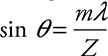 . Therefore, as λ goes up or Z goes down, θ increases.
(A) As W decreases, there will be no change to the pattern. Nothing in the equation changes. Note: Remember that the slit opening width and the wavelength of the green light need to be approximately the same size (order of magnitude) to produce diffraction effects.
(B) As X decreases, there will be no change to the pattern because nothing in the equation changes.
(C) As Y decreases, nothing in the equation changes. However, since the screen is closer to the barrier, there is less distance/time for the pattern to spread out before it hits the screen. Therefore, the pattern will become closer together and more tightly packed.
(D) As Z decreases, θ increases. Therefore, the pattern becomes wider and more spread out.
(E) Red light has a longer wavelength, which will increase θ, making the pattern spread out.
(F) Violet light has a shorter wavelength, which will decrease θ, making the pattern narrower.
(G) The maximas will be in the same locations but will be thinner, more point like.
19. (A)
(B) The dots on the left are brighter both above and below the acrylic block. Conservation of energy tells us that less and less of the light is making it through to the right dots. At each medium interface, some of the light is reflected leaving less light energy to continue on into the next medium.
(C) Ray #1 must be striking the acrylic/air interface at an angle of incidence larger than the critical angle. This produces total internal reflection along the parallel top and bottom surfaces, as shown by the dashed line in the figure.
(D) Ray #2 must be striking the acrylic/air interface at an angle less than the critical angle. There is a partial reflection and refraction at each surface. This will produce a dot on each screen, as shown by a solid line in the figure.
20. (A) Equipment: protractor, pencil, ruler, sheet of white paper
(B) See figure.
(C) Procedure:
1. Place the prism in the center of the sheet of paper.
2. Trace the outside of the prism with the pencil.
3. Direct the laser beam so it passes through the prism.
4. Trace the ray’s path with the ruler before it enters the prism and after it exits, being sure to mark the entrance and exit locations.
5. Remove the prism. Mark the normal line at the incoming and outgoing surfaces. Now that the prism is removed and the entrance and exit points for the light beam are marked, trace the light ray’s path through the prism.
6. Using the protractor, measure the angles of incidence and refraction for each incoming and outgoing ray.
7. Use Snell’s law to calculate the index of refraction of the glass prism.
8. To reduce error, repeat for a wide variety of angles, and average the result.
21. (A) Use Snell’s law and the first set of data:
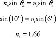
Repeating this for the rest of the data in the table, we get an average of 1.76.
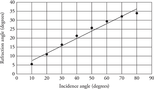
(B) We can see in the figure that the trend line does not match the data and clearly shows the data are not straight and cannot be a direct relationship.
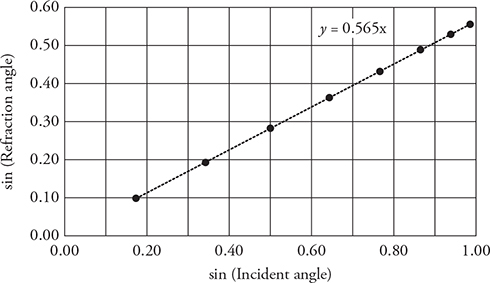
(C) Plotting the sine of the refracted angle as a function of the sine of the incident angle produces a straight line. This makes sense:
Matching Snell’s law up to the equation of a line we can see that the slope of the line is equal to the reciprocal of the index of refraction of the sapphire. The best fit line gives a slope of 0.565. Thus, ns = 1.77.
22. (A) Remember that at the critical angle, the refracted angle is 90°. Calculating the minimum index of refraction so light does not escape at a critical angle of 45 degrees is shown by the following calculation:
(B) Originally, the light is traveling in glass and is trying to exit out into air and the light strikes the bottom of the prism beyond the critical angle. When the prism is lowered into water, the difference in the index of refraction between the glass and water is less than between the glass and air. Therefore, the light does not speed up as much going into the water as it did going into air. This reduces the bending of the light due to refraction. The light is no longer hitting the bottom of the prism beyond the critical angle. Therefore, the light is able to escape out the bottom of the prism into the water but was not able to escape into the air.
23. (A) See figure.
(B) See figure.
(C) See figure.
(D) Light rays converge to form real images. Light rays diverge from the location of a virtual image as if they came from that spot, even though they did not actually pass through that location.
(E) Since half of the light rays will still be passing through the lens unimpeded, the image will still form in the same spot with the same properties as before. However, the image will not be as bright because half of the rays from the flower are now blocked.
24. There are several ways to perform this lab. Here is one method.
(A) Equipment: mirror, meter stick, candle, screen
(B) See figure.
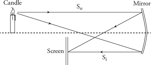
(C) Procedure:
1. Place the mirror, candle, and screen on a table, as shown in the figure.
2. Move the screen until a crisp image forms.
3. Measure the object distance from the mirror to the candle and the image distance from the mirror to the screen.
4. Repeat this process for several data points.
5. Graphing ![]() on the x-axis and
on the x-axis and ![]() on the y-axis, we should get a graph with a slope of −1 and an intercept that equals
on the y-axis, we should get a graph with a slope of −1 and an intercept that equals ![]() . (You can also use the mirror equation to calculate the focal length for each set of data and average, but the AP test usually asks you to graph a straight line graph to find what you are looking for.)
. (You can also use the mirror equation to calculate the focal length for each set of data and average, but the AP test usually asks you to graph a straight line graph to find what you are looking for.)
(D) No! A convex mirror will not produce a real image on the screen.
25. (A) Graph ![]() on the x-axis and
on the x-axis and ![]() on the y-axis, we should get a graph with a straight line with a slope of −1.
on the y-axis, we should get a graph with a straight line with a slope of −1.
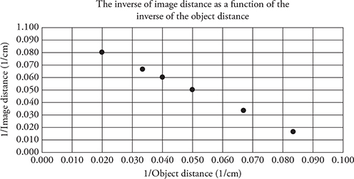
(B) Rearranging the lens equation and comparing it to the equation of a line, we can see that the intercept of the line equals ![]() .
.
The intercept equals 0.1 (1/cm). Therefore, the focal length is 10 cm.
❯ Rapid Review
• Waves can be either transverse or longitudinal. Transverse waves are up—down waves, like a sine curve. Longitudinal waves are push—pull waves, like a sound wave traveling through the air.
• When two waves cross paths, they can interfere either constructively or destructively. Constructive interference means that the peaks, or troughs, of the waves line up, so when the waves come together, they combine to make a wave with bigger amplitude than either individual wave. Destructive interference means that the peak of one wave lines up with the trough of the other, so when the waves come together, they produce a smaller amplitude. Once the waves pass through each other, the interference pattern stops and the waves revert back to their original shapes.
• All electromagnetic waves travel at a speed of 3 × 10⁸ m/s in a vacuum.
• The double-slit experiment demonstrates that light behaves like a wave.
• When light travels through anything other than a vacuum, it slows down, and its wavelength decreases. The amount by which light slows down as it passes through a medium (such as air or water) is related to that medium’s index of refraction.
• Thin films can cause constructive or destructive interference, depending on the thickness of the film and the wavelength of the light. When solving problems with thin films, remember to watch out for phase changes.
• Light: radio waves, microwaves, infrared, visible, ultraviolet, X-rays, and gamma rays, are all electromagnetic waves. EM waves are transverse and can be polarized.
• Diffraction (the bending of waves around obstacles), interference (constructive/destructive addition of intensity), and refraction (the bending of light when it changes speed) are wave properties of light. These properties can be explained using the point source model of waves.
• When light encounters a new medium, it can reflect, transmit (refract), or be absorbed. All three can happen at the same time. Remember that energy is conserved! If 60% of the wave energy reflects at a surface and 30% of the wave energy refracts, 10% of the wave energy must have been absorbed.
• Snell’s law describes how the direction of a light beam changes as it goes from a material with one index of refraction to a material with a different index of refraction.
• When light is directed at or beyond the critical angle, it cannot pass from a material with a high index of refraction to one with a low index of refraction; instead, it undergoes total internal reflection.
• When solving a problem involving a plane mirror, remember (1) the image is upright (it is a virtual image); (2) the magnification equals 1; and (3) the image distance equals the object distance.
• When solving a problem involving a spherical mirror, remember (1) incident rays parallel to the principal axis reflect through the focal point; (2) incident rays going through the focal point reflect parallel to the principal axis; (3) points on the same side of the mirror as the object are a positive distance from the mirror, and points on the other side are a negative distance from the mirror; (4) the lensmaker’s equation (also called the mirror equation in this case) holds; and (5) concave mirrors have a positive focal length, while convex mirrors have a negative focal length.
• When solving problems involving a convex lens, remember (1) incident rays parallel to the principal axis refract through the far focal point; (2) incident rays going through the near focal point refract parallel to the principal axis; and (3) the lensmaker’s equation holds, and f is positive.
• When solving problems involving a concave lens, remember (1) incident rays parallel to the principal axis refract as if they came from the near focal point; (2) incident rays going toward the far focal point refract parallel to the principal axis; and (3) the lensmaker’s equation holds with a negative f.
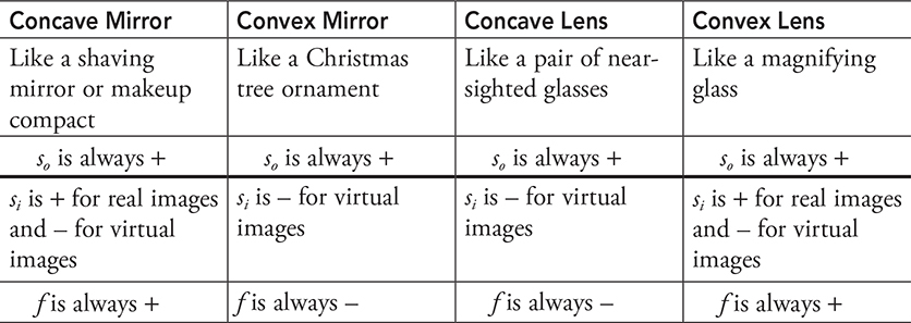
Summary of Signs for Mirrors and Lenses
1The “incident” angle simply means “the angle that the initial ray happened to make.”
2TRY THIS! Light a candle; reflect the candle in a concave mirror; and put a piece of paper where the image forms. . . . You will actually see a picture of the upside-down, flickering candle!
3Remember that in physics, “normal” means “perpendicular”—the normal is always perpendicular to a surface.
4Answer: The image is a virtual image, located on the same side of the lens as the object, but farther from the lens than the object. This means that the image distance will be a negative number and the magnification will be greater than 1.