Make: The Annotated Build-It-Yourself Science Laboratory (2015)
Part II. Physics
Chapter 4. Electricity and Magnetism
Making a Magnet (or Recharging a Magnet)
Purpose: If you learn how to make magnets you will not only be able to make magnets without cost, but you will learn something about the nature of magnetism.
Materials: Strong bar magnet1 and some things made of iron, steel, brass, pot metal, copper, and other metals.
What to Do: Stroke the object to be magnetized with a bar magnet. Try to imagine the object to be magnetized as being made up of many small compasses. You want to line up all the compasses so the needles point in the same direction. You will need to stroke the object many times.
Can You Work Like a Scientist?
1. If you rub the object back and forth with a magnet, does it magnetize very well? Check with a magnetometer (see “Magnetometer”).
2. Try rubbing the object in only one direction. Is the result better?
3. Check your magnet with a compass. Does it have one or two poles? Can you explain this on the basis that the object is made up of small materials that act like compasses?
4. Rub two objects the same way with a magnet. Check the poles with a compass. Are the poles alike or different? Do the same poles of the objects push away (repel) or draw together (attract) each other?
5. Which materials magnetize the easiest? Which materials keep their magnetism the longest?
6. Can you make a magnet by placing it in a north and south position and leaving it? Try this for several days. Why might or might not this work?
7. Can you place an object in a north and south position and magnetize it by hitting it with a hammer?
8. Check cans in a store to see if any are magnetized.
9. Are cans just made of tin?
10.Will a magnet pick up a nickel? Try a Canadian nickel too.
11.Can you make a magnet out of a nail by holding a strong magnet nearby?
12.Will magnetism go through things? Try glass, paper, books, table tops, other metals, etc.
13.Set a thin box on top of your magnet. Shake in some iron filings. If you don’t have any, use a file on a nail. Tap the box. Do you see the lines of force? What part of the magnet is the strongest?
14.How can you destroy your magnet? Can you think of five ways?
Magnetometer
Purpose: This instrument is used for measuring the strength of magnets, either permanent or electric magnets.
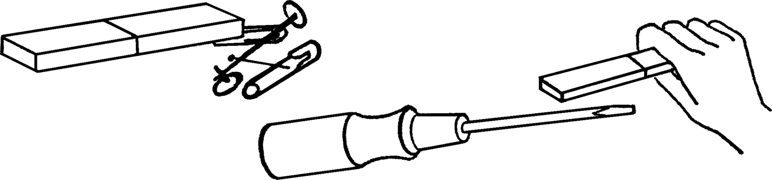
Materials: Ruler or yardstick, rubber band that will stretch easily, thumbtack, and a paper clip.
What to Do: Stick a thumbtack in the ruler or yardstick near the end. Break the rubber band and tie one end around the tack. Tie the other end to a paper clip.
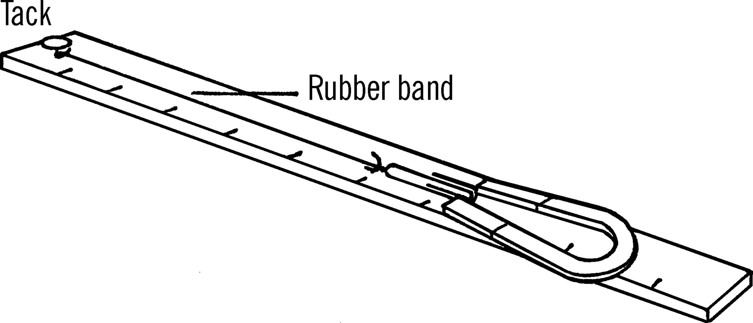
Operation of Equipment: Hold the ruler or yardstick with one hand. Bring the magnet to be tested near the end of the paper clip. Pull the paper clip with the magnet slowly. The rubber band will stretch to a point where the strength of the magnet is equal to the pull of the rubber band. At that point, the paper clip will break loose from the magnet. Note the number on the ruler that the paper clip reaches. This number will tell you the strength of the magnet compared with other magnets.
Can You Work Like a Scientist?
1. How can you make your magnetometer more sensitive?
2. Keep a chart of how many times you rub a screwdriver with a magnet and the strength the magnet has each time. What do you conclude from this?
3. Do both poles of a magnet have the same strength?
4. Try magnetizing different materials in the same way. Which material is magnetized the most? Which the least?
5. Try putting two bar magnets together end to end. Is the magnet stronger?
6. What part of the magnet is the strongest-the end or the middle?
7. What materials hold their magnetism the longest? Keep a graph on the time and the strength of each material.
8. Make an electromagnet out of a coil of wire. Connect it to a battery. How strong is the magnetism around the wire?
Now place a nail in the coil. How strong is the electromagnet? Turn off the current. How strong is it now?
9. Magnetize a screwdriver by rubbing it. Measure the strength. Now hit the screwdriver against a table several times. Measure the strength. Can you make the screwdriver non-magnetic?
10.What effect does heat have on a magnet?
11.If you wrap more wire on your coil, will the magnetism increase? Keep a graph of the turns and the strength.
12.Connect more batteries together. Does it make the electromagnet stronger? Can you measure the strength of batteries with this?
Needle Compass
Purpose: To make a sensitive compass out of simple materials in order to demonstrate the law about magnetic poles.
Materials: Two needles, piece of 3” × 5” file card, and a pin.
What to Do: Magnetize the two needles either with your solenoid (see “Solenoid”) or magnet. Check the poles with a compass. Be sure the north poles of both needles point in the same direction. Bend a piece of file card and stick the needles in as shown. Next put the pin through the rest of the cardboard. Balance the compass needles on the point of the pin.
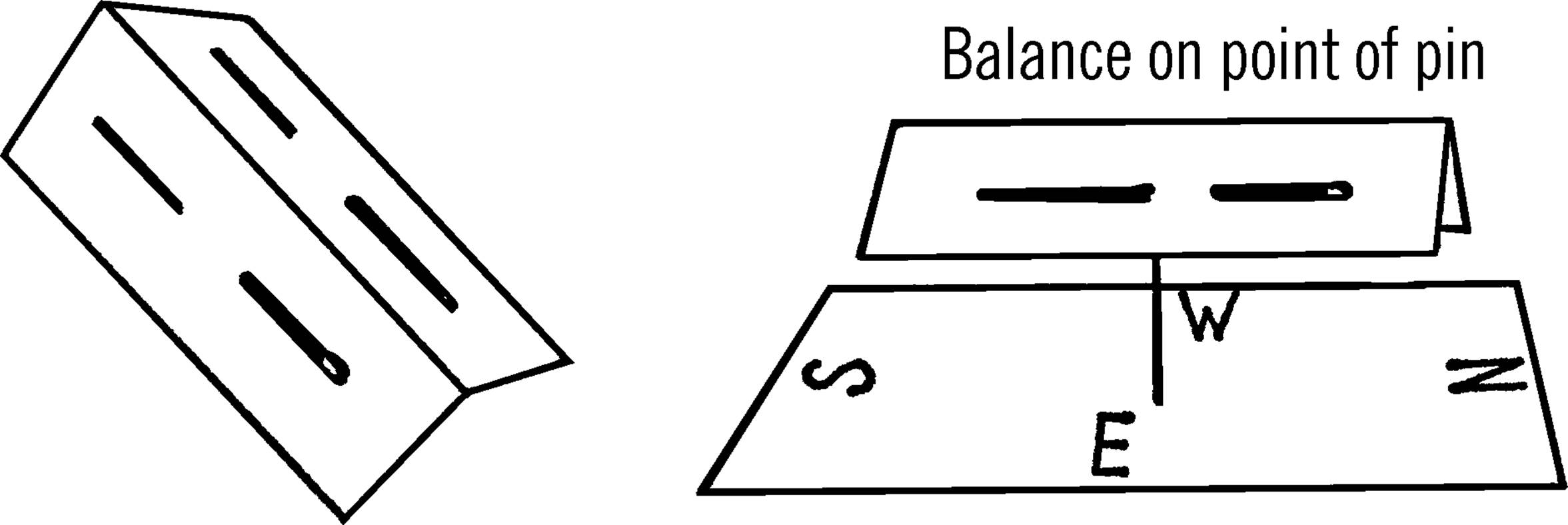
Operation of the Compass: The compass should line up in a north and south direction. Check with your compass. Mark which pole is north and which pole is south.
Can You Work Like a Scientist?
1. Take a magnet. Find its north pole by checking with a compass. Now try your north pole on the north pole of your needle compass. Do they attract or push away (repel)?
2. Try the south pole of the magnet on the south pole of your compass. Do they attract or repel?
3. Now try a north pole on a south pole. Then a south pole on a north pole.
4. Do the same poles attract or repel? Do opposite poles attract or repel?
5. Place some metal nearby to make your needle compass give the wrong reading. Can you correct this by using more metal? Where would you place it? Would this work on a ship?
6. If you were at the North Pole, what direction would be north? What direction would be south?
7. If the Earth acts as a magnet, what must the inside of the Earth be made of?
8. Would a compass work on the moon? How about the other planets?
9. Could you use a compass to locate a meteorite?
10.How far away from your needle compass can you move your magnet and yet affect the compass? Is this distance the same for all magnets?
11.Could you develop a scale for measuring the strength of magnets by using the principle mentioned in question 10?
12.Use your compass to check the polarity (poles) of your refrigerator. Move the compass up and down the outside of the refrigerator.
Watch Spring Compass
Purpose: To detect the North and South Magnetic Poles of the Earth.
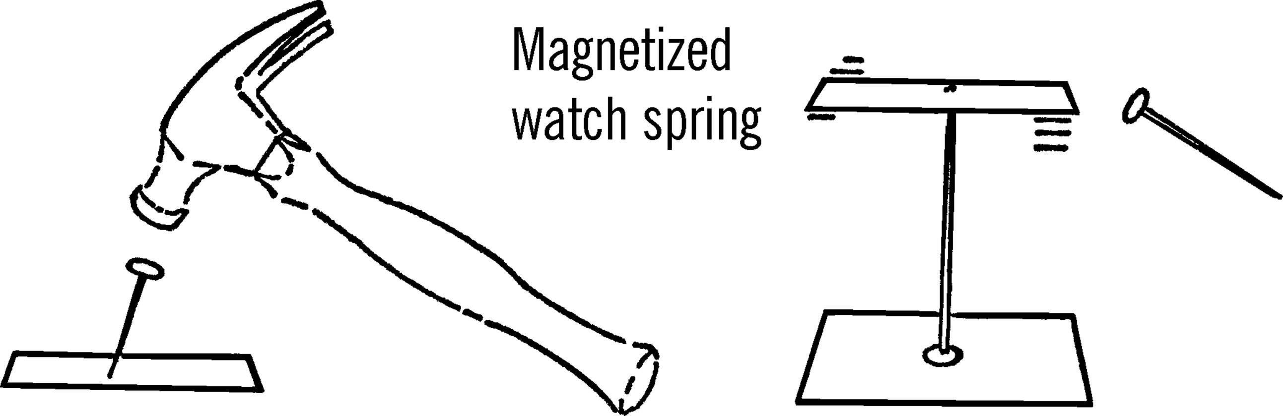
Material: Hard steel, preferably the spring out of an old watch.2
What to Do: Cut the spring so that it is about an inch and a half long. Using a nail or nail punch and a hammer, try to dent the spring near the middle. Now put a pin through a piece of cardboard and balance the watch spring on the point of the pin. Check with a piece of iron to see if the spring acts as a compass.
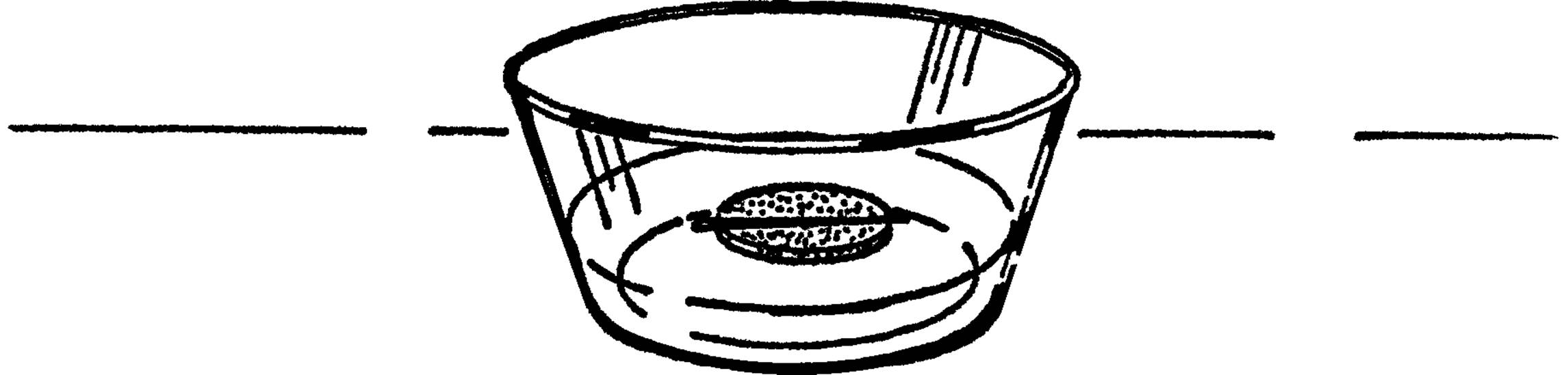
Columbus Compass
Purpose: To show the type of compass Columbus used.
Materials: Needle, cork, and glass dish.
What to Do: Magnetize the needle. Slice a thin section of cork with a razor blade. Lay the needle on the cork or stick the needle through the center. Place the cork in a dish of water.
Can You Work Like a Scientist?
1. Columbus had trouble with his men. As he sailed west, the compass needle didn’t point in the same direction as it did before. Can you show why that would be true by using a globe?
2. Could you use a compass to help you tell longitude?
3. Why didn’t you use a metal pie dish? What might act like a metal pie dish on a boat?
4. How do boats and planes protect themselves from metal?
5. What kinds of compasses do ships use now in place of Columbus’s compass?
Iron Filings
Purpose: Iron filings are used to detect the magnetic lines of force around a magnet or around a wire conducting electricity.
Materials: Soft nail, file, salt or white sand, small box, and plastic sheet or Saran Wrap.
What to Do: You can make your own iron filings by filing a nail. Magnetite is a very cheap substitute for iron filings. In either case, mix the filings with about one fourth salt or white sand. The white sand is the same kind that is used in hotel containers.3 Most hotels would give you a small amount. Place the mixture in a shallow flat box and cover the box with a plastic sheet or a glass plate.
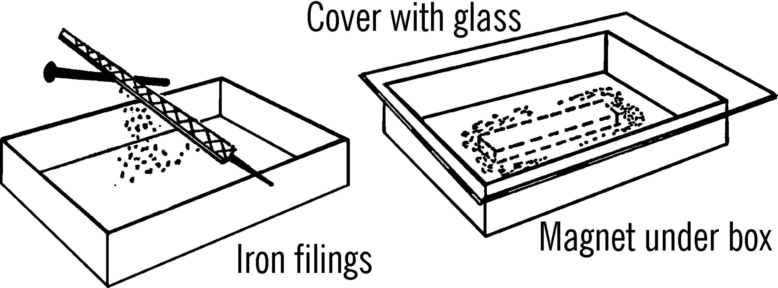
Operation of Equipment: Hold a magnet under the box. Tap the box gently. You should be able to see the magnetic lines of force clearly. The sand or salt outlines the iron filings and makes the lines show up more clearly. If you get filings on your magnet, you can remove the filings with Scotch tape.
Can You Work Like a Scientist?
1. Can you remove the iron filings from the salt or sand mixture? Can you use an electromagnet to do the same thing? Be sure to have a sheet of paper between the filings and the magnet.
2. Does an electromagnet have the same kind of lines of force as a permanent magnet?
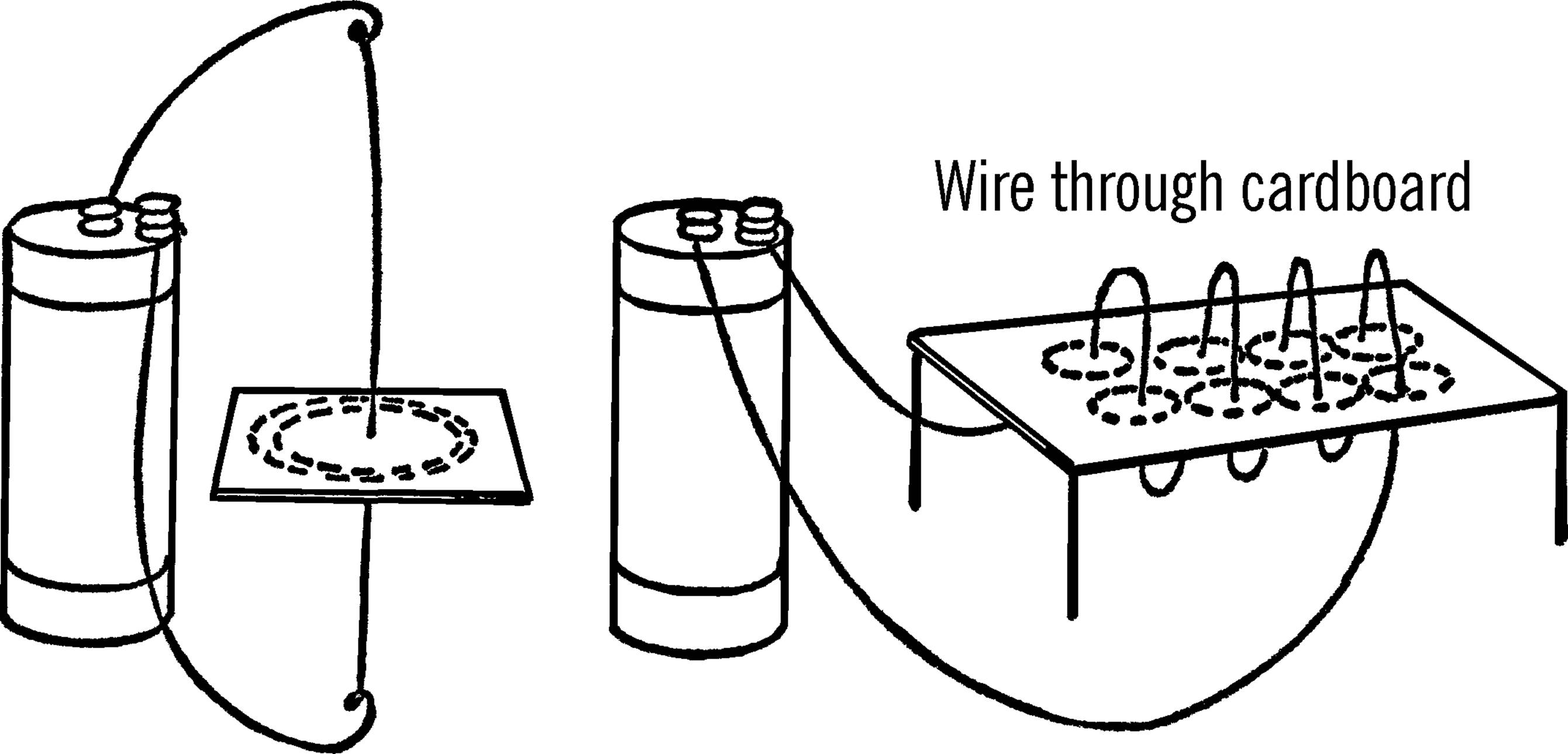
3. Run a wire through a card as shown below. Sprinkle the mixture on the card and connect the wire up to a strong source of direct current. Is there a pattern of magnetic lines of force?
4. Wrap a coil of wire through a card as shown. Connect this up to a source of current.4 Can you see magnetic lines of force?
5. Try this with alternating current.
6. Can you make permanent pictures of magnetic lines of force by forming a pattern of a magnetic field on wax paper and then heating the paper over a strong light bulb?
7. Do filings cling to a bare wire carrying electricity?
8. Can you make Scotch tape magnetic by using iron filings?
Electroscope
Purpose: The purpose of an electroscope is to detect charges of static electricity and to tell the type of charge present.
Materials: Bottle or clear light bulb, a cork or one-hole stopper, heavy copper wire (size 6, 8, or 10), and two short pieces of tape recorder tape.5 In place of the tape you could use gold foil or very thin tinfoil. However, tape recorder tape is light and does an excellent job.
What to Do: If you use a light bulb, use a #1 stopper. If you use a bottle, you can use either a stopper or a cork. Remove the rubber insulation from the wire except for the short section that fits into the stopper. Stick the wire through the stopper or cork. Make a loop in the upper end of the wire. Bend the lower end as shown and glue on the tape recorder tape. Insert the wire and stopper in the bottle. Be sure there are no sharp edges on the ends of the wire.
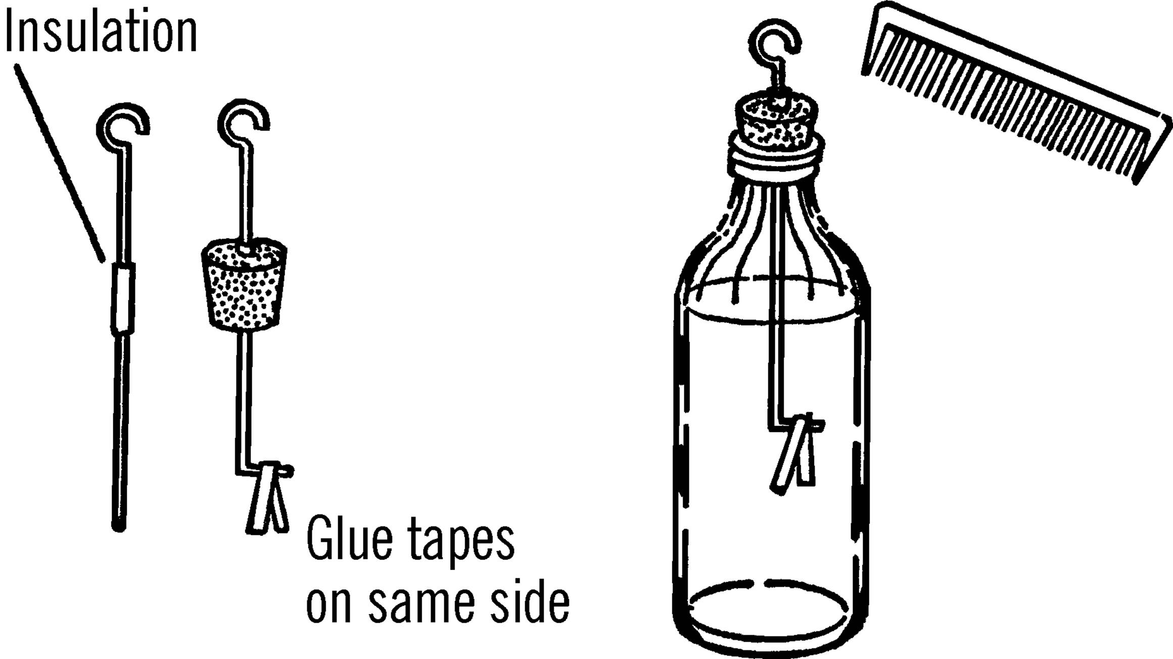
Operation of Equipment: Rub a comb on a piece of wool or flannel. Touch the comb to the loop of the wire. The tapes should become charged. Because the charge on both strips of tape is the same kind, the strips push apart. If you place the charge on the loop correctly, the tapes will remain charged after you remove the pencil.
Can You Work Like a Scientist?
1. Touch the loop. What happens to the charge on the tapes?
2. Rub some plastic, like a plastic bag, with your hand many times. Touch the loop with the plastic and see what happens.
3. Rub some paper. When you touch the loop, do the tapes go farther apart or together? Is the charge the same as the plastic? If so, the tapes should go farther apart.
4. Touch the loop. Now rub a glass test tube with flannel, then silk, and finally wool. Test your electroscope each time. Are the charges alike or different?
5. Does your electroscope work better in dry or moist air? What effect does temperature have on the operation of your electroscope?
6. Does the charge seem to leak away? The cork may be your trouble. Try waxing or shellacking the cork. Is this better? Try a rubber stopper.
7. Some of the charge may leak away from the loop. Get an old Christmas tree ornament. Slip this over the rod. The ornament is round. Does the electroscope keep its charge longer? Try coating the ornament with aluminum paint.
8. When the air is damp, it is a good conductor of electricity. How does this help to explain why static electricity charges seem to leak away?
Pith Ball Electroscope
Purpose: The pith ball electroscope is used to detect the charge of static electricity.
Materials: Small bottle (ink, olive, maraschino cherry, etc.), cork, silk or nylon thread, stiff wire, and a pith ball. The pith ball can be made from the pith (inside) of an elderberry plant; however, workable substitutes are small cork or styrofoam balls about half an inch in diameter.
What to Do: Wrap aluminum foil around the styrofoam or cork ball. Tie a knot in one end of the thread. Thread the needle and stick it through the ball. Pull the thread through and remove the needle. Tie the end of the thread to the wire loop as shown.
Operation of Equipment: You give a charge of static electricity to an object by rubbing it with another object. Bring a charged object near the pith ball and see what happens.
Can You Work Like a Scientist?
1. Rub a piece of plastic with your hand. Can you transfer the charge on the plastic to the pith ball?
2. Can you charge the pith ball by direct contact? By bringing a charged object near the pith ball?
3. Charge the ball. Give the same charge to another object. Bring the object close to the charged pith ball. What happens?
4. Charge two pith balls with an opposite charge. What happens when the pith balls are brought near each other?
5. Rub a black hard rubber comb with fur or wool. The charge on the comb is negative (-). Charge the pith ball with this negative charge. Objects that will attract this negatively charged ball have a positive charge.
6. Now rub various objects with fur, plastic, nylon, flannel, etc. Record the charge of each. Remember to charge your pith ball electroscope with the comb each time.
7. Rub a balloon. What kind of a charge does a balloon carry?
8. What kind of charge does your electrophorus (“Electrophorus”) carry?
9. Charge both pith balls the same. Bring a watch with a fluorescent dial near the balls. What happens? Why? (See the dosimeter in the atomic energy section.)
Electronic Electroscope
Purpose: An electronic electroscope is a highly sensitive instrument for detecting faint static electricity charges. An instrument similar to this is used by the weather bureau for detecting and predicting thunderstorms.
Materials: Neon bulb (NE 2), resistor (47 kΩ), high cutoff pentode radio tube (6AU6), transformer (6 volt-½ amp. filament), heavy copper wire for antenna (size 6), and a disc made from aluminum (about 3” in diameter). Two pieces of plastic or wood (about 3” × 6”) for the base, and bolts and nuts to hold the base together.6
What to Do: The plywood or plastic pieces are separated by nuts used as spacers on the four corner bolts. All the wiring is done on the bottom of the top piece. After the electroscope is completed, the bottom piece is placed in position, and the bolts and nuts are fastened in place. This arrangement prevents your touching any of the wiring and getting a shock. Holes are drilled in the top piece, and all wiring connections are made on the bottom side.
First, fasten the transformer to the base. Next, mount the neon bulb and then the tube on the top side of the base. Tap off the line coming in from the plug (house current) to the transformer.7 This usually is a black wire. Connect a lead from this wire to one side of the neon bulb. This should be done on the bottom side of the base. The other side of the neon bulb is connected to the resistor located on the bottom side of the base. The other side of the resistor is connected to both the plate and screen connection of the tube. (See wiring diagram.)
The other black lead-in wire to the transformer is connected to the suppressor of the tube and the cathode of the tube. The low-voltage wires from the transformer (green) are connected to the ends of the filament heater in the tube. A heavy copper rod or wire is connected from the grid of the tube and mounted upright through the base. This antenna should be about 12” long. A hole should be drilled in the center of the aluminum disc so that the disc will just fit over the copper wire antenna. The bottom base is then held in place by corner bolts and spacer nuts between the two bases.
SYMBOLS: Ne2: Neon bulb, R: Resistor (47 kΩ), 6AU6: Tube, A: Antenna, T: Transformer
TUBE CONNECTIONS: 1: Grid, 2: Suppressor, 3: Filament heater, 4: Filament heater, 5: Plate, 6: Screen, 7: Cathode
Operation of Equipment: In order to understand the operation of the electroscope, we must understand the operation of the tube.
Electricity coming from a house plug is 110-volt alternating current. This is the current that comes into the cathode from socket 7. The cathode gives off bits of electricity (electrons), and because it has many extra electrons it has a negative charge. The wires from the low voltage side of the transformer bring in low voltage current to the filament heater through sockets 3 and 4. The filament heater adds extra energy to the electrons coming off the cathode. In fact, a cloud of electrons form around the cathode. The grid connected to socket number 1 normally does not have a charge. This grid is connected to the antenna. A screen (socket no. 6) is connected to the other side of the transformer through the resistor and the neon bulb. Since its charge is positive, or opposite to that of the cathode, it pulls the electrons from the cathode. The electrons are then pulled from the screen to the plate (socket no. 5). The plate is connected on the same side of the transformer as the screen and thus has the same positive charge. Since the plate is larger than the screen suppressor (socket no. 2), the greater charge pulls the electrons right by the suppressor screen. The suppressor acts to slow down the electrons since it has the same negative charge as the electrons. Like charges repel. When the electrons reach the plate, the electricity flows through the resistor and lights up the neon bulb. Thus, when the neon bulb is glowing, electrons are flowing across the tube.
When the current changes directions, the plate becomes positive and the suppressor negative. Since the electrons are negative, they are repelled by the suppressor and stay on the plate. Thus the tube acts as a gate to let the electricity flow only in one direction.
Modern Safety Practice
Pay careful attention not to touch the exposed wiring: a shock from mains power (AKA line voltage or household wiring) is potentially lethal. Read Note 10 in Appendix E for safety practice around it.
The low-voltage LED electroscope described in Note 31 of Appendix E is a safe and easy alternative to the project described here.
Can You Work Like a Scientist?
1. Normally the grid does not have a charge, so the current flows through the tube and the neon bulb glows. Now, if you rub some object and produce a static electricity charge, let’s see what happens. Suppose you bring an object with a positive charge near the antenna, thus giving the grid a positive charge. Since the cathode has a negative charge, will the electrons flow by the grid to the plate? Remember, unlike charges attract.
2. Will the bulb continue to glow if the charge on the grid is positive?
3. If you bring an object charged negatively near the antenna, the grid becomes negatively charged. The cathode is also negatively charged. Will the grid allow the electrons to flow by? Will the neon bulb continue to glow?
4. Does the electroscope detect positive or negative charges? What does it indicate when the bulb goes out?
5. What kind of charge forms on a black hard rubber comb? Remember, when you rub an object, a positive charge forms on one of the materials, and a negative charge forms on the other.
6. How far away from the antenna will the electroscope detect static electricity charges?
7. Does the distance that a charge can be detected vary with the amount of humidity?
8. Will your electroscope operate as well in a bathroom after a shower as in other rooms of the house?
9. What is the effect of putting hair oil on your hair as far as the generating of static electricity is concerned? Try combing your hair and see.
10.Do you create a static electricity charge when you pet a cat? What kind of charge is formed?
11.Break a lump of sugar in a darkened room. Is static electricity given off?
12.Can you detect the build-up of thunderstorms with your electroscope?
13.Do all cloth materials give off the same type of static electricity charge?
14.What seems to affect the rate at which a static electricity charge leaks off? What kind of material and what shape will retain a charge the longest?
15.Does flowing water have an electrical charge?
16.Is there a static electricity charge built up when a mimeograph or duplicating machine is operating? What causes the charge? What kind of charge is formed? Does it vary with humidity?
17.If you use a 6J7G tube instead of the 6AU6, your electroscope will be more sensitive. The antenna disc is placed on the cap of the tube.
18.Is the distance through which an electronic electroscope will detect static electricity an indirect way of measuring the strength of the charge? Can you devise a scale to measure the strength of static electricity charges?
19.What is the effect of temperature on static electricity charges?
Electrophorus
Purpose: This is a standard piece of equipment used to build up a strong static electricity charge.
Materials: Aluminum cake tin, wood doweling for handle, plastic sheet or rubber sheet (from old inner tube if none other available), piece of fur or flannel.
What to Do: Drill a hole in the bottom of the cake tin. Attach a handle to the tin by nailing through the hole. Lay the rubber sheet on a flat surface.
Operation of Equipment: Rub the rubber or plastic sheet with the flannel or fur for about a minute. Place the cake tin on the rubber sheet. Press down on the inside of the cake tin with your fingers. Then lift the cake tin off the rubber by lifting the tin by its wooden handle. The tin is highly charged.
Can You Work Like a Scientist?
1. Bring your finger near the edge of the cake tin. What do you observe?
2. Does the electrophorus work as well if you rub the rubber with silk?
3. Why did you press down with your fingers? Would it work just as well if you didn’t press down with your fingers?
4. Try your electrophorus out in a dry room. Then turn on the shower in the bathroom. Does the electrophorus work as well if there is moisture in the air.
5. Discharge the electrophorus by letting a spark jump to your finger. Press the tin down on the rubber again but don’t rub the rubber sheeting. Was the cake tin charged again? Why?
6. If you can’t get a good charge, try a handle made out of a candle or some sealing wax.
7. Try your electrophorus on your electroscope. Is the charge negative or positive? Can you get a different charge on the electrophorus?
8. Can you get the electricity to travel from the tin through a wire to the electroscope? Hold the wire with a clothespin.
9. Try your electrophorus on your pith ball electroscope.
10.Drop bits of paper on the cake tin. Does anything happen? Why?
11.A good source for heavy plastic sheets is the plastic typing plate found in each package of mimeograph stencils. School offices and business offices throw these sheets away.8
12.Try making an electrophorus by using an old phonograph record in place of the cake tin. A candle or sealing wax can be used for the insulated handle.
Leyden Jar
Purpose: The Leyden jar stores static electricity over a short period of time. The jar can store up quite a powerful charge.
Materials: Mason jar, tin foil or aluminum foil, ¼” plywood for the jar cover, round brass curtain rod with a brass ball on the end, a short chain, and shellac. If you can’t get a brass rod, use heavy wire.
What to Do: Clean and dry the jar thoroughly. Coat the inside of the jar with shellac. The tin foil or aluminum foil coating should cover only the lower two-thirds of the jar. Before the shellac has completely dried, insert the foil and press it smoothly around the inside of the jar. Coat the lower two-thirds of the outside of the jar in the same manner, shellac, and then cover with foil. Cut foil circles for the bottom of the jar, both inside and out.
Cut a piece of plywood into a circle that will just fit the inside of the jar opening. Cut a second circle about half an inch larger than the first. Glue or nail these together. These pieces form the lid of your Leyden jar. Shellac this lid and drill a hole through it for the rod and chain or the wire.9
Operation of Equipment: The Leyden jar may be charged by touching an object or wire containing static electricity to the ball or loop on the outside of the jar.
You can discharge a Leyden jar by bringing a piece of wire, which is connected to the outside coating, toward the brass ball on the top of the rod.
Modern Safety Practice
A Leyden jar stores a significant amount of electric charge and can give you a severe (potentially lethal) shock. So it is very important to discharge the jar before touching it. For added safety, mount your discharging wire on a long wooden handle so that you do not touch (or come close to touching) the wire.
Can You Work Like a Scientist?
1. Will other types of metal rods and balls work besides brass?
2. What does the chain do in building up static electricity?
3. Can you charge a Leyden jar positively?
4. Can you charge a jar negatively?
5. Can you think of a way to measure the amount of charge stored by the jar?
6. Can you charge your Leyden jar with an electrophorus?
7. Can you store regular electricity in a Leyden jar?10 How about direct current? Be very careful with house current.
8. Does the static electricity in your Leyden jar affect a compass?
9. You can make a simple Leyden jar with just aluminum foil and a glass. (See the dosimeter in the atomic energy section.)
10.You can store more electricity if you stack glass plates with a layer of aluminum between each. The ends of the foil at each of the plates are connected together. This is a capacitor.11
Solenoid
Purpose: This instrument is used to make magnets with electricity from batteries.12
Materials: Hollow tubing, such as a test tube, cardboard tubing, or glass tubing. Also insulated wire (wire that does not have too much resistance).
What to Do: Wrap the wire around the tubing or test tube many times. Connect each end to a battery. A dry cell or a flashlight battery will work; a storage battery or battery charger is ideal.13 The wire can be held in place by tying it or by using adhesive tape.
Operation of Equipment: Place the object to be magnetized in the coil or tubing. Connect up the electricity. Remove the object.
Safety Tips
Don’t leave the electricity on too long. The wire might get hot and cause a burn.
Can You Work Like a Scientist?
1. Does the number of turns have any effect on the strength of the magnet? Test with a magnetometer.
2. What things magnetize the best?
3. What effect does increasing the current have on the magnet?
4. Can you magnetize a watch spring? A file? A screwdriver?
5. Place the nail just inside the coil. Turn on the electricity. What happens to the nail?
6. Try to shake the nail out of the coil while the electricity is on. What holds the nail in?
7. Test the solenoid with a compass. Does it have a north and south pole? Which is the stronger?
8. Does the direction in which you wrap the wire around the tubing have anything to do with the poles?
9. What would happen if you connected the solenoid to alternating current instead of direct current? Use a bell transformer or a train transformer. Your salt water rheostat might work. Check the current with a compass. Place a magnetized object in the coil. What effect does alternating current have on a magnet?
Lemon Battery
Purpose: The lemon battery shows the principle of the battery.
Materials: Strip of zinc, copper strip, paper clips, and a lemon.
What to Do: Connect a wire to each strip of metal with the clips. Insert the copper and zinc strip into the lemon. Connect the lemon battery up to a compass galvanoscope.14
Blotting Paper Battery
Purpose: This simple battery uses simple materials to show the essential parts of the battery.
Materials: Blotting paper, vinegar, paper clips, zinc piece from old flashlight battery,15 and a penny.16
What to Do: Fasten a wire to each paper clip. Soak a small piece of blotting paper in vinegar. Clip the paper clips on the penny and the piece of zinc. Connect the wires up to a compass galvanoscope. Place the blotting paper between the two pieces of metal. A current should flow and affect the compass. Which strip is the positive pole? Can you tell from the compass? Is this the same as the lemon battery?
Modern Safety Practice
Although these are simple electrochemistry experiments, they are still chemistry experiments. Read Note 17 in Appendix E for safety practice around chemicals.
Electric Cell
Purpose: This liquid cell will produce enough power to light a flashlight bulb.
Materials: Mason jar, copper and zinc strip, paper clips, and dilute sulfuric acid. The acid may be purchased from the drugstore, or you may get some from an old car battery. Ask an attendant at a local service station.17
What to Do: Clip the wires to the strips with paper clips. Hang the strips in the acid. Connect the wires up to a flashlight bulb. Do you detect an electric current?18
Modern Safety Practice
Read Note 17 in Appendix E for safety practice around chemicals.
Galvanoscope
Purpose: A galvanoscope is used for detecting very small amounts of electric current.
Materials: For both galvanoscopes shown, you will need very light insulated #22 wire. In addition, you need two needles for the first one, and a razor blade for the second.
What to Do: Wrap about 25” of the wire around a mason jar in a neat coil, leaving a few feet at each end. Tie the wire together with strings as shown. Make a wood frame as shown. In the razor blade galvanoscope the coil is hung from the support. The razor blade is magnetized either with a magnet or electrically. The blade is then hung so that it is parallel to the coil of wire.
In the needle galvanoscope, the coil is mounted on the base. The needles are magnetized and stuck through a small piece of cardboard and are parallel to each other. The poles are opposite. The needles and cardboard are hung by a thread and turn freely through a split in the top of the coil.
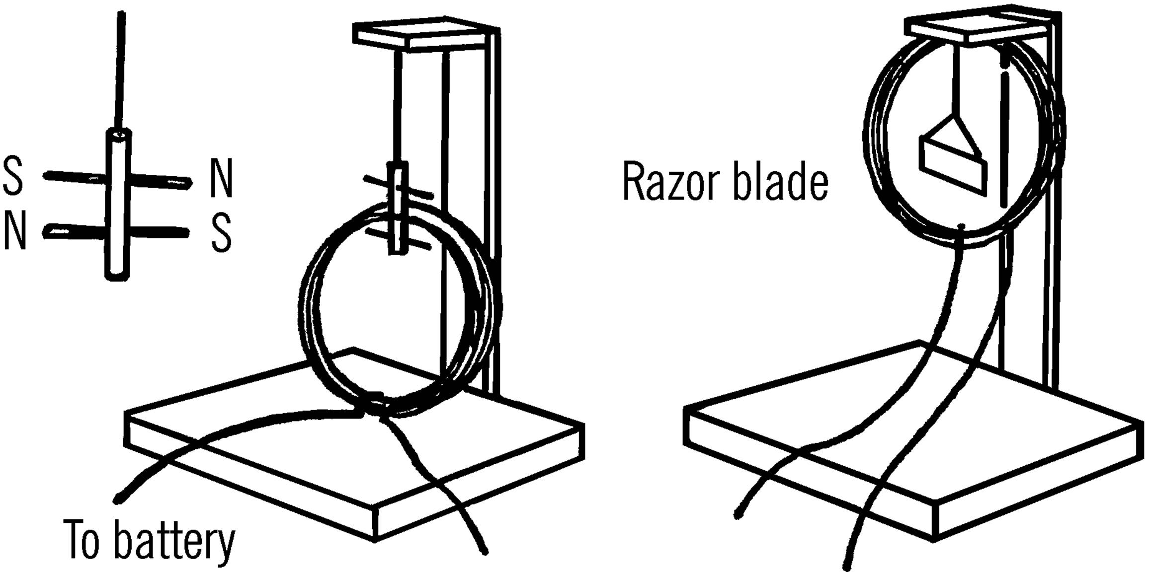
Operation of Equipment: Connect up the power to the free ends of the coil. The coil of wire becomes magnetized when current flows through. The razor blade turns to line up its magnetic field with that of the coil. In the case of the needle galvanoscope, one needle turns to line up with the magnetic force inside the coil. The other needle lines up with the magnetic force outside the coil.
Modern Safety Practice
Razor blades are sharp; use caution.
Can You Work Like a Scientist?
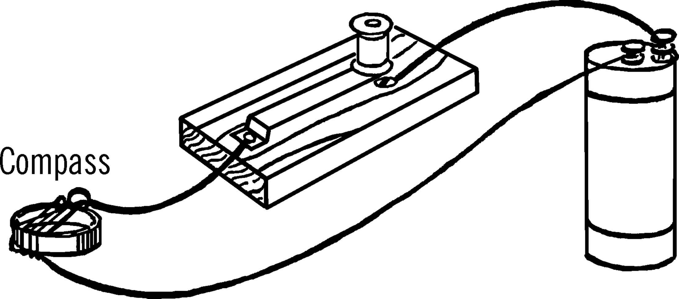
1. If you make a simple compass galvanoscope as shown below, can it detect faint currents?
1. What happens when you switch the wires on the dry cell or the transformer?
2. Does increased current affect the galvanoscope more or less?
3. Can you use this idea to make an ammeter?
4. Work the compass galvanoscope with AC.19
Storage Battery
Purpose: This is a simple type of storage battery. It can be charged and then the charge used to light a flashlight bulb or to ring a bell. The battery can be charged many times.
Materials: Two strips of lead (lead fishing sinkers will do), acid (sulfuric, hydrochloric, or other strong acid), jar, two wires to connect to charger or bell.
What to Do: Use a gallon jug aquarium (see “Bottle Cutter”) or a wide-mouth jar. Fill the jar half full of dilute acid (see instructions about batteries, “Electric Cell”). Hang the fishing sinkers or lead strips from the wires as shown. Connect the wires up to a source of direct current (dry cells, 6-volt car battery,20 battery charger, DC transformer).
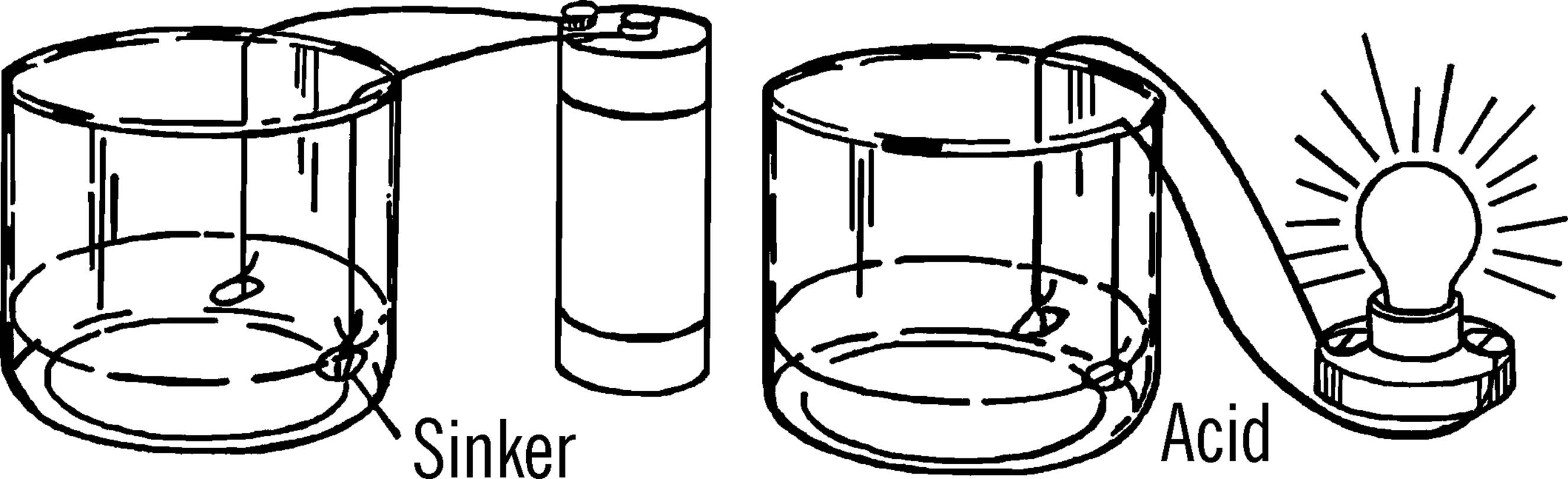
Operation of Equipment: One lead strip or sinker will start to turn brown. This is the positive pole. The brown color is due to the oxygen escaping from the water and joining with the lead to form lead dioxide. One element (sinker) is now lead and the other lead dioxide. Since the poles are different materials, current will flow.
Modern Safety Practice
The acid is potentially hazardous. Take appropriate cautions for working with chemicals (Note 17 in Appendix E), including wearing safety glasses and washing your hands thoroughly afterwards.
See Note 16 in Appendix E about sources of acids.
Can You Work Like a Scientist?
1. What happens after you use your battery to ring a bell?21
2. What happens to the brown sinker when you recharge the battery?
3. Can you charge the battery with alternating current?
4. What happens if, after charging the battery with direct current, you switch the wires and continue to charge the battery?
5. Can you measure the amount of charge in any way?
6. Can you use your hydrometer (“Hydrometer”) to tell how strong your acid is?
7. Can you use one battery to charge another one?
Mercury Switch
Purpose: A mercury switch is used in many automatic electrical devices. When the position of the switch is changed, the liquid mercury flows over to the wires and completes the contact, turning on the electricity.
Materials: Mercury from a thermometer or purchased from a drugstore.22 A substitute for the mercury could be salt water or some other liquid that conducts electricity easily. A small vial or test tube, and a cork.
What to Do: Stick a needle through the cork and make two holes. Push the bare ends of two wires through the cork. Put enough liquid (salt water or mercury) into the vial to partially fill it. Insert the stopper in the vial.
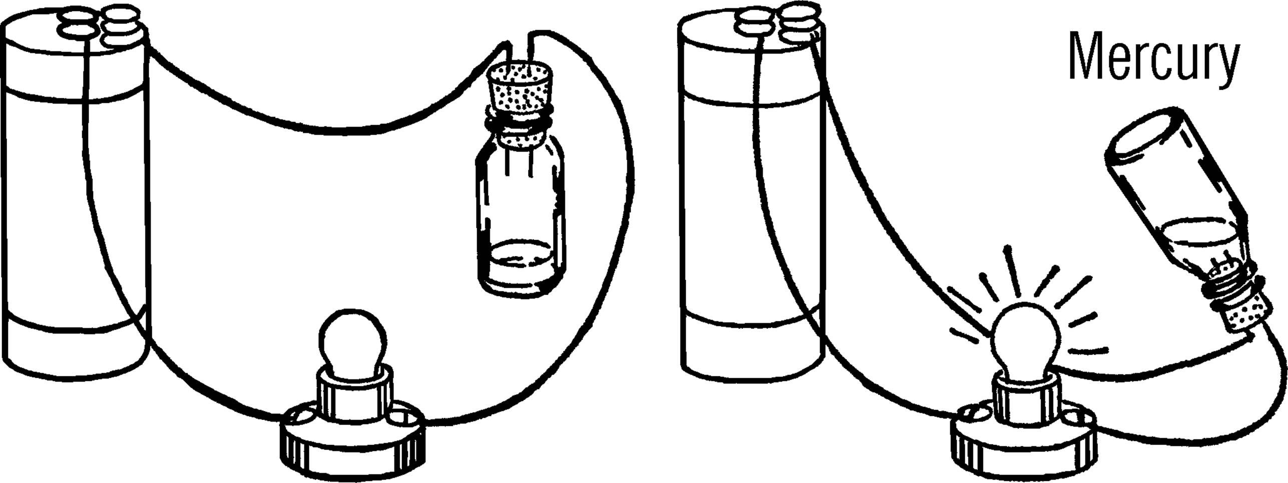
Operation of Equipment: Connect the bare ends of the wire to your circuit of a battery and a small bulb or motor.
Modern Safety Practice
Mercury presents several different health hazards, and is not only harder to obtain, but not recommended for use. See Note 32 in Appendix E for further discussion and methods of building “non-mercury” tilt switches.
Can You Work Like a Scientist?
1. What happens when the vial is in a position so that the liquid contacts both wires?
2. What happens when the vial is turned so that the liquid cannot touch both wires?
3. Mercury is expensive. Can you try other liquids in its place?
4. Would your switch work on current other than that your dry cell produces? Be very careful if you use house current. Don’t touch bare wires.
5. Does the salt water heat? How about the mercury? If you use salt water, be careful the gas given off doesn’t pop the cork out.
Safety Pin Switch
Purpose: A switch opens and closes a path for electricity. When the path is open, electricity does not flow. When the path is closed, electricity flows and operates lights, motors, and other electrical devices.
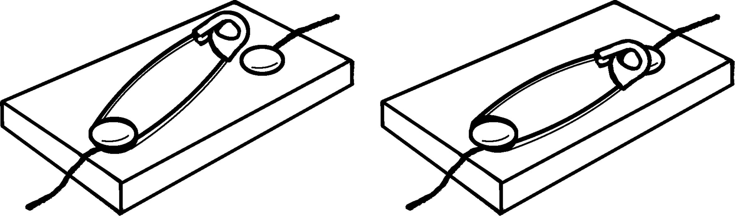
Materials: Safety pin (metal), wire, two tacks, and a board.
What to Do: Remove the insulation from the end of two wires. Wrap the end of one wire around a tack and place the tack through the end of the safety pin. Wrap the bare end of the second wire around the second tack and push the tack into the board so the head of the safety pin makes contact. Wire up your electrical device as shown. Close the switch, and the electricity will flow.23
Modern Safety Practice
As this switch is not insulated in any sense, it can only be used with finger-safe low-voltage circuitry, e.g., circuits running from one or two battery cells. How could you make a safely-insulated safety-pin switch? See “Push Button” for an example of how one might add an enclosure around a switch.
Rheostat
Purpose: A rheostat varies the amount of electricity available for a light or other object using current. This nichrome wire rheostat (see chemistry section) can be used on any amount of current up to 60 volts. However, do not connect the rheostat directly to house voltage without having reduced the voltage (see AC Lamp Bank, “Lamp Bank Rectifier and Battery Charger”).
Materials: Nichrome wire (18” of #20), wood for stand, two bolts, four nuts, and four washers. Your bottle cutter can be used for your rheostat.
What to Do: Make your nichrome wire rheostat as shown in the bottle cutter section (“Bottle Cutter”).
Modern Safety Practice
While this rheostat shouldn’t be used at full household line voltage, it does have exposed wiring. Read Note 10 in Appendix E about safety practice around live wires.
Operation of Equipment: Clip a wire from the electrical device to the nichrome wire. The other wire can be connected on any place along the nichrome wire. The farther apart the connections, the greater the resistance and the lower the amount of current. The closer the connections to each other, the greater the flow of electricity. If the nichrome wire gives too much resistance, use wire with a lower resistance.
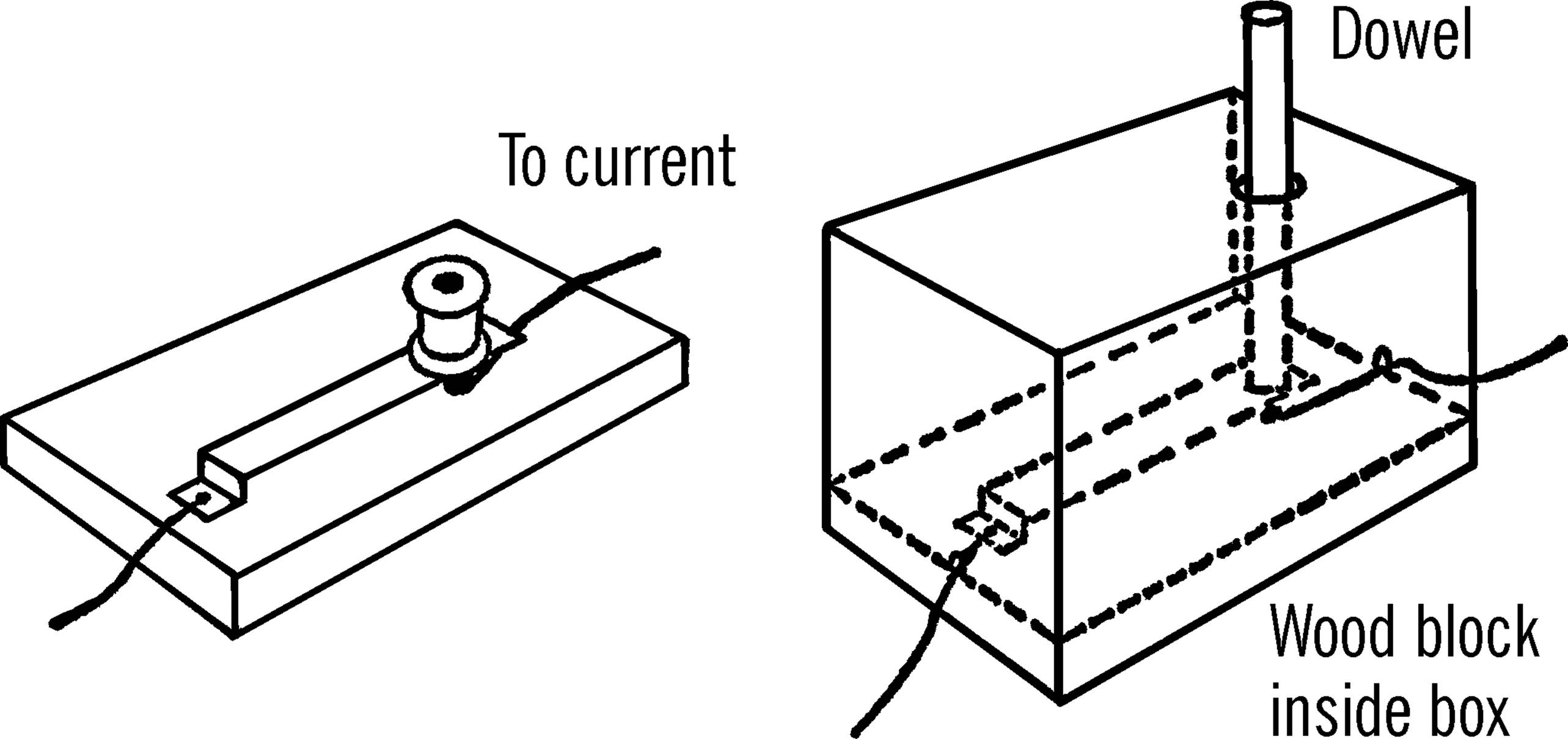
Push Button
Purpose: The push button turns the flow of electricity on and off with a slight movement of the hand. Such a switch can be used with electromagnets, telegraphs, and other devices.
Materials: Wood block for base, two wood screws, a piece of spring brass (other metal will do), and a spool or piece of wood for a handle or knob.
What to Do: Screw the metal strip down as shown. Fasten the knob onto the metal with glue. This knob makes the switch insulated so you won’t receive a shock. A slight push closes the circuit. Release the knob and the circuit is broken. See if you can make the second kind of push button as shown. It is insulated.
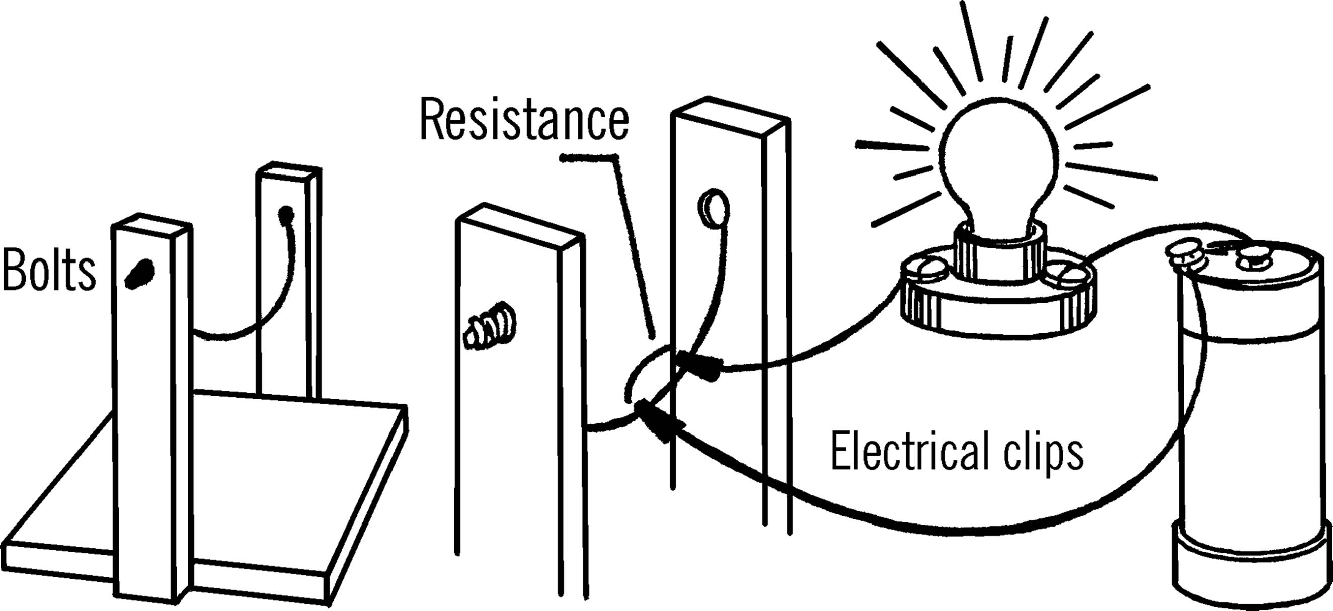
Pencil Rheostat
Purpose: The pencil rheostat reduces the amount of current from a dry cell or small transformer.
Materials: #3 or #4 hardness pencil,24 bell wire, wood base.
What to Do: Cut halfway through the pencil at both ends. Squeeze the pencil with a pair of pliers so the pencil wood breaks at the cut and the lead is exposed. Fasten the pencil down to a wood base. Connect one wire to the point of the pencil or to a place as close to the point as possible. Strip the insulation off the point of the other wire. Connect up the small motor or light as shown.
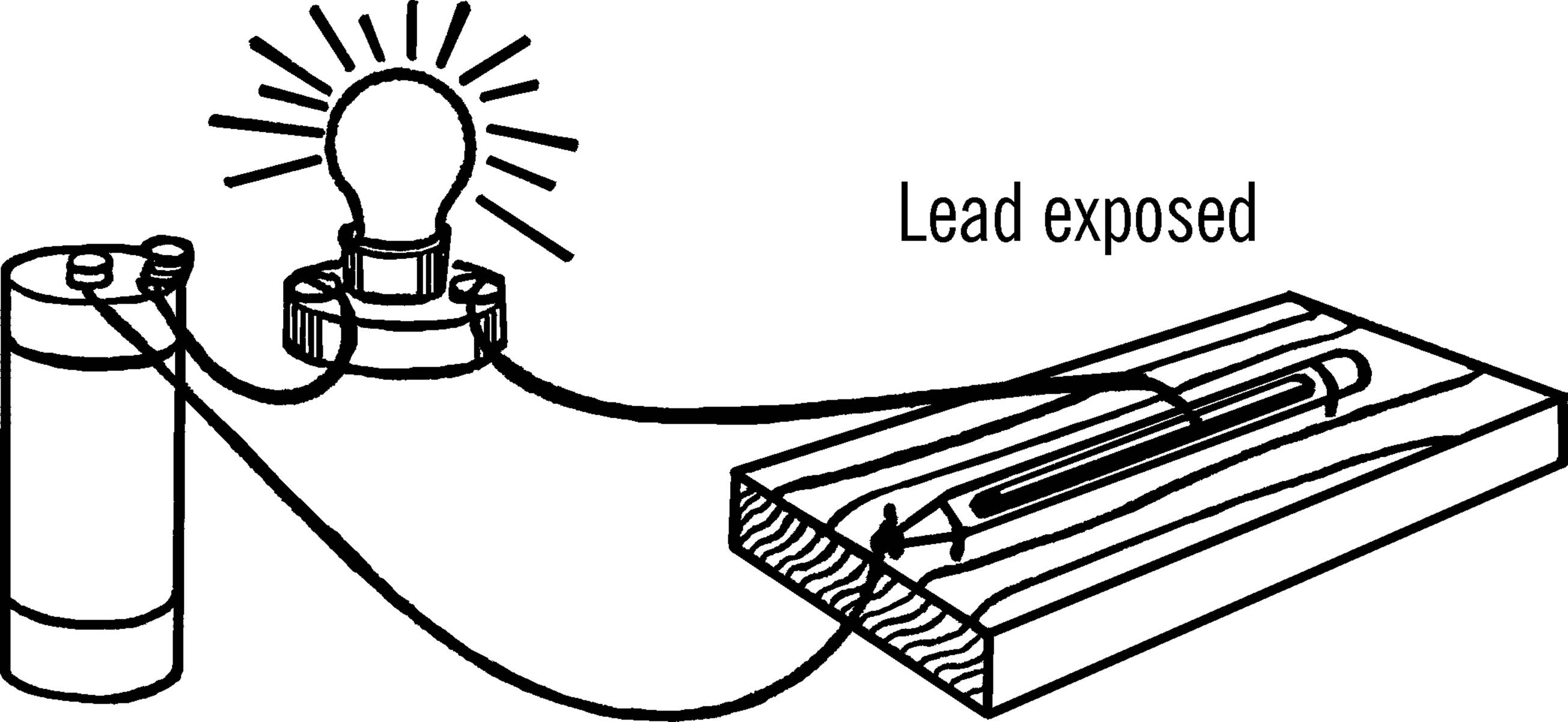
Operation of Equipment: Slide the bare wire along the lead. The bulb increases in brightness as the two wires get closer together. The amount of current is reduced as the wires are moved farther apart. Pencil lead is made of clay and graphite. Graphite is a form of carbon and is a good conductor of electricity. Clay is a nonconductor.
Can You Work Like a Scientist?
1. Is a #1 or #2 pencil a better conductor than a #3 or #4 hardness pencil?
2. Is there more clay in a #2 pencil or in a #3 hardness pencil?
3. Could pencil lead be used for electrodes? Try them.
4. Make a straight line with a soft lead pencil. Can you use this line as a rheostat?
5. Try welding two pieces of tin foil together, using your pencil rheostat as shown.
Modern Safety Practice
If there’s enough heat to weld, there’s potentially enough heat to start a fire as well. Take basic fire safety steps, as discussed in Note 3 of Appendix E.
Current Reverser
Purpose: The current reverser changes the poles or direction of the current. When connected up to motors, etc., the motor will reverse directions. This principle can be used on car motors, cranes, etc.
Materials: Five small tin or brass contacts, two brass or copper strips (other metal will work), and a wooden connecting bar with a spool for a handle, plus wood block for the base.
What to Do: Mount the five connectors as shown. A tack can be used for the contact. It can go through the brass or tin. Attach with a screw the two strips as shown. The strips should be tied together with a wooden connecting piece. A handle can be screwed onto the two strips.
Operation of Equipment: When the handle is moved to the left, contacts 1 and 2 should be touched by strips A and B. When the handle is moved to the right, contacts 2 and 3 should be touched by strips A and B. This reverses the flow of current. Wires from 1 and 3 should be connected together. A single wire then runs to the motor. The second wire to the motor comes from connector 2. Strips A and B are connected by wires to the power supply, a dry cell or transformer power supply.
Can You Work Like a Scientist?
1. Try the current reverser out on a small toy motor.
2. Could you use your current reverser on your electrolysis tank? (“Electrolysis Tank”) What would happen?
3. What would happen if you used your current reverser when electroplating?
4. Connect up your current reverser to your galvanoscope. What happens when you reverse the direction of current?
5. Can you connect the current reverser with the pencil or nichrome wire rheostat and control both the speed and direction of simple motors?
6. Will the current reverser work with alternating current? Be sure to cut the voltage down first with a lamp bank, or with a salt water rheostat.
Conductivity Tester
Purpose: This instrument enables you to test both solids and liquids so that you can find out which will conduct or allow electricity to pass through them. With an electromagnet attachment (see “Magnetometer”) you can measure the strength or conductivity of the solids and liquids.
Materials: Light bulb socket and bulb,25 two pieces of tin,26 source of DC electricity (dry cell, power supply, or battery charger), wire, a bottle with two nails through the cork, and a mounting board.
What to Do: Connect up the materials as shown in the drawing. The pieces of tin should be bent so that they do not touch each other. You do not need to include a push button switch. You can screw the bulb in and out to turn the electricity on and off.
Operation of Equipment: In order to test the conductivity of liquids, pour the liquids into the bottle. If the electricity goes through the liquid, it will make a complete path, and the bulb will light. In order to test bulbs and fuses, lay them across the piece of tin so electricity will flow through the bulb or fuse. If the bulb or fuse is good, the light will glow. Be sure to remove the stopper from the bottle or else remove the liquid when you are testing. You can test the conductivity of solids by laying them across the tin strips.
If you connect an electromagnet in the circuit and use your magnetometer, you can tell which solids or liquids are the best conductors by noting the number of pins the electromagnet will pick up.
Can You Work Like a Scientist?
1. Is salt water a better conductor than fresh water?
2. What other materials added to water besides salt makes water a conductor?
3. Can you make a list of which solids conduct electricity and which do not?
4. Which metals are the best conductors?
5. Can you use your tester to test batteries?
6. By adding just a little salt to your liquid, could you use your bottle as a variable load to cut down the voltage?27
7. Does the temperature of the liquid have anything to do with the conductivity of the liquid? Of the solid?
AC or DC Power Supply
Purpose: A combination of a small transformer and a rectifier makes up a permanent power supply to replace the customary undependable dry cell. A power supply of this type provides both alternating and direct current.
Materials: A 6-volt, center tap, 1 or 2 amp. filament transformer, 1 amp. full wave rectifier, metal for bracket, wood for a base, four Fahnestock clips, and 3 short wires to make connections. The cost of a suitable transformer and rectifier is about $10.00 - $15.00.28
What to Do: Screw the transformer down to the wood base. Connect the two long black leads to rubber-covered electrical cord by soldering the bare ends of the wire and taping the joints with friction tape (zip cord-type on short extension cords). This cord is used to plug into a regular house electrical outlet. Bend a piece of metal (tin, aluminum, etc.) into an L-shape. Drill or punch two holes in this L-bracket, as shown. Screw the bracket to the base. Mount the rectifier to the bracket by sliding the rectifier bolt through the bracket hole and fastening with a nut. Mount your four Fahnestock clips at the end of the wood base with wood screws.
Three wires come out of one side of the transformer. Two wires are green, and the other is yellow. The middle yellow wire is attached directly to the outside Fahnestock clip (#4). Solder the green wires to the AC inputs of the rectifier.29 A wire is soldered from the output terminal of the rectifier30 to Fahnestock clip #3. A short wire is then soldered one of those two inputs to Fahnestock clip #1. A final wire is soldered to the other of the AC inputs and run to Fahnestock clip #2.
Operation of Equipment: Plug the transformer into house current. Now you may attach small lamps (flashlight bulbs), motors, doorbells, buzzers, etc., to two of the Fahnestock clips. The combinations possible are listed below, and the voltage and type of current is mentioned.
Voltage Combinations:
|
Fahnestock clips |
Voltage |
Type |
|
1 and 2 |
7 V |
AC |
|
1 and 3 |
3½ V |
½ wave DC |
|
1 and 4 |
3½ V |
AC |
|
2 and 3 |
3½ V |
½ wave DC |
|
2 and 4 |
3½ V |
AC |
|
3 and 4 |
3½ V |
full wave DC |
The transformer reduces house voltage to about 7 volts. This voltage is ideal for most laboratory or classroom use. The power from the transformer is changing direction 120 times a second. In a loudspeaker or earphones, it sounds like a low hum. You can make a direct connection to this alternating current by connecting up to the combinations shown above.
When the rectifier is connected to the transformer, it changes the voltage from alternating (or reversing) to a smoother kind of current that flows in only one direction. This voltage sounds like a high-pitched hum when heard in a speaker or earphones because it is getting twice as many impulses per second as the voltage from the transformer alone.
The rectifier contains semiconductor diodes that permit the current to flow in only one direction, so the voltage flows first from one terminal into the circuit, and then from the other terminal into the circuit. If you are connected only to one terminal, you will receive only half as much current as when connected to both terminals.
Safety Tips
1. Always use some form of direct current on motors having permanent magnets. Alternating voltages will destroy permanent magnets.
2. Be careful not to cause a short circuit to occur for very long as it can cause the transformer to burn out. When either the transformer or rectifier becomes uncomfortably warm to the touch, check for a short circuit or too large a load on the circuit (too much connected to the transformer).
3. There is no danger of shock from this power supply if the cord to the transformer from the outlet plug is properly connected.31
Modern Safety Practice
1. While building a power supply is an excellent and educational project, it is worth considering that modern efficient plug-in power supplies will likely cost less and be safer for later use. Related question to investigate: What is the efficiency of this power supply? How can you measure it?
2. This is a basic power supply design that does not have any kind of fuse (or other overcurrent protection) built into it. For what reasons is this problematic, from the standpoint of safety? Could a fuse protect the transformer in the case of the short circuit described previously?
3. When adding a single fuse, it should go on the primary side of the transformer. Why? Would it make sense to also have a second fuse on the secondary side of the transformer? How can you calculate what fuses you need, in terms of current rating?
4. Make sure that you do not leave any exposed wiring, particularly on the “primary” (line voltage) side. Read Note 10 in Appendix E for safety practice around exposed wiring.
Can You Work Like a Scientist?
1. Wind many turns of wire around a piece of hard steel (file, screwdriver). Which combination of connections makes a permanent magnet?
2. Which combination of connections will destroy a permanent magnet placed in this coil?
3. Poles 3 and 4 can be used for a source of power for electroplating and electrolysis. Connect the item to be plated to the negative pole. The other electrode (anode) is connected to the positive pole.
4. Can you use a compass to detect which is the positive and which the negative poles of the other combinations?
5. In electrolysis, we can tell where hydrogen is formed because we get twice as much hydrogen from water as we get oxygen. Why? Which pole releases the hydrogen? See “Electrolysis Tank”.
6. Is a compass affected by alternating current?
7. Can you use your nichrome wire rheostat to vary the amount of electricity? With this can you change the speed of motors, etc.?
Variable Load
Purpose: To reduce the amount of voltage that comes from a wall plug so that it is safe and can be used to run small motors and other equipment that normally require a dry cell.32 The dry cell is expensive, is not a dependable source of electricity, and can easily be shorted out. Remember a dry cell is direct current (DC) and the electricity from a transformer is AC.
Materials: Two porcelain light fixtures (one with a pull chain), a 6’ extension cord, and light bulbs with different wattages.
What to Do: Buy two porcelain light fixtures from a hardware store, one plain and one with a pull chain. Cut the socket end off a short extension cord. Divide the wires. Use short pieces of the wire to connect the porcelain fixtures in series as shown in the drawing. The two ends of the wire at A and B are left unconnected.33 These ends can be connected to a motor or piece of electrical equipment. They can be clipped together, and the socket of one of the fixtures can be used for the amount of electricity needed.
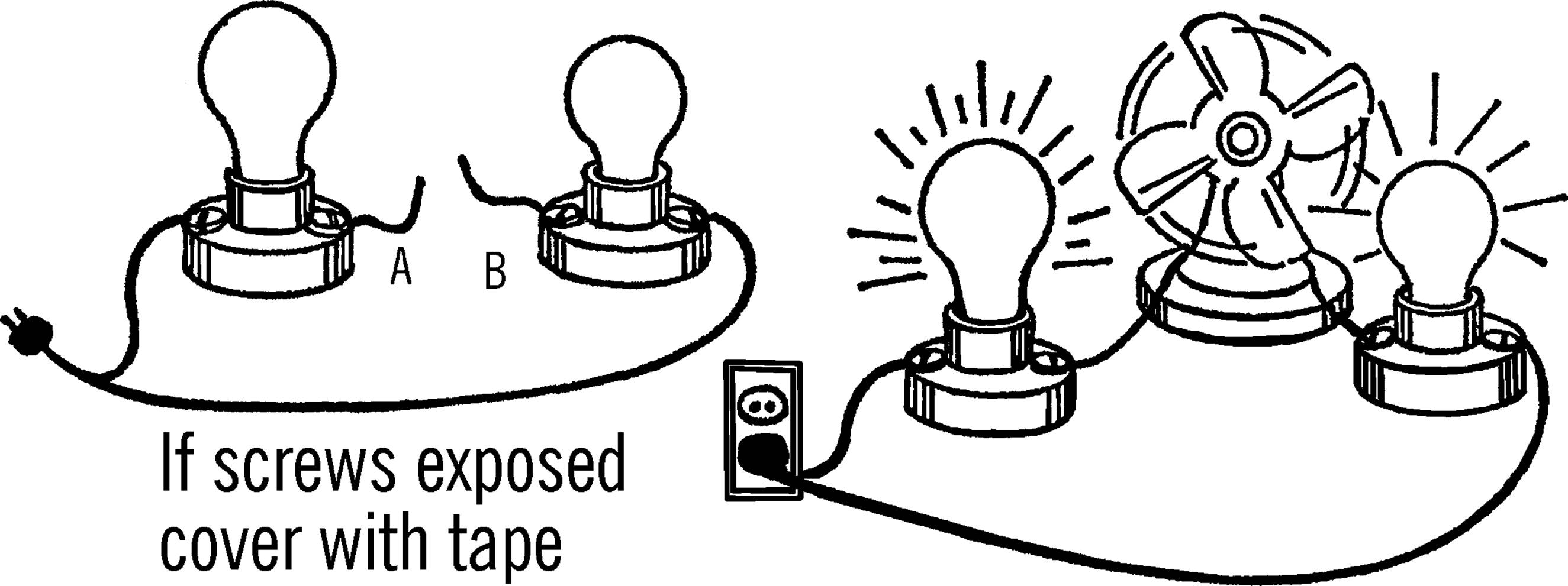
Operation of Equipment: Turn off the electricity by pulling the pull chain. Connect wires A and B to the piece of equipment you wish to operate. Put a large bulb in one fixture. Put the smallest bulb you have in the other fixture (7- or 15-watt size). Plug in the extension cord to a wall plug. Now turn on the electricity with the pull chain. If the current isn’t strong enough, put a larger bulb in the fixture instead of the small one. Increase the size of this bulb until you get the desired amount of electricity. If you wish to plug directly into the line, connect wires A and B. Screw a two-hole plug into one of the fixtures. Now connect directly to this plug.
Safety Tips
1. Be sure you do not work anywhere near a sink or a radiator that might be grounded.
2. Do not touch any bare wires when electricity is turned on.
3. Screw the porcelain fixtures on a board after they are connected up.
4. If the screws on the fixtures are exposed, cover them with electrical tape.
5. Be sure you have one light bulb connected on each side of wires A and B. Then even if you accidentally touch both wires, you will receive only a small amount of electricity.34
6. Never work with electricity if you are standing on damp ground or on a cement floor. Both are good grounds. Electricity could pass through you to the ground.
Modern Safety Practice
In addition to the safety tips listed above, never operate this equipment without easy access to a electrical cut-off switch (e.g., wall switch or circuit breaker panel) that can disconnect power if needed. Read Note 10 in Appendix E for safety practice around exposed wiring.
Better, follow the advice from “Modern Safety Practice” and use an isolated variac to power the equipment.
Can You Work Like a Scientist?
1. You have connected the two lights plus wires A and B in series. The electricity, even though alternating current (going back and forth many times a second), has to go through each one of the bulbs in order to make a complete path. Do the bulbs light up as brightly as they normally do in a lamp?
2. Normal house current has a voltage of about 115 volts. In series, each bulb uses part of the voltage, or electrical push. If you have one bulb in the line, it would get all 115 volts. If you have two bulbs in the line, what is the voltage?
3. You can check your answer. Put in two bulbs of the same size. Connect wires A and B together. Do both bulbs light up to full brightness? Are both bulbs getting their share of the voltage? How do you know?
4. The amount of electrical current flowing is called the amperage, or amps. The electricity has to flow through each lamp. The bulbs act like valves or water faucets. The small bulb lets only a small amount of current through. A large bulb lets more. Test this. Connect wires A and B to a fan. How fast does the fan go when you use a little bulb? How fast does it go when you use a big bulb?
5. Does it make any difference if you use one large and one small bulb or two small bulbs? Does the large or small bulb control the amount of electricity?
6. If you connect a fan up to wires A and B, does the fan increase in speed with the larger-size bulbs? Does the amount of wind given off by the fan also increase?
7. Can you use this wind to turn an anemometer? (See “Anemometer”.)
8. Can you use this principle to measure the amount of current flow (amps)? An instrument for this purpose is called an ammeter.
9. If you connect another porcelain fixture in series with the two you already have, what voltage will each receive? Will this have any effect on the fan? Can you devise a voltmeter from this?
10.As you add bulbs in series, do the lights become brighter or weaker? Is there a change in amperes (current flow) or voltage (push behind current)?
11.How much voltage does each light get in a string of Christmas tree lights if they are wired in series? There are eight bulbs in a string. How much voltage would each get if there were ten in the string? Would the string last longer if there were ten instead of eight bulbs in the string? In which case would the bulbs glow the brightest? Try this and see. You may be able to save much money on Christmas tree bulbs.
12.Connect up your fan measuring device to the Christmas tree string. Can you determine the flow of electricity and the voltage?
Lamp Bank Rectifier and Battery Charger
Purpose: The lamp bank rectifier changes normal house current (AC) into direct current (DC) which then can be cut down to any desired voltage by the nichrome wire rheostat. The rectifier can be used to recharge storage batteries.
Materials: Two porcelain fixtures, two light bulbs, large jar (bottom of gallon jug—see “Bottle Cutter”), wood for base, ¼” plywood for jar lid, and a strip of aluminum and lead.
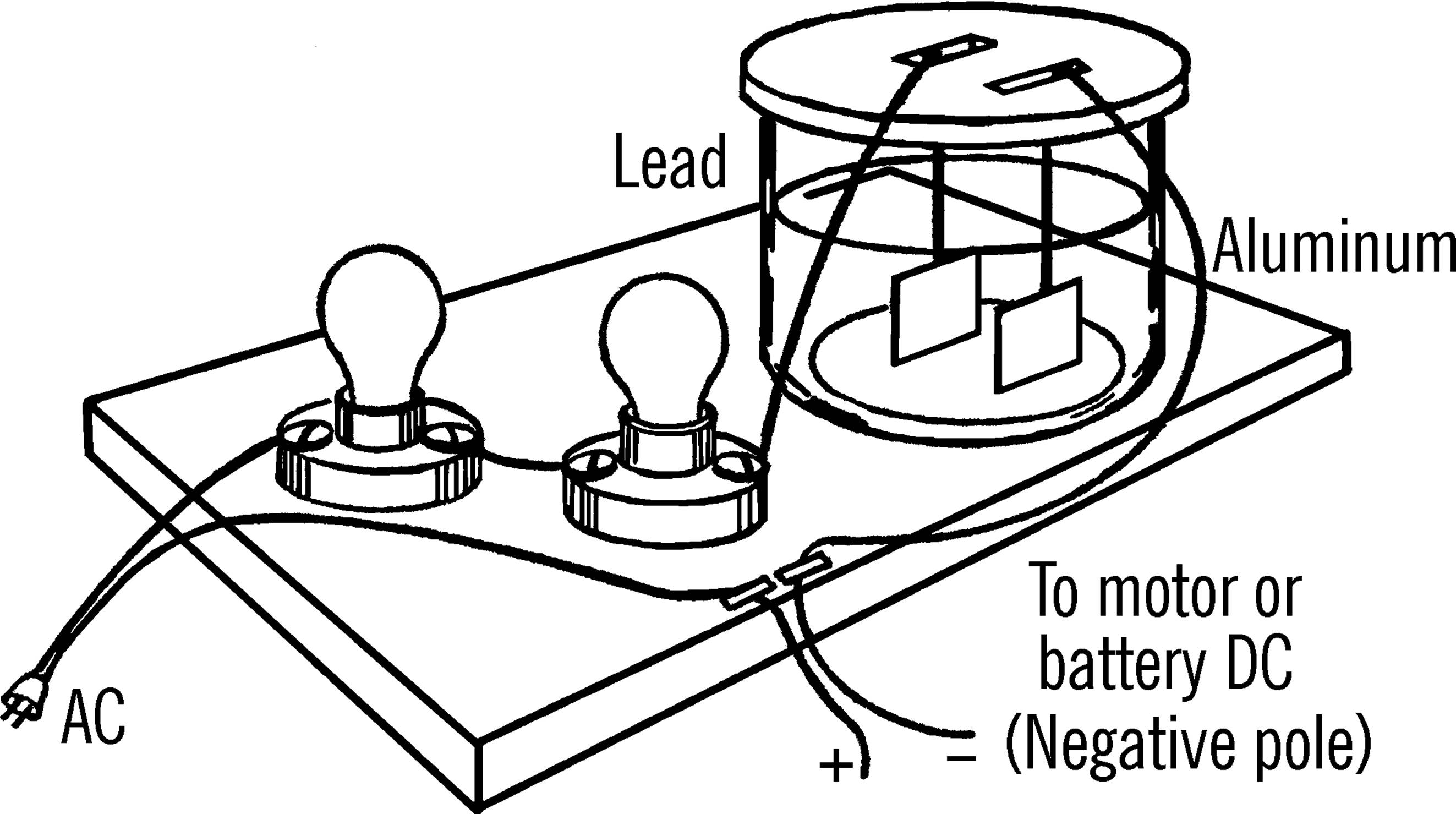
What to Do: Wire up the fixtures as shown. The lid to the jar can be made by cutting one piece of plywood to just fit the jar and a second piece a little larger. These are glued or nailed together. Cut slots for the aluminum and lead strips. This lid should be coated with paraffin to protect it from chemical action. The electrolyte is a strong solution of sodium bicarbonate or baking soda. A package costs about $3.00 at a grocery store.
Operation of Equipment: This rectifier allows current to flow one way but not the other. When the current is such that the lead electrode is positive and the aluminum negative, the current flows through. When the current reverses, the aluminum pole becomes positive. Oxygen gas is formed, coating the electrode with aluminum oxide. Aluminum oxide is a very poor conductor of electricity, so this stops the passage of current back again. This action happens in an instant. This works like a valve, changing the current to direct current.
When charging a storage battery, always connect the negative pole of the battery to the aluminum electrode. The rectifier works well unless too much current is passed through. The electrolyte then becomes too hot.
Modern Safety Practice
This apparatus also involves live AC power from the wall (Note 10 in Appendix E) and requires a cut-off switch. Again, it would be ideal to power it through an isolated variac. (See “Modern Safety Practice”.)
Can You Work Like a Scientist?
1. This lamp bank rectifier uses only one-half of the alternating current. Can you design four such rectifier cells in order to use completely the alternating current?
2. Can you use this rectifier to electroplate?
3. Can you use this rectifier to run your electrolysis tank?
4. You get a small amount of current at high voltages with the lamp bank. Try a small bell transformer or train transformer in its place. This will lower the voltage and still give you enough current to run simple motors, etc.
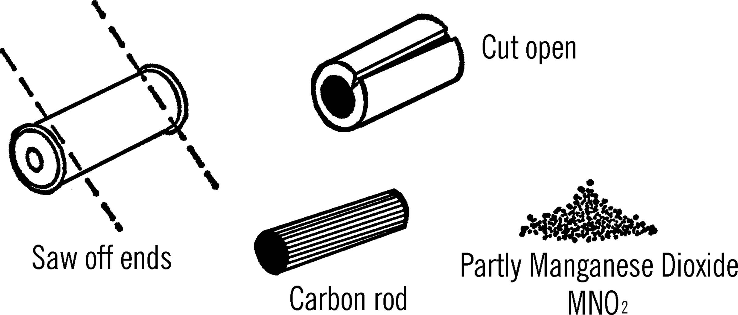
Carbon Rods—Carbon Electrodes
Purpose: Carbon rods are used in electrolysis tanks as electrodes. They are excellent conductors of electricity and do not break down in acids as metal does. Carbon rods are also used for arc furnaces, sensitive microphones, and as resistors.
What to Do: Saw off the ends of a flashlight battery.35 Cut the cover open with tin snips. This metal is probably zinc. Save this zinc, as it comes in handy for experiments. The black rod in the center is a carbon rod. You will get a very large carbon rod out of a dry cell battery.
Electrolysis Tank
Purpose: Electricity is passed through a liquid, and gases are given off at the poles or electrodes. This is a good method of collecting hydrogen and oxygen.
Materials: Wide-mouth jar, two carbon rods from flashlight batteries,36 zip cord (wire covered with rubber),37 and paraffin (you can use melted candle wax).
What to Do: Cut off the top of the jug (see “Bottle Cutter”). Divide the zip cord into two pieces. Wrap the bare end of each wire around the end of a carbon rod. Place the rods in position as shown and melt paraffin into the bottom of the jug. (You might use a piece of cardboard to help support the rods while the paraffin cools.) The loose ends of the zip cord should come up on opposite sides of the jug.
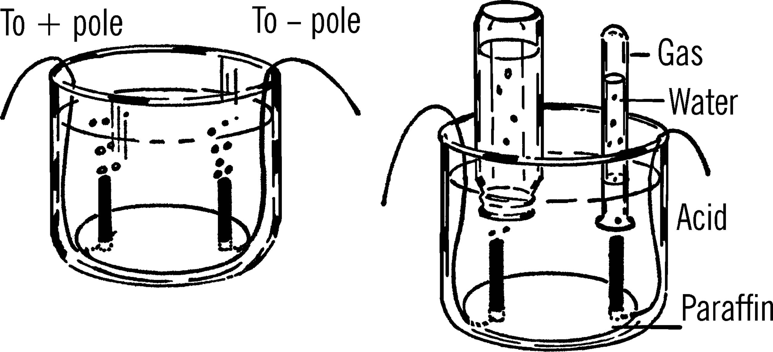
Operation of Equipment: Connect a source of power (dry cell, storage battery, DC transformer) to the wires. The liquid should be an acid or a dissolved material that will conduct electricity. Suggestions are: sulfuric acid, hydrochloric acid, washing soda, baking soda (sodium bicarbonate).
Gases will come off the ends of the rods. Hydrogen will come off one rod and oxygen off the other. In order to collect the gases, place a baby bottle or a test tube filled with water over the rod. As the gases rise, they force out the water, and the water is replaced with the gas being collected. The bottle is then filled with the gas collected.
Try lighting a match to the gas in each bottle. Which bottle contains hydrogen? Why do you have water in the bottle and funnel before you collect the gas? Which bottle will fill faster? Why? What will happen if you switch the poles when the bottles are half filled? If you test with a match, be sure to wrap a towel around the bottle containing the gas. This is just in case the bottle should crack.38
Test Tube Electric Motor
Purpose: This type of motor was one of the earliest to be built. From this working model the junior scientist can discover the principles of an electric motor.
Materials: Three 6” spike nails, 20 feet of cotton-covered wire (or bell wire),39 a cork, a test tube, a thin copper sheet (about 1” × 2”), four short nails, wood for the base, and a ¼” bolt and nut about 6” long.
What to Do: Drill a hole in the center of the board and then drive one of the spikes through the hole. Work a hole in the end of the cork so that the bottom of a test tube will fit tightly in the hole. A second hole should be worked in the side of the cork so that the bolt will fit tightly in the hole as shown. Place the test tube, cork, and bolt over the spike. Drive the other two spikes for the field magnets into the wood base. The spikes should be spaced so that the ends of the bolt will just miss the heads of the spikes.
Wrap about forty turns of wire around each end of the bolt. Notice the direction the wire is wound. This is very important. The copper strip is cut in half to make two pieces ½” × 2”. The strips are placed on the opposite sides of the test tube near the opening of the test tube. The two strips can be held in place by wrapping a strip of tape around the bottom edge. Insert the bare ends of the wire from the armature under the copper strips as shown. Wrap a piece of tape around the top of the copper strip to hold the wires firmly in place.
Now wrap the two field magnets. Again, be sure you wrap the wire in the direction shown in the drawing. The ends of the wire from the small nails to the copper sheet are bare. They should be bent so that each comes in contact with one of the copper strips. When the armature is turned crossways to the two spikes, the bare wires should not touch the copper strips.
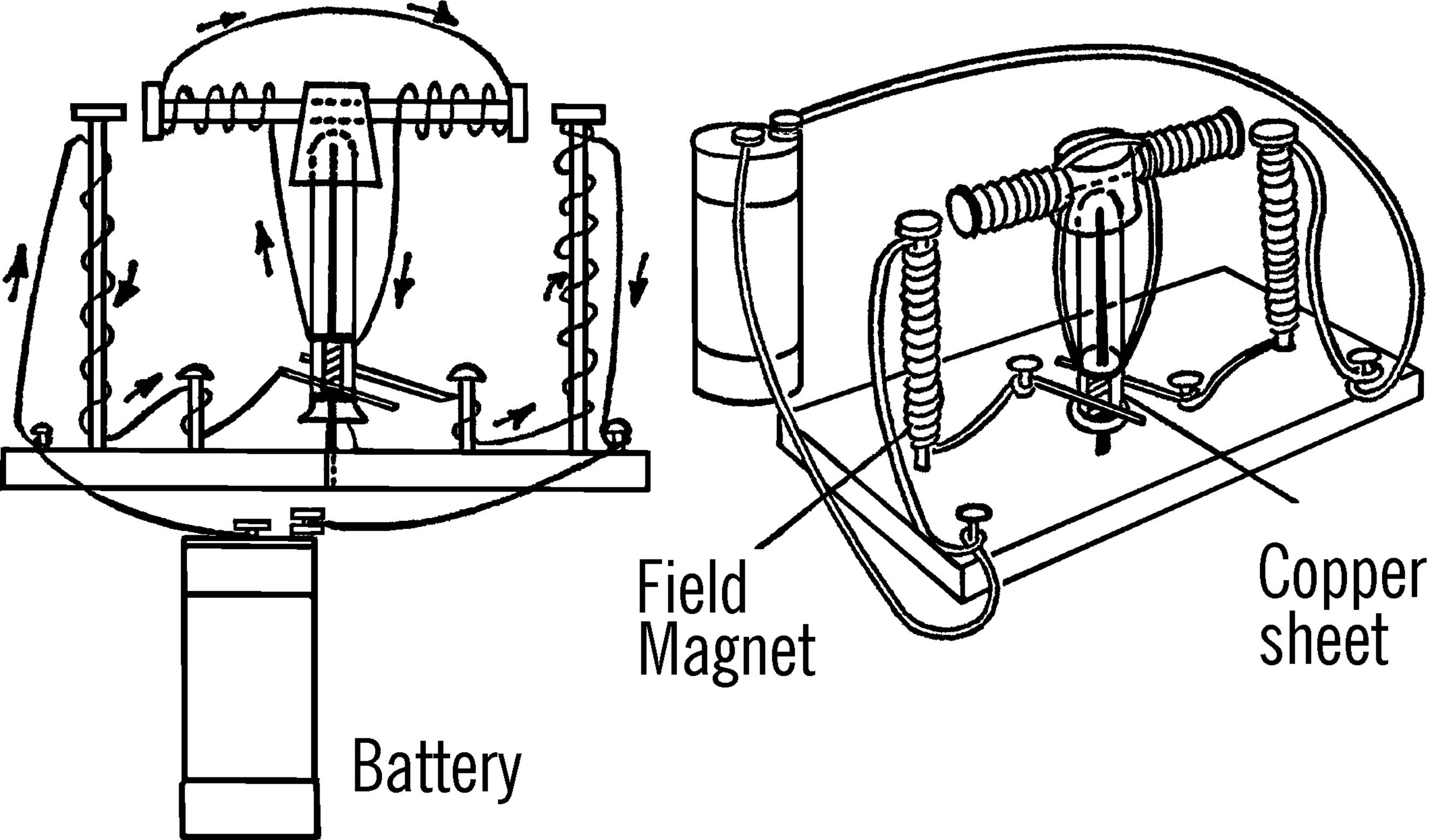
Operation of Equipment: Connect the ends of the wires to a dry cell battery or a three-volt direct current power supply. You may have to adjust the bare wires touching the copper strips or the distance from the heads of the spikes to the bolts in order for the armature to turn. You may have to bend the ends of the two field magnet spikes toward or away from the bolt.
Can You Work Like a Scientist?
1. Can you use a compass to check to see whether the heads of the spikes are north or south electromagnetic poles? Do they ever change? Try turning the armature and checking again.
2. What are the poles of the armature? Again check the ends of the bolt with a compass. Do these poles change when the armature turns?
Bolt and Nut Motor
Purpose: This type of motor can be used to lift objects and to drive small machines.
Materials: Three ¼” bolts about 2¾ inches long, five nuts, eight washers about ¾” in diameter, twenty feet of cotton-covered or bell wire, heavy metal for brackets, finishing nail about four inches long, eight-inch piece of size 8 copper wire, short piece of ½” wood dowel, copper strip about 1” × 1”, screws, and wood for the base.
What to Do: Have a hole drilled in the center of one of the bolts just large enough for the finishing nail to fit in. A machine shop will do this for you.40 Make the metal brackets to hold the armature. Drill a hole through the end of the wood dowel so that a short piece of dowel will slide over the finishing nail. Fasten two strips of thin copper sheeting on each side of the dowel. These strips can be glued or fastened on the dowel by wrapping thread around the ends. Wrap about forty turns of wire around each end of the armature bolt. Be sure the armature is wrapped exactly as shown in the drawing. The direction of the turns is important. The free ends of the armature wire are fastened to the two copper strips on the dowel. It is best if they are soldered.
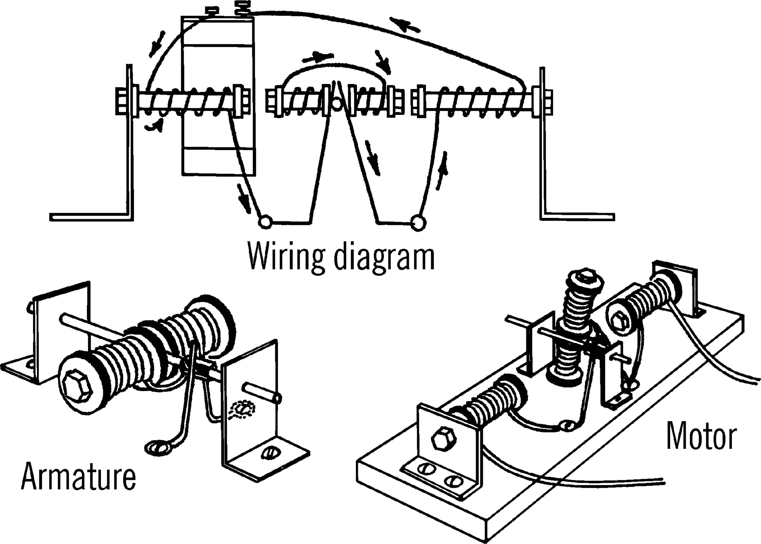
The heavy copper wire serves as brushes. The two pieces are held in place by wood screws in the base. The heavy wire brushes should be bent so that they make contact with the copper strips on the dowel.
The field magnets are wrapped as shown. The brackets can be moved back and forth until the heads of the bolts from the field magnet and the armature just miss each other. One wire from the field magnet goes to the battery. The other wire is soldered to the heavy wire brush. There should be about 100 turns around each field magnet (bolt). It is important that this coil be wrapped in the right direction.
Operation of Equipment: A piece of rubber tubing can be slipped over the end of the center nail to serve as a pulley. A rubber band can be used to connect the motor to toys. A cord can be wrapped directly around the shaft in order to use the motor to lift things.
Can You Work Like a Scientist?
1. What happens to your motor if you connect the current reverser switch to the motor?
2. Can you vary the speed of the motor by using some kind of resistance or rheostat?
3. How much weight can your motor lift?
4. Will your motor start without your help, or do you have to turn the armature?
Doorbell
Purpose: An electric bell not only demonstrates one of the uses of an electromagnet, it also can be used to indicate by sound when an electric current is flowing. The bell can be used in biology for conditioning experiments.41
Materials: Twelve feet of cotton-covered or bell wire, ¼” bolt about three inches long, two large nuts and washers, hacksaw blade for the clapper; nuts, bolts, and wood for the rest of the doorbell, a small metal funnel for the bell, and a long bolt.
What to Do: Drill a hole in a block of wood large enough for the bolt. Insert the bolt in the block of wood and fasten in place with
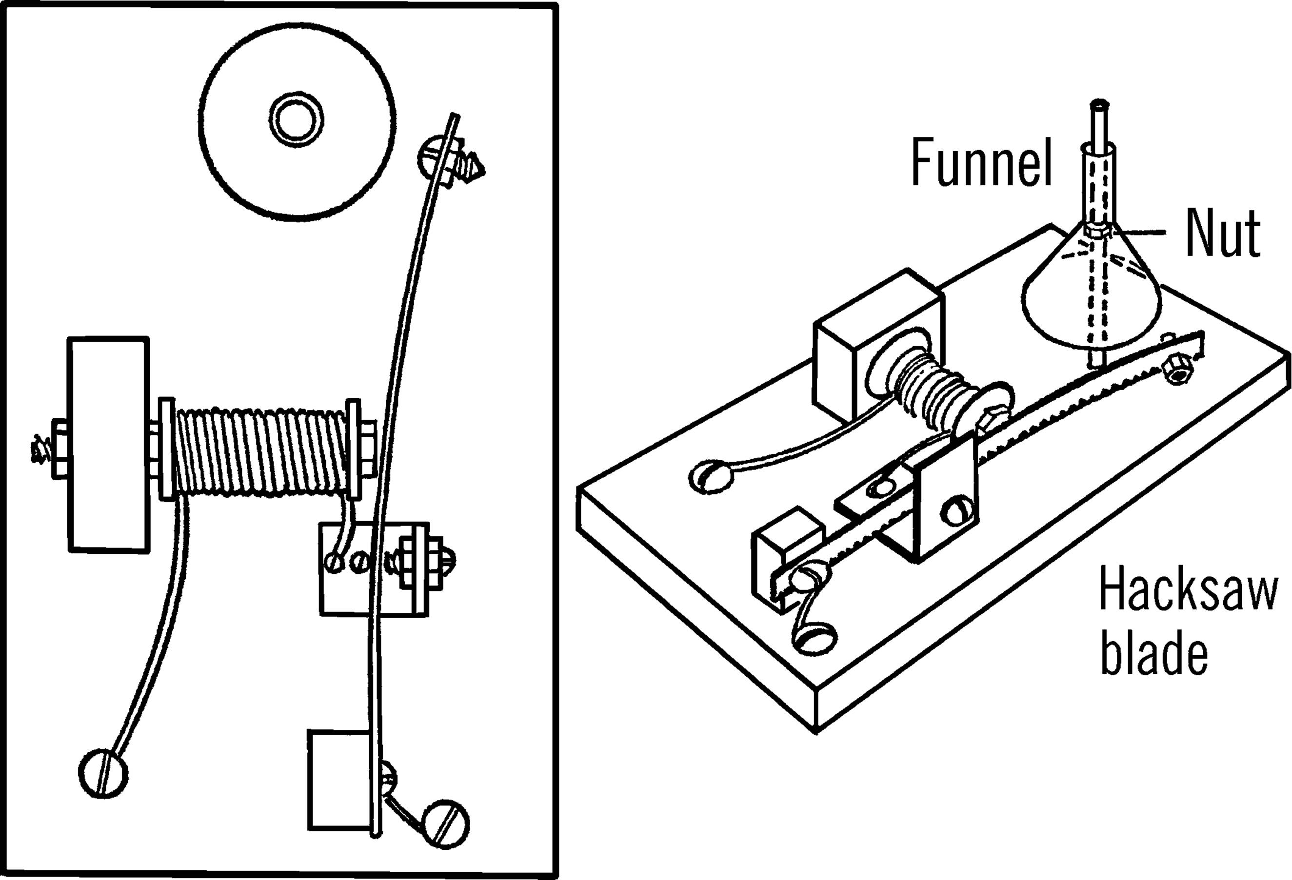
the nuts as shown. Be sure you have the washers in place. Wrap about 140 turns of wire around the bolt. Nail the block of wood to the wooden base.
Drill a hole in the end of a hacksaw blade and fasten the blade to a block of wood with nails and a screw. A small bolt and nut should be fastened in place near the striker end of the blade. Another small bolt and nut is used for a contact point. This bolt and nut is held in place by a tin bracket.
Figure the best location for the bell. Drill a hole in the wood base and insert a long bolt. Thread a nut on the bolt and then hang a small funnel over the bolt.
Operation of Equipment: Connect the bell up to a push-button switch and a dry cell. Will the bell work on alternating current? Try connecting the bell up to your power supply.
Electric Buzzer
Purpose: The buzzer can be used as a sounder for a telegraph set. It has other uses when connected with a push-button switch.
Materials: Three-inch bolt, two large washers, two nuts, twelve feet of bell wire, one-half of a hacksaw blade, heavy copper strip, screw and nuts for the contact point, and wood for the base and supports.
What to Do: Wrap the coil around the bolt as you did in making the doorbell. Fasten the bolt and coil through a hole in the base. Fasten the part of the hacksaw blade to a support with a screw. Drill a hole in the end of the copper strip and fasten the contact screw as shown. Fasten the other end of the copper strip to the tall support. Connect up the wires and push button as shown.42
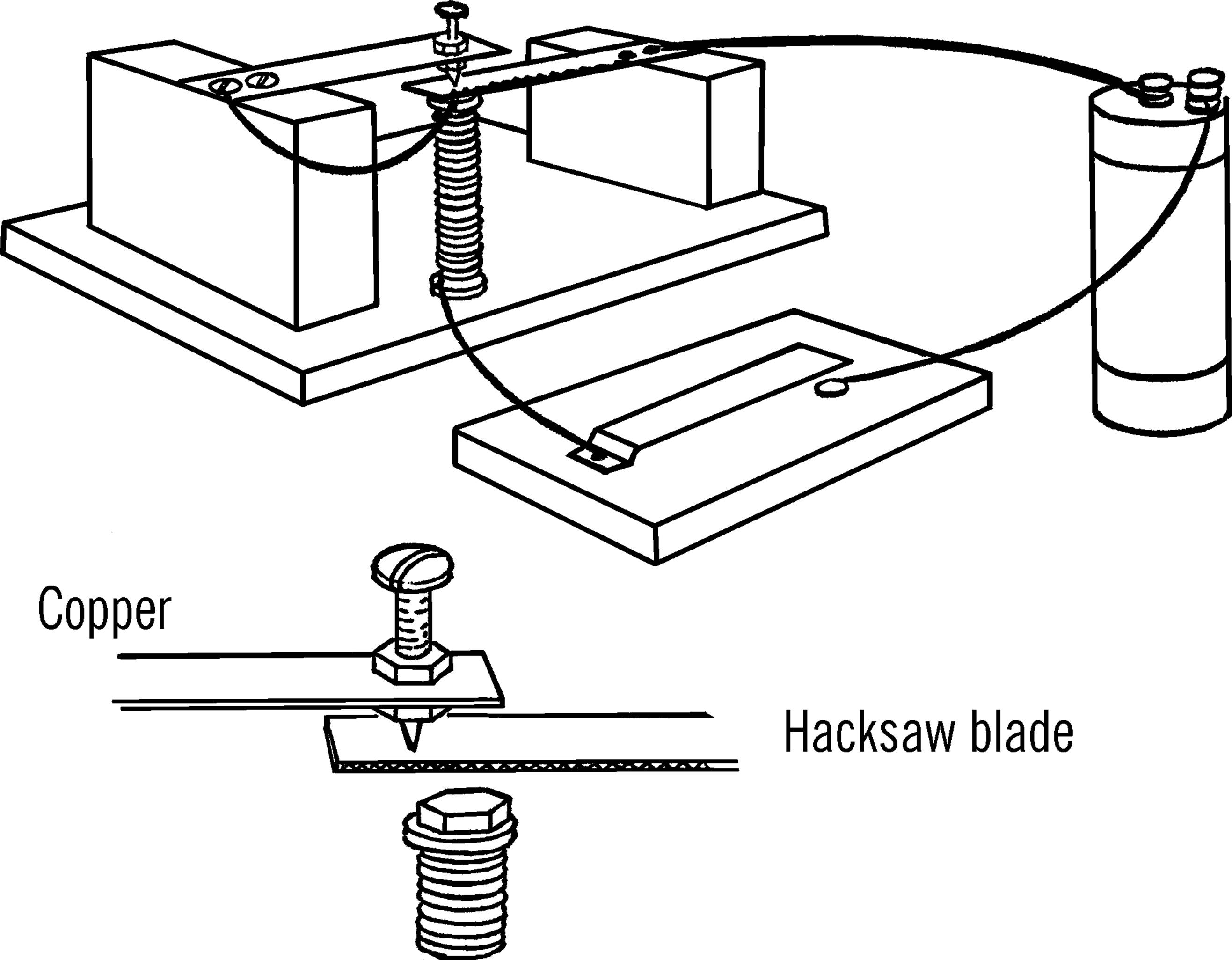
Operation of Equipment: When you press on the push button, electricity flows through the switch and then through the coil. The electricity goes through the copper strip, the contact screw, the hacksaw blade, and then back to the battery. The coil is magnetized and pulls on the hacksaw blade. This breaks the complete path. The coil loses its magnetism, and the blade flies up to the contact screw. The circuit is then complete and the process is repeated.
Can You Work Like a Scientist?
1. Hold one end of a ruler over the edge of the table. Pluck the ruler. Does the ruler make a sound? See if you can make the ruler give off a very high-pitched sound. What causes the sound?
2. How does the movement or vibration of the ruler compare with the movement of the hacksaw blade? Why does the blade produce a buzz?
Telegraph Key
Purpose: A telegraph key is used to make or break a complete electrical circuit or path. A light or sounder plus a source of electrical power are usually connected in the electrical circuit.
Materials: Tin or copper strip, two round-head wood screws, wood for base, cotton-covered wire, flashlight bulb and socket.
What to Do: Bend the tin or copper strip as shown. Punch a hole in the short end of the strip and then fasten the strip and a wire lead with a wood screw. A second wood screw is used for a contact. A wire is also connected to this screw. When you press down on the end of the metal strip, a complete electrical path is made and the bulb will light. A dot is made by a short blink of the light. A dash is a long blink of the flashlight bulb.
Telegraph Sounder
Purpose: A sounder is connected in a path with a telegraph key. As the complete path is made and broken with the key, sounds are produced. From this sound code a telegraph operator can send or receive a message.
Materials: Cigar box, three-inch bolt, two washers, and two nuts, for the magnet coil. Long narrow bolt, two nuts, and a screw eye for the clapper. The sounder is made from a block of wood and a glass microscope slide, 12’ of bell wire.
What to Do: Make your set as shown. The clapper is held against the glass plate by a rubber band. The other end of the clapper swings back and forth in the screw eye.
Telegraph Solenoid Sounder
Purpose: The solenoid sounder is sometimes used with a telegraph key instead of a regular sounder and flashlight bulb. Its advantage is that the sound can be heard for a greater distance.
Materials: Narrow steel or cardboard tubing, cotton-covered wire, microscope slide or other glass, wood for the base and support, and a ¼” bolt.
What to Do: Wrap the wire fifty or more times around the tubing. Attach the tubing to the wood support. Glue a microscope slide on the base directly underneath the opening of the tubing. Place the bolt in the tubing with the head of the bolt down.
Operation of Equipment: As the telegraph key is pressed down, the electrical current going through the bolt creates an electrical field that pulls the bolt upward. When the key is released, the bolt drops and produces a large sound by striking the microscope slide which has been attached to the wood.
Can You Work Like a Scientist?
1. How far can you send messages with your telegraph set?
2. How many words a minute can you receive when someone else is sending International code?
3. Can you devise your own code?
International Code
1. A dash is as long as three dots.
2. The time between parts of a letter is equal to one dot.
3. The time between two letters is equal to the time required to make three dots.
4. The time between two words is equal to the time required to make five dots.

Current Flow Indicator
Purpose: This current flow indicator can analyze electrical current to determine whether the current is direct or alternating, the direction of flow, the frequency or times the electricity changes direction, and the strength of the current. Many things such as light, sound, and temperature changes can be changed into electrical energy and thus can be monitored.43
Materials: Two red LEDs, a resistor (470 Ω), and wire. Two LEDs and one resistor may be purchased for about $1.00 at stores that sell electronic components.
What to Do: Connect the components as shown, ideally by soldering. You may be able to twist the wires together sufficiently well to make a solid connection or (better) use a solderless breadboard. The two LEDs are wired facing opposite directions, long lead to short lead, and short lead to long lead. Connect the two end terminals (the loose wire ends, shown as open circles in the diagram) go to the object that you are going to test.
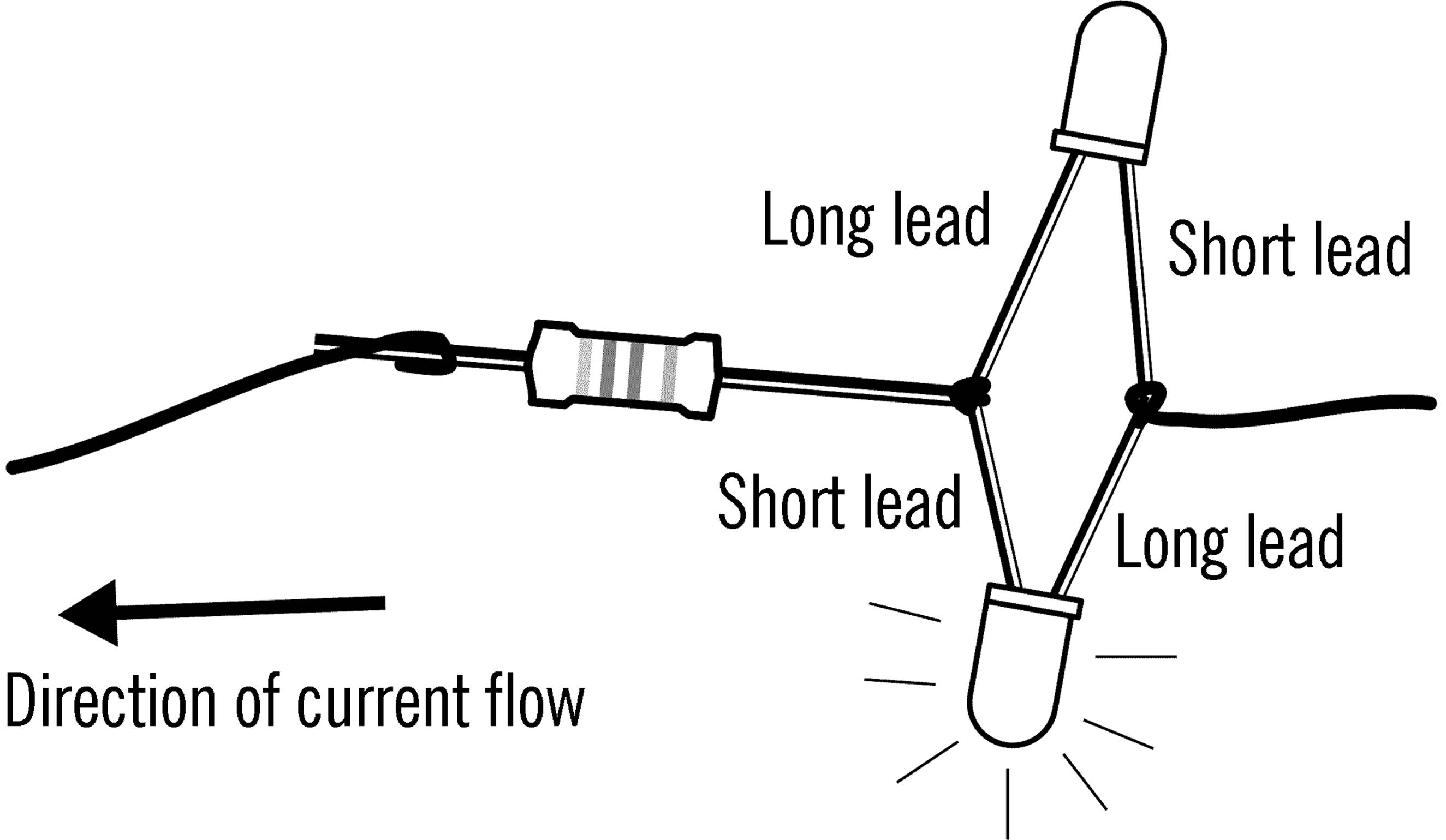
Operation of Equipment: Each LED conducts electricity in only one direction, and lights only when conducting electricity. When current is flowing in one direction, one LED lights up. When the current flows in the other direction, the other LED lights up. If the current alternates or changes directions, the two LEDs alternate, producing a blinking effect. With red LEDs and the given choice of resistor (in the range of 470 Ω), this circuit can be used to test circuits from 1.5 V–9 V AC or from 2 V–12 V DC. Using a higher voltage may damage the LEDs.
Can You Work Like a Scientist?
1. Electric current from a battery is normally described to flow from the positive pole through to the circuit and back through the negative pole into the battery. Which LED lights up when you connect the negative pole of the battery to the side of the current flow indicator with the resistor, and the positive pole to the side with the LEDs? Will a single battery cell provide enough voltage?
2. Which LED lights up when you connect the positive pole of the battery to the side of the current flow indicator with the resistor, and the negative pole to the side with the LEDs?
3. Does it affect the direction of flow of the current if you change the wires on the battery? Try a car battery.
4. Connect up the current reverser switch with the current flow indicator and the battery. What happens to the bulb when you reverse the switch? Why?
5. Connect up your power supply. What are the positive and negative poles of the direct current part of the power supply? See “AC or DC Power Supply”.
6. Connect up the current flow indicator to the AC clips on the power supply. What difference do you notice? Is there a difference if you use 3 or 6 volts?
7. Connect up the current flow indicator to a hand crank generator. What determines the number of flashes a second? Remember each blink is caused by the current changing direction.
8. Connect up your current flow indicator to the field magnet. Does the current change in the field magnet (“Test Tube Electric Motor”)? How about on the armature?
9. Why is there a minimum voltage necessary to light up the LEDs? What is that minimum voltage, and what sets that limit? Is the minimum different for other colors of LEDs?
10.Why does the current flow indicator work for a different range for AC or DC voltage?
11.What changes would be necessary in order to use the current flow indicator with household current, to see how it flickers? Could it be done with a simple change in resistor? In addition to electrical safety, you will need to find as the voltage and current that LEDs can tolerate, as well as the power dissipation in the resistor. How can these things be calculated?
Analog Computer
Purpose: An analog computer is a type of electronic brain that changes or converts numbers into something else (such as an electrical current) that can be worked easier than the numbers.44 A slide rule is an example of an analog computer since numbers have been changed to distances on the slide rule.45
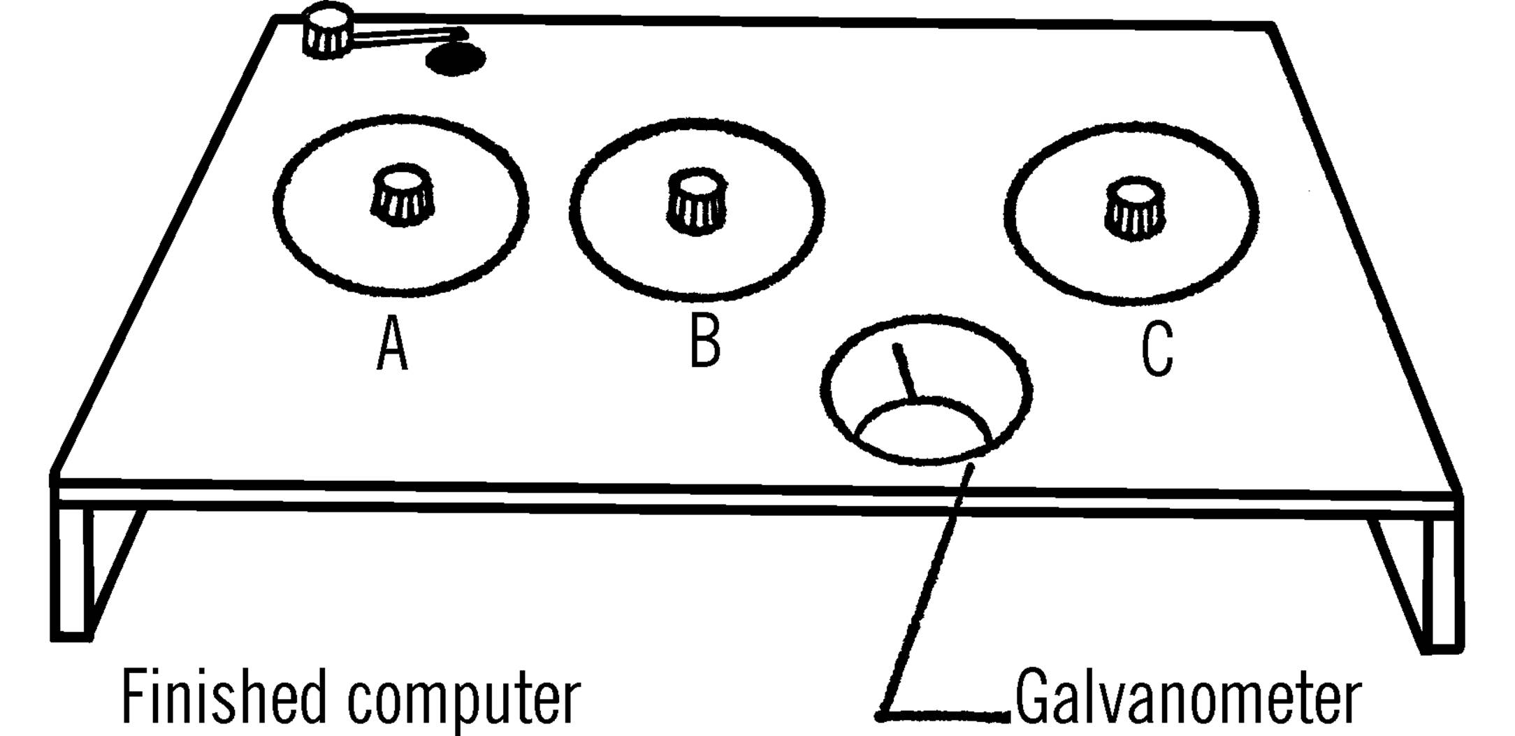
Materials: Two 50-ohm potentiometers, one 1000-ohm potentiometer, galvanometer,46 3 volt direct-current source (two 1½ volt batteries or power supply), three dial knobs, bell wire, a piece of masonite (1’ × 2’), a 2’ piece of 1” × 2” wood.
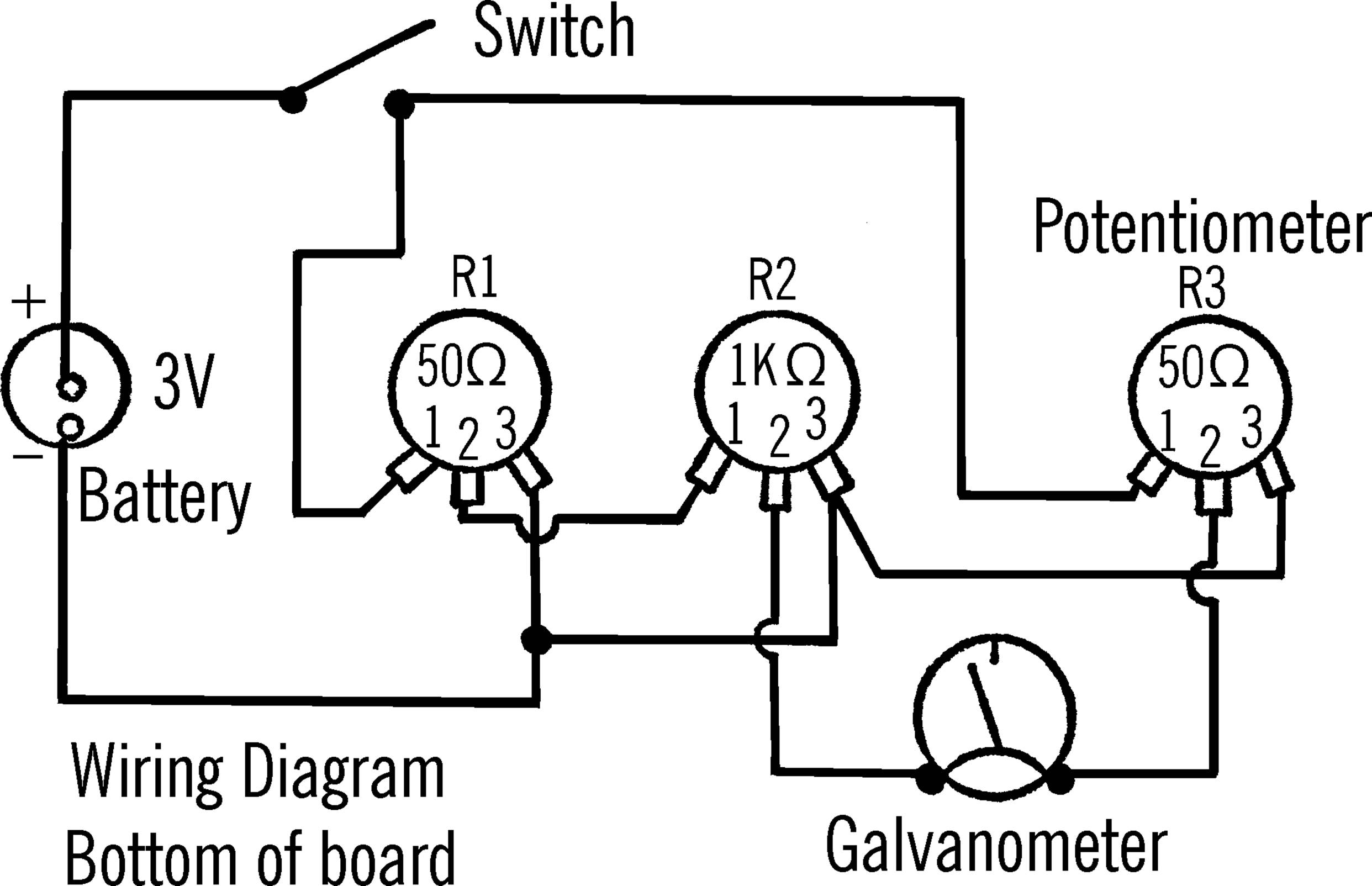
What to Do: Cut the piece of 1×2 in half and nail each piece along the end of the piece of masonite. Drill three ¼” holes in the masonite. These holes should be evenly spaced as shown. Remove the top nut off each potentiometer and slide the potentiometer through the correct hole from the bottom side. Fasten the nuts in place on the top side of the board. The middle potentiometer is the 1000-ohm size.
All of the wiring is done beneath the board. The schematic diagram is given below as well as an actual diagram of the appearance of the bottom of the board. The number 1 on the potentiometer is the side of the potentiometer from which no current will flow. No. 2 is the variable voltage controlled by turning the knob. No. 3 is the position in which the potentiometer is wide open and all possible current flows.
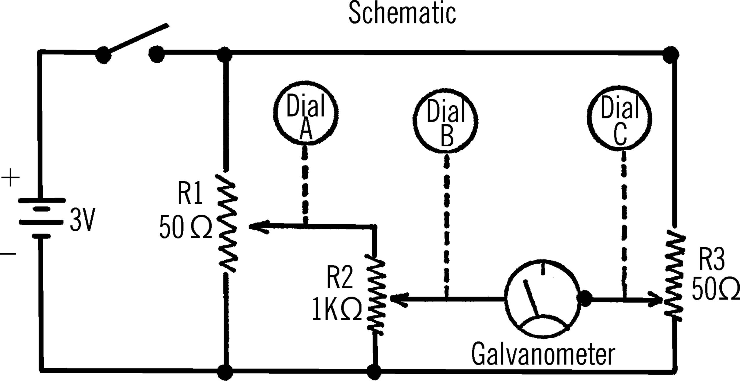
Operation of Equipment: Potentiometers R1 and R2 are wired together in such a way that an electrical current that goes through R1 also goes through R2 and then to one side of the galvanometer. If the dial on R1 is set half way, the voltage from the battery is cut in half. This voltage is sent to R2. If the setting on R2 is one-third of the dial, this voltage is cut by one-third. Thus 3 volts is cut to 1½ volts at R1. The voltage at R2 is cut to ½ volt.
R3 is connected directly to the battery and the other side of the galvanometer. When R3 is turned to such a position that the current flow through it is exactly equal to the current flow through R1 and R2, the two pushes exactly balance each other, and the galvanometer does not register any current flow. The position of the pointer connected to R3 would indicate the correct answer.47
In order to program your computer, slip cardboard discs over the stems of the potentiometers on the top side of the board. Fasten the cardboard discs with the nuts or with glue. You should cut out and glue cardboard pointers to the bottoms of the knobs. The knobs and pointers are then fastened on the stems of the potentiometers.
You can make a multiplication scale on the cardboard discs. Turn R1 half way. Label the spot the pointer indicates as 5. Turn R2 half way and label this 5. Now turn R3 so that the galvanometer indicates no current flow. Since 5 times 5 is 25 you should label the position of the R3 pointer as 25. Now turn R1 so that no current flows. Label this 0. Do the same for R2. Turn R3 so that the galvanometer indicates there is no current flow. Mark this 0. Turn both R1 and R2 wide open. Mark 10 on each dial. Turn R3 so that the galvanometer indicates no current flow. Since 10 times ten equals a hundred, label the position of the pointer of R3 one hundred. Then make your subdivisions from one to ten on both R1 and R2. Each time turn R3 and mark the answer on the dial as you did before.
Can You Work Like a Scientist?
1. If you made the dials as just described, you can multiply up through the ten tables. Can you make subdivisions between each number so that you can multiply such numbers as 3.5 times 6.8?
2. How can you multiply numbers larger than ten? Think of it this way. Three could also be thirty and 3.4 could be 34.
3. Can you divide with your computer? If you set R2 and R3, the answer should be on R1.
4. Computers can be used for many things. Can you make new dials for your computer which will help you predict weather? R1 could be labeled with air pressure readings. R2 could be labeled with the seasons of the year. R3 then would indicate the type of weather you generally would expect. When you make out your dials, you are doing what is called programing your computer. The more accurately you program your computer, the more accurate the results.
5. Can you program a computer to indicate the total number of calories you will eat in a day? One dial can list various lunches. Another dial can list various dinners. The third dial can indicate the total number of calories.
6. Can you program a computer to give automatically the correct distances between various combinations of cities?
7. Can you program a computer that will automatically give you the area for a circle of known diameter?
8. Can you program a computer so that if you know the time and distance it took to get to a certain place, the computer would give you the average speed?
9. Can you program a computer to give you the square and the square root of various numbers?
10.Can you program a computer to give you the cube and the cube root of various numbers?
11.Can you program your computer so that you can figure the distances from the Earth to different planets at various times throughout the year?
12.How can you multiply three numbers by three numbers?
13.Can you program a computer so that if the velocity of a missile and the distance to a target is known, you automatically can figure the proper angle to fire the missile?
14.Could you use a compass galvanometer instead of a commercial galvanometer for your computer? What are the limitations?
15.What effect does the amount of electricity have on the operation of the computer?
16.Could you use a voltmeter instead of a galvanometer?
17.Below is a wiring diagram using an audio signal generator and a head set instead of a galvanometer. When you do not hear a sound, the current flow is balanced. Could you make such a computer?
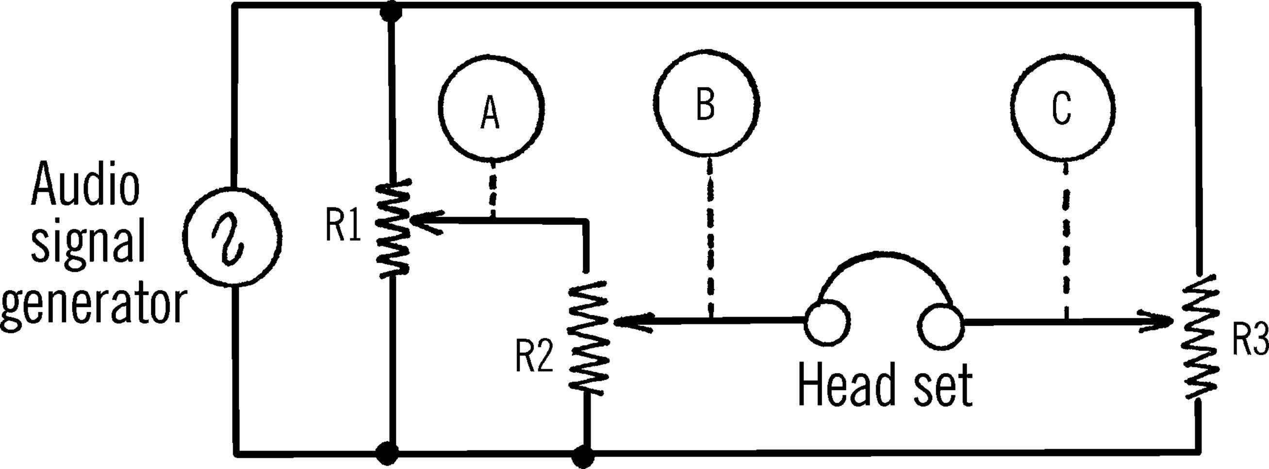
Digital Computer
Purpose: A digital computer is a type of electronic brain. It consists of involved wiring patterns. In an analog computer numbers are converted to electrical current. In the digital computer exact answers are possible because an electrical circuit has been wired that will furnish only that answer. Answers are sometimes given by certain bulbs that light up.
Materials: Masonite for dials and base, small ½” bolts and nuts, bell wire, dry cell battery or power supply, five flashlight bulbs, sockets, and washers.
What to Do: Cut out six masonite discs about six inches in diameter. Drill holes in the center of each disc. Mount the discs on the board as shown. Washers should be used as spacers between the masonite disc and the board. Drill a hole in the outer edge of the disc. Place a pencil in the hole and turn the disc. Remove the disc and drill holes every half inch around the circle drawn on the board. Insert bolts into each hole and fasten with nuts on the reverse side of the board.
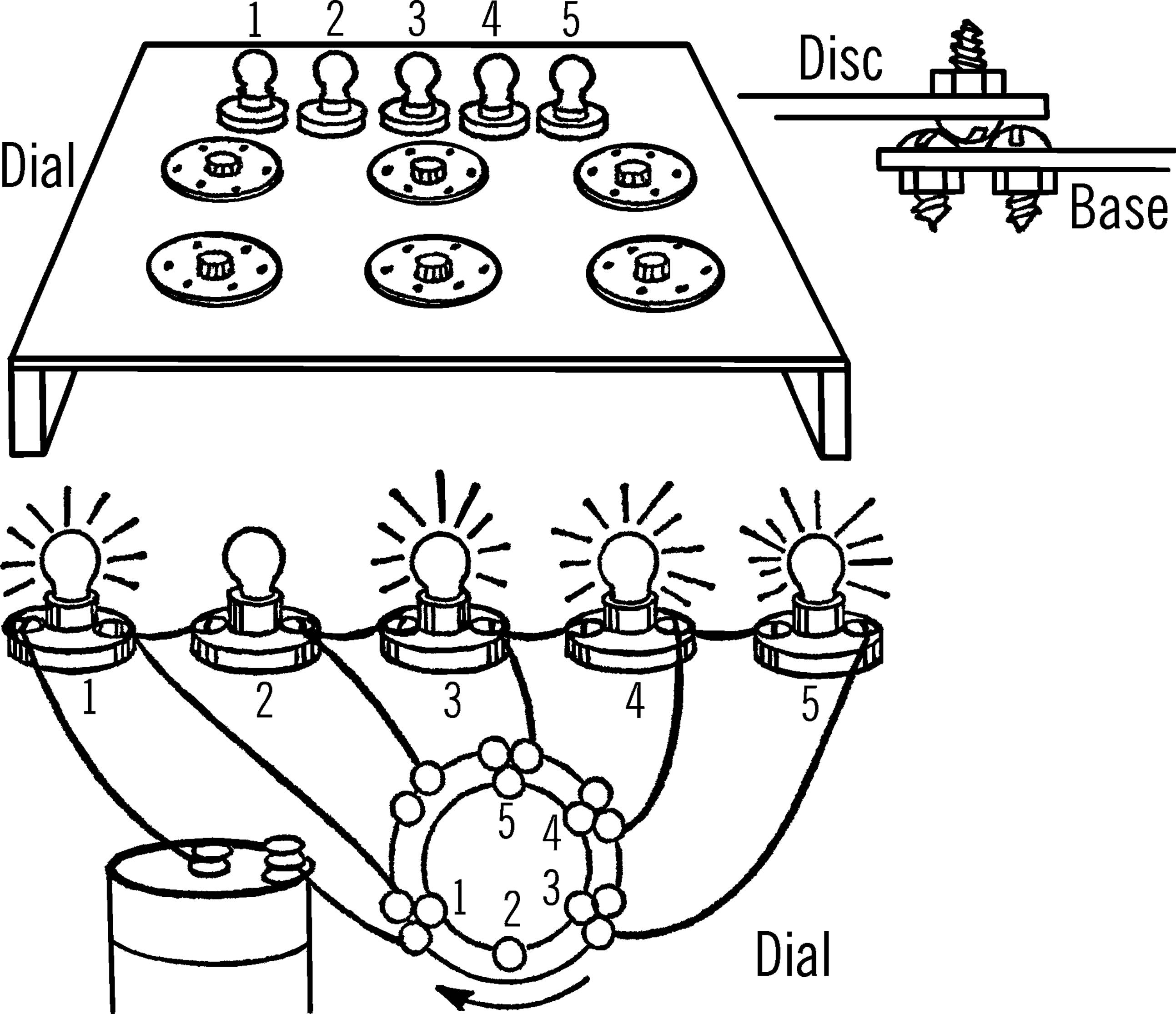
Drill other holes in the disc. Each hole should be the same distance from the center hole and a half inch apart. The necessary bolts are placed with the head of the bolt down. When the disc is rotated, the head of the bolt on the disc fits and makes firm contact with the heads of the bolts coming through the board.
A series of five flashlight bulbs should be mounted on the base in sockets. These can be connected with any number of bolts to form electrical circuits for different problems.48
Operation of Equipment: A simple circuit should give you an idea how this computer can be programed. You can then use your imagination for making other circuits.
PROBLEM 1—Can you wire a dial so that you can choose to light up any of five different bulbs? (For the sake of clarity, the heads of the bolts that would be directly under the bolt on the dial are shown alongside the dial.) Connect up the wires as shown. As you rotate the dial, bulb one will light up. Turn the dial again and bulbs one and two will light up because of the complete circuit. As you continue to turn the dial more and more bulbs will light. Can you trace the complete circuit?49
Problems to Investigate in the Study of Electricity and Magnetism
(P)-Primary
(I)-Intermediate
(U)-Upper
1. Are all magnets the same shape and size? Collect different types of magnets. (P)
2. Do magnets attract each other? (P)
3. What things do magnets attract? Will all magnets attract the same things? (P)
4. What things will magnets not attract? (P)
5. Will magnets attract things through paper? Through tin? What materials will magnetism pass through? (P)
6. Do all magnets attract things with the same amount of force? Can you measure the attracting force of different magnets? (P)
7. Does magnetism travel through the air? (P)
8. Will both ends of a magnet attract things? (P)
9. Do both ends of a magnet attract the end of another magnet? (P)
10.Does a magnet affect a compass? (P)
11.Do both ends of a magnet affect a compass in the same way? Are both ends of a compass alike? (P)
12.What end of a magnet attracts the point or arrow of the compass? Mark this end with a piece of tape and write N on the tape. (P)
13.What end of a magnet attracts the back end of the pointer or arrow? Label this S. Does the magnet act this way with all compasses? (P)
14.Mark another magnet in the same way as you did in the two problems mentioned before. Does this magnet make different compasses act in the same way as the first compass? (P)
15.If you bring the two ends of the magnets marked N together, will the magnets attract? (P)
16.If you bring the two ends of the magnets marked S together, will the magnets attract? (P)
17.Is there a force between the two N ends that seems to push the magnets away from each other? Is there a force between the two S ends that seems to push away (repel) from each other? (P)
18.Can you measure the force that pushes away or repels two like poles? (I)
19.Is this force of repulsion the same for all magnets? (I)
20.Do both north poles and both south poles push away or repel with equal force? (I)
21.If you bring the end marked N of one magnet and the S end of the other magnet near each other, do the magnets push away or attract? Try the other two ends of the magnets (marked S and N). Do they act the same way? (P)
22.Try these experiments on other magnets. Do all magnets act in a similar way? (I)
23.Will magnets pick up all kinds of metal? What kinds of metals will magnets attract? (P)
24.Will magnetism pass through metal and attract something else? Try touching a strong magnet to a nail and then picking up a pin with the nail. (P)
25.Will magnetism pass through the air and then through a piece of metal and make the metal magnetic? (I)
26.Will magnetism go through a vacuum? (I)
27.Are both ends of a magnet just as strong? Be sure to try many different magnets. (I)
28.Does the strength of the magnetic force increase or decrease as you move the magnet away from a piece of iron or steel? Can you measure and compare the strength and the distance? (I)
29.Does a magnet attract a nail? Is the nail a magnet? (P)
30.Does a nail affect a compass? Do both ends of a nail affect the compass the same way as a magnet? (P)
31.Do other pieces of iron and steel affect the compass in the same way? How about other metals? (P)
32.Is the needle or pointer of a compass magnetized? (P)
33.Will the compass needle always point in the same direction if magnets and other metal objects are not nearby? (P)
34.Will a compass point in the same direction both inside and outside a building? (P)
35.Does the compass always point in the same direction? What direction is this? (P)
36.What causes a compass to face always toward the north? (P)
37.In what directions will compasses point in different parts of the world? (I)
38.Where are the Earth’s magnetic poles? Have these poles always been in the same place throughout the history of the Earth? (U)
39.Can you magnetize a nail by rubbing it with a magnet? What ways do you rub the nail to make the strongest magnet? (P)
40.What materials are easy to magnetize? What materials are difficult to magnetize? Can you keep track of how long these materials retain their magnetism? (P)
41.Can you magnetize a piece of iron or steel by laying it near a magnet and leaving it a few days? (P)
42.Can you magnetize a piece of iron or steel by using the Earth’s magnetic poles? (I)
43.What materials around you (pipes in your home, cans on a shelf, steel beams in a building) have been magnetized? Check with a compass. (I)
44.What effect does heat have on a magnet? Magnetize a nail and then heat it in an alcohol burner.50 Test the strength on a magnetometer. (P)
45.What effect does hitting a magnet sharply have on its strength?51 (P)
46.Do magnets get weaker while they are not being used? Can you recharge a magnet? (I)
47.What can you do to keep a magnet from growing weak while you aren’t using it? (I)
48.What parts of a magnet are the strongest? What part is the weakest? Measure with a magnetometer or place a small steel ball in the center of the magnet. (P)
49.Could you make a magnet stronger by changing its shape so the strong parts of the magnet pull together? (P)
50.What shapes of magnets are used by industries? How does the shape and power of the magnet fit the particular need? (U)
51.If a compass needle is a magnet, could you make a magnet by magnetizing a needle? (P)
52.How did Columbus make a floating compass to guide his ships? (P)
53.If you make a floating magnet, should you use a glass or steel dish? (P)
54.What happens to a compass if there is a piece of iron or steel nearby? Could you offset this pull by using more iron or steel? (I)
55.How do ships offset the pull on the compass of ship parts made of iron and steel? (U)
56.What is the advantage of having magnets float in oil or other heavy liquids? (U)
57.How can you see the pattern of force given off by a magnet? Use iron filings and sprinkle over a piece of cardboard. What hypothesis have you proven or verified by observing the magnetic lines of force? (P)
58.What is the pattern of magnetic field for two magnets with their N poles placed so that they face each other? (P)
59.What is the pattern of magnetic field for two bar magnets with their S poles facing each other? (P)
60.What is the pattern of magnetic field for two bar magnets with the N pole of one magnet facing the S pole of the other magnet? (P)
61.What is the pattern of magnetic field for two bar magnets placed so they form a T? (I)
62.What is the pattern of magnetic field for two horseshoe magnets placed so that the N poles face each other and the S poles face each other? (P)
63.What is the pattern of magnetic field for two horseshoe magnets when the N pole of one magnet faces the S pole of the other magnet? (P)
64.Are there any particles in dirt that are attracted by a magnet? Can you try dirt from many areas? (I)
65.Are there any rocks that are attracted by a magnet? Do these rocks have magnetic poles? (I)
66.What effect does electric current flowing through a wire have on a compass if the wire is laid over the compass? (P)
67.Does the Earth have a magnetic field around it? Where are the poles? (I)
68.Are there lines of magnetic force surrounding the Earth? How can we map these? (U)
69.What causes the magnetic force inside the Earth? Is this force the same as gravity? (U)
70.What effect does the Earth’s magnetic field have on radio communication? (U)
71.Do other members of the Solar System have magnetic fields surrounding them? (U)
72.What effect does the Earth’s magnetic field have on energy from the sun? On energy from other sources in the universe? (U)
73.Do alternating (electricity from a house plug) and direct current (electricity from a battery) have the same effect if they flow through a wire that is placed on a compass? (I)
74.What effect has direct current on a compass needle if the wires connecting to the battery are reversed? (I)
75.If you coil wire around a compass, is the magnetic field strengthened? Can you measure the strength of this magnetic field? (I)
76.If you place a nail in this coil of wire, will it be magnetized? (I)
77.What other objects can be magnetized by being placed in a coil of wire? (I)
78.Does a magnet increase in strength if placed in a coil of wire connected to direct current? (P)
79.Does a magnet increase in strength if placed in a coil of wire connected to alternating current? (I)
80.How does increasing the strength of the current (adding more batteries) affect the strength of the electromagnet? (I)
81.How does the number of turns of wire in a coil affect the strength of an electromagnet? (P)
82.Does an electromagnet have a north and south pole? (P)
83.Does an electromagnet have the same effect on a compass as a regular magnet? (P)
84.What materials in a coil retain their magnetism after the current has been turned off? How long do they retain their magnetism?
85.Is it better to use alternating or direct current in an electromagnet? (I)
86.What uses are made of electromagnets in industry? Can you experiment with some of these uses? (U)
87.What effect has different kinds of wire in the coil on the strength of an electromagnet? (I)
88.Can a piece of iron or steel always be made a stronger electromagnet by increasing the number of coils or the strength of current? What limits the strength of an electromagnet? (U)
89.How strong can you make a magnet by rubbing a nail or piece of steel with another magnet? Can you increase the strength by rubbing the object longer? (I)
90.Does an object increase in magnetic strength if it is left in the Earth’s magnetic field for a long period of time? What is the limit of the strength of an object magnetized in this manner? (U)
91.Can you make a magnet by magnetizing bits of iron filings in a tube? Does each piece of iron filing act like a magnet? (I)
92.If a magnet is broken, is each piece as strong as the original magnet? (I)
93.If a magnet is broken, do both pieces still have north and south poles? (P)
94.Why does steel retain its magnetism longer than objects made of iron? (U)
95.Are magnets made of iron, nickel, and cobalt stronger than magnets made of steel? Why? (U)
96.Can you experiment with various types of iron, steel, and alloys to determine the ease of magnetism and the ability of each to retain its magnetism? (U)
97.How is a magnet used in a telephone? In a telegraph? In a doorbell? (I)
98.How are magnets used in engines? Radios? Television? (U)
99.Does the ground contain bits of iron? Try using a strong magnet on different kinds of soil. (I)
100. Can you use a magnet to separate various mixtures? Try mixing filings with different materials. (P)
101. Can you detect the magnetic field around a wire by using iron filings? Run a wire through a piece of cardboard. Connect the wire to a dry cell battery. Sprinkle iron filings on the cardboard near the wire and then tap the cardboard. (I)
102. If an electric current can be used to make a magnet, can a magnet be used to make an electric current? Attach a coil of wire to a galvanometer. Move a magnet in and out of the coil of wire. (I)
103. Is it the magnet that generates the current, or is it the magnet breaking the lines of force around the coil of wire? (I)
104. Will materials that are not magnetized help generate a current in a coil? (U)
105. What kind of current is generated by moving a magnet back and forth through a coil? (U)
106. What effect is the rate of moving the magnet back and forth through the magnetic field having on the amount of current produced? (I)
107. Can a current be produced in a coil if the coil is revolved around a permanent magnet? (I)
108. What effect does the size of the coil have on the amount of current produced? (U)
109. What effect has the strength of the magnet in the coil on the amount of current produced? (U)
110. Can you make alternating and direct current generators? What is the difference between the two? (I)
111. How does the voltage vary in an alternating generator? What is the effect of frequency (number of complete turns of the coil over the permanent magnet) on the amount of current produced? (U)
112. What frequency is necessary in order to avoid flickering when alternating current is used for lighting? (U)
113. What is the difference between a generator and an electric motor? Can you make a generator and measure the output? Try various experiments to improve the performance. (U)
114. Through what kind of wire will electricity flow? (P)
115. What kind of wire is the best conductor of electricity? (I)
116. Does electricity need a complete path? Why doesn’t electricity flow if there is a break in the wire? (P)
117. Can you make a switch in order to control the flow of electricity? (P)
118. What materials will conduct electricity? What materials will not? (P)
119. Can you measure the conductivity of different materials? (I)
120. What materials resist the flow of electricity? Can you measure the resistance of various materials? (I)
121. What effect has the size of the wire on the resistance to the flow of electricity? What effect has the length of the wire on the flow? (U)
122. How is resistance to electrical flow used to produce heat and light? Can you measure the amount of heat and light given off by various resistors? (I)
123. How do different kinds of switches make a complete path? Examine knife switches, flashlights, house light switches, outlet plugs, starter buttons, doorbells, mercury switches. (P)
124. Is there electricity that is not made by man? What is electricity? (P)
125. Do different materials contain electricity? Rub a balloon on some wool. Hold the balloon over the hair on your head. Is this electricity? (P)
126. Does paper contain electricity? Rub a sheet of newspaper with a ruler while holding the sheet of newspaper against a smooth surface. How do you know electricity affects the paper? Can you see a spark? (P)
127. Does wool contain static electricity? Place a piece of wool (such as a wool blanket or shirt) in a clothes dryer. Turn the dryer on and leave the wool in until the material is very warm and dry. Is the wool charged with static (electricity at rest) electricity? (P)
128. What causes static electricity? Try rubbing wool, silk, nylon, rubber. Do these materials become charged? Try other experiments with these materials, such as heating, cooling, hitting, etc. What causes the static electricity charge? (P)
129. How do you create a static electricity charge when you walk across a rug and then touch a doorknob? (P)
130. What causes a static electricity charge when you reach for the door handle of the car from inside the car? (I)
131. What causes dust to collect on a phonograph record? (U)
132. Does dust have a positive or negative charge? How about the phonograph record? (U)
133. What materials can be charged with static electricity? What materials do not become charged? (P)
134. Will material that can be charged also be affected by a magnet? (P)
135. Are all static electricity charges alike? Charge different materials. Bring different combinations together. Are materials charged with static electricity always attracted to each other? (P)
136. What charged materials seem to attract each other? What charged materials seem to push away (repel) each other? (P)
137. Are materials that are charged in the same way attracted or repelled by each other? Charge two pieces of Saran Wrap by rubbing with your hand. Are the pieces of Saran Wrap attracted or repelled? (P)
138. Are all static electricity charges alike? Make an electroscope and record whether the leaves are attracted or repelled. (I)
139. Do like charges (two materials charged in the same way and affecting an electroscope in the same way) attract or repel? How about unlike charges? (I)
140. Does static electricity affect a compass? (P)
141. Is static electricity affected by a magnet? (P)
142. Is static electricity affected by the humidity of the air? (P)
143. Is static electricity affected by temperature? (P)
144. Can static electricity be made to jump through the air? Use an electrophorus, Van de Graaff generator, or charge wool and then observe it in a darkened room. (P)
145. Can you measure the strength of static electricity you generate? (U)
146. What affects the length of time a material will retain its static electricity charge? (I)
147. Is lightning the same as static electricity? What conditions cause lightning? (P)
148. Can you predict a lightning storm? (U)
149. Will static electricity flow through a wire? Use a Van de Graaff generator or some other generator of static electricity. (U)
150. Can static electricity be stored? Use a Leyden jar. (I)
151. What materials will conduct a static electricity charge? Try discharging a Leyden jar or Van de Graaff through different materials.52 (I)
152. What materials are non-conductors of static electricity? (I)
153. How fast does static electricity travel through different materials? Through gases? (U)
154. In what ways is static electricity useful? (P)
155. Is static electricity harmful? What has man done to eliminate or control hazards from static electricity? (P)
156. What objects will store static electricity? (I)
157. What is a capacitor or condenser? Can you experiment with making different kinds of condensers and measuring the charges stored by them? (U)
158. Can you experiment with different materials for lightning rods? Be sure you use a safe source of static electricity and not lightning to test your theories. (U)
159. What is a battery? Can you make a simple battery out of a lemon, copper wire, and a steel knife? Make fruit batteries using different fruits and metals. Can you measure the current flow in each? The current will operate a headphone. (I)
160. How does a flashlight battery work? Can you make your own? (I)
161. How does an automobile storage battery work? Can you make one? Be sure to experiment with different materials and electrolytes. (U)
162. Is the electricity from a battery the same as the electricity from a generator? Be sure to do many of the experiments mentioned with both. (P)
163. Will water conduct electricity? (P)
164. What materials added to water will make water a better conductor? Try salt, baking soda, sugar, etc. Be sure to measure the current flow of each. (I)
165. What gases are given off when current from a battery is sent through water? (I)
166. What happens when you reverse the wires on the battery? Which pole gives off hydrogen? Remember, water is made of two atoms of hydrogen to every atom of oxygen. (I)
167. How is electroplating done? Can you do various types of electroplating? (I)
168. What effect does the strength of the electric current have on the amount of metal deposited by electrolysis? (I)
169. What effect does the length of time the current flows have on the amount of metal deposited during electrolysis? (I)
170. What determines the voltage of a battery? What determines the amperage or current flow of a battery? (U)
171. Can you detect changes in heat energy produced by various amounts of voltage and current? Measure the temperature change by using a coil of wire in a container of water. (I)
172. What effect does temperature have on the conductivity of various metals? (U)
173. How is a fuse used to protect against too much current flow? Can you make different types of fuses and determine the electrical load they will carry? (P)
174. How does a circuit breaker work? What determines the danger level for different circuits? (U)
175. What is the difference between an alternating and direct current motor? Can you build an example of each? (I)
176. How does a voltmeter work? Can you build a voltmeter and use it to measure the voltage in various circuits? (U)
177. How does an ammeter work? Can you build an ammeter and measure the amount of current in various circuits? (U)
178. How does an electric clock keep time? How is the voltage regulated by power companies? (U)
179. Can the magnetic field around one wire induce or start a current in another wire? Try both alternating and direct current. (I)
180. What is a transformer? Can you make a transformer by placing an electromagnet inside a coil of wire? (I)
181. How does the number of turns of wire around the iron core in the primary (the wire with the current flowing through) affect the voltage of the outside coil of wire in which the current is induced (secondary)? (U)
182. How does the size of wire used in the primary and secondary affect the voltage? (U)
183. Can you devise transformers for different voltage uses? (U)
184. What is a step-up transformer? What is a set-down transformer? (U)
185. How does an induction coil enable direct current to be stepped up? Can you experiment by making and breaking the direct current in the primary? Is there a current induced in the secondary? (U)
186. How does a light bulb work? Can you experiment with different kinds of materials as the filament? (I)
187. Can you make a light bulb that won’t burn out? Compare your light bulb with standard commercial light bulbs. Record the life and brightness of each. (U)
188. What gases under low pressure conduct electricity? How is this the basis for neon lights? Can you experiment with the pressure as compared to the brightness? (U)
189. What colors do various gases give off when an electrical current is passed through the gas at low pressure? (U)
190. How does a fluorescent light work? How can invisible ultraviolet rays give off visible light? (U)
191. Can you make a carbon arc light? How much light is given off? Can you measure the heat at the point of contact of the two carbon rods? (U)
192. Can you devise a carbon arc projector? A carbon arc searchlight? Remember to use a good mirror to collect and focus your light. (U)
193. Can you collect and focus the light from a carbon arc projector through a lens onto a piece of wood? Does focusing the rays increase the temperature? (U)
194. How does a carbon arc furnace work? Can you make one and carry on experiments with different metals? Can you determine the melting points of various metals and alloys? (U)
195. What is the difference between lights wired in series and those wired in parallel? Can you measure the voltage and amperage at various points in the circuit? (I)
196. What is the effect on the voltage if additional lights are added in series? (I)
197. How is electrical current changed from alternating to direct current? How does a rectifier work? Can you build a rectifier? (U)
198. How does a burglar alarm work? Can you devise a burglar alarm? (I)
199. How do two-and three-way switches work? Can you devise a wiring circuit that can do many things? (I)
200. What is a digital computer? Can you make a digital computer that can do certain tasks? Be sure to use the computer after you make it. (U)
201. Can you make an analog computer? Can you calibrate your computer for a particular purpose? For instance, can you design the computer to show the area of a circle when the radius is known? (U)
202. Can you use the heating effect of an electric current to measure electricity? Send an electric current through a cold iron wire. Note the sag in the wire as it gets hotter. Is the amount of sag related to the strength of the current? (U)
203. What effect do the material, length, cross-sectional area, and temperature have on the resistance of a wire? Set up an experiment using different kinds of wire. Keep the voltage constant. You can measure the amperes or amount of current. From the voltage and amperage you can determine the resistance. (U)
204. How do fuses protect against an overload of current? (P)
205. Can you make a wheatstone bridge in order to determine the resistance of various materials? (U)
206. How does an induction coil work? Can you measure the amount of voltage at the spark gap? (U)
207. What are eddy currents? Can you demonstrate the uses of eddy currents by making a repulsion coil? Try experiments to see if you can measure these currents. (U)
208. Can you magnetize needles by building up a static electricity charge in a Leyden jar and then discharging the current through a coil containing a needle? (U)
209. Can you use alternating current in the electrolysis of water? Can you use static electricity in the electrolysis of water? (U)
210. Will a magnet have any effect on an electric current flowing through a wire? Stretch a size No. 24 wire about 6 feet long between two insulated supports. Connect the wire to an alternating current supply.53 Use a rheostat to vary the current. Bring one end of a strong bar magnet near the wire while the current is flowing. (U)
211. Can you design and build a Tesla coil? Can you develop a practical use for such an instrument? (U)
212. Can you build different kinds of radio sets? Be sure to trace the principles behind radio and show how they apply to your work. (I)
213. Can you devise different kinds of television antennas? Try these out with your TV set. Be sure to test your own designs instead of copying those already on the market. (I)
214. Can you experiment with TV reception problems in your area? (U)
215. Can you devise a new use for a photoelectric cell? (U)
216. Can you experiment with different kinds of condensers? You should measure the charge that is stored. (U)
217. What effect has static electricity on plant growth? (I)
218. What effect has DC and AC current on plant growth? (I)
219. What are the problems of tuning in radios? Can you devise your own tuner? (I)
220. How does a speaker on a radio or television set operate? Can you design and make your own? (U)
221. Can you design and build a computer that can forecast weather from data you feed it? This might be either a digital or analog computer. (U)
222. Can you design and build a computer (analog) for learning the multiplication tables? Be sure to calibrate your instrument experimentally. (I)
223. What is the difference between AM and FM radio broadcasting? Can you devise a means of modulating radio carrier current so loudspeakers can respond to it? (U)
224. How fast do radio waves travel? Can you measure the velocity, frequency, and wave lengths of radio waves you generate? (U)
225. What are rectifiers? Can you experiment with using different kinds of rectifiers in place of diode and triode tubes?54 (U)
226. How does the sound track on a movie film work? Can you devise a means to put a sound track on film? (U)
227. Can you devise a means to put a sound track on film strips? (U)
228. Can you design and build your own oscilloscope? (U)
229. What are the problems of color television? Can you devise your own method of solving some of these problems? (U)
1 A neodymium (NdFeB) magnet is ideal.
2 While the spring from an old mechanical wristwatch can be used, there are many other sources. Try straightening a paper clip or the spring from a ballpoint pen. What materials work best?
3 “Hotel containers” in this context refers to a kind of fancy ashtray (once common in hotel lobbies) that would be filled with sand. Kosher salt is a good substitute.
4 The source of current shown is a No. 6 dry cell, 1.5 V. See Note 30 in Appendix E.
5 E.g., part of the ribbon from an old audio cassette tape.
6 See Note 31 in Appendix E for notes on this project, including a low-voltage alternative with LEDs.
7 Exercise extreme caution because mains voltage is involved and exposed.
8 Mimeograph stencils are now rare, but plastic surfaces are everywhere! What kinds of plastic generate stronger charges? Can you identify them by manufacturing marks or a recycling number?
9 The chain is intended to make an electrical connection between the rod and the foil on the inside bottom of the jar.
10 That is, “regular” electricity as opposed to static electricity. Exploring AC current is interesting, but can you think of reasons that you shouldn’t connect the Leyden jar directly to household (line) voltage?
11 Original text: “This is a condenser,” where “condenser” is an old name for capacitors that has largely fallen out of favor.
12 How does this method compare to magnetizing an object with a bar magnet? How about a rare-earth (neodymium) magnet?
13 Simple battery chargers may work well. However, smarter devices (like smartphone chargers) could be damaged if you connect them this way.
14 One of several galvanoscopes described starting in “Galvanoscope”.
15 See Appendix A for additional sources.
16 Use a pre-1982 penny, if possible. Newer pennies only have a thin coating of copper.
17 It is better to start with clean acid. See Note 16 in Appendix E.
18 This should be enough to light a small incandescent bulb. Can it light an LED or a neon bulb? Why or why not?
19 The output of a low-voltage ac transformer (“wall-wart”) is appropriate; do not use wall power directly.
20 Or lantern battery.
21 Electric bells were once common, as doorbells, buzzers, and alarms. See “Doorbell” about how to build one.
22 Your drugstore won’t sell you mercury any more. Note 32 in Appendix E presents alternatives for this project.
23 Switches like these are reliable and easy to make. Large paper clips may also be used instead of safety pins.
24 Use a pencil made from real wood so that it will split as indicated. Pencil grades B, HB, H, and 2H are equivalent to grades #1, 2, 3, and 4, respectively.
25 What would you have to change, in order to build a newer equivalent that uses an LED instead of a light bulb?
26 That is to say, pieces cut from a tin can. Other metals will work just as well.
27 Original wording: “…as a transformer….” See Note 33 in Appendix E about the distinction between the two.
28 Please see Note 34 and Note 35 in Appendix E for specific transformer and rectifier recommendations.
29 The rectifier bridge shown in the illustration is an old-school selenium rectifier. A suitable modern replacement is the GBU8D rectifier bridge. These instructions have been adapted for that type. See Note 35 in Appendix E for more information.
30 On a modern rectifier bridge, use the output terminal marked with a “+”.
31 There is never “no danger” when there is exposed wiring at mains voltage level, so make sure none is exposed.
32 This project was originally titled “Power Supply Transformer.” See Note 33 in Appendix E for further discussion.
33 Cover any exposed screws with electrical tape.
34 Keep in mind that even a “small” shock can still be dangerous.
35 A specific type of battery is needed. Please see Note 12 in Appendix E.
36 Carbon rods can also be purchased; see Appendix A.
37 Specifically, two-conductor insulated lamp cord that can be pulled apart.
38 Why should it crack? Remember that hydrogen gas explodes. Use a long match, safety glasses, common sense, and caution. Read Note 3 in Appendix E about safety around fire.
39 Insulated wire, ideally solid-core. Cotton insulation is not necessary; most modern plastic insulation is perfectly fine for this application. Commercially made motors always use magnet wire, a specific type of insulated wire with a very thin coat of transparent and shiny insulating varnish (usually red, yellow, or brown in color). If you have access to magnet wire, you’ll probably need to mechanically scrape the insulation off of the ends with a blade or file in order to make an electrical connection to it.
40 You may also be able to do it yourself, if you have access to a drill press and suitable vise.
41 Perhaps a more humane use is as an actual doorbell, or alarm bell.
42 Hacksaw blades are normally painted. You may need to scrape away the paint in the area where you wish to make an electrical connection.
43 This project has been updated to use modern components, and the original project has been moved to the appendix. Please see Note 36 in Appendix E for more information.
44 This particular analog computer is modeled after commercially available analog computers of the 1960s, such as the Calculo Analog Computer.
45 What modern examples of analog computers can you think of?And, if you’ve never used a slide rule, it’s worth trying out, to understand the principle of operation. You can find online simulators (and even mobile apps) to let you try one out, as well as download-and-print patterns to make a paper slide rule.
46 Either a digital ammeter or multimeter in DC current mode will work fine.
47 How does this work? Can you use Ohm’s law together with Kirchhoff’s rules to understand exactly what is going on?
48 Could you build a “modern” version of this, using LEDs instead of light bulbs? How small could you make it?
49 Are you wondering how to get from here all the way to something that you might recognize as a computer? Read Note 37 in Appendix E.
50 Only try this with a magnet that is made of steel or iron, not a plastic or rubber-coated magnet, nor rare earth or ceramic magnets.
51 Rare earth and ceramic magnets will shatter; if you decide to try this, do it with a different kind of magnet.
52 See “Modern Safety Practice” about safety practice around Leyden jars. Read up on safety about Van de Graaff generators separately before using one.
53 A low voltage ac supply.
54 Experiment with different kinds of diodes. What are (were) diode and triode tubes?