Process Technology: An Introduction - Haan A.B. 2015
3 Principles of chemical reaction engineering
3.6 Basic design equations for model reactors
3.6.1 Material balances
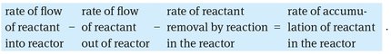
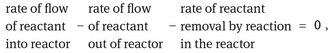
The starting point for any reactor calculation is the material balance that uses the principle of conservation of matter to derive the basic design equations. Fig. 3.6 illustrates that the basic form of the material balance for a reactor has to take into account four contributions:
![]()
(3.29)
or,
(3.30)
When the composition within the reactor is uniform (independent of position), the accounting may be made over the whole reactor. Where this is not the case, it must be made over a differential element of volume and then integrated across the whole reactor. For the various reactor types this general mass balance equation simplifies one way or another, and the resulting expression gives the basic performance equation for that type of unit. For example the first two terms are zero in a batch reactor, and the accumulation term disappears in a steady-state flow reactor.
3.6.2 The ideal batch reactor
In a batch reactor the feed material is treated as a whole for a fixed period of time. This is schematically shown in Fig. 3.7. In most cases the batch reactor is assumed to behave ideally, meaning that the contents are considered to be perfectly mixed. Under this condition the compositions are uniform throughout the reactor at any instant of time, and the mass balance can be made over the whole reactor. Noting that no fluid enters or leaves the reaction mixture during reaction, the general material balance reduces to
![]()
(3.31)
or
![]()
(3.32)
Fig. 3.7: Scheme of an Ideal stirred batch reactor.
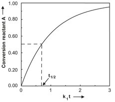
Fig. 3.8: Conversion of a first-order batch reaction versus time.
For a first-order constant density reaction of reactant A into product P the following material balance equation is obtained:
![]()
(3.33)
Integration over the period of the reaction provides us with the relation between reaction time and reactant concentration:
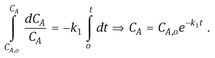
(3.34)
Introducing this time-dependent concentration in eq. (3.14) provides us with the equation for the conversion in an ideal batch reactor in the case of a first-order reaction:
![]()
(3.35)
The dependence of the conversion on the reaction time is illustrated graphically in Fig. 3.8 for a first-order reaction. The reaction time τ needed for a certain concentration decrease of reactant A can be obtained by rearranging eq. (3.34):
![]()
(3.36)
A characteristic value for a batch reaction is the time required to reduce the concentration of reactant A to half its original value. This characteristic time is called the half-value time and is obtained by introducing ![]() :
:
![]()
(3.37)
Half-value times are of special importance for the characterization of the decomposition behavior of peroxides used as initiators in many radical polymerization processes. Because peroxide decomposition is a very exothermic reaction, it is absolutely essential to minimize the spontaneous decomposition of the peroxide during storage. This is done by carefully controlling the temperature during storage, exploiting the strong temperature sensitivity of the decomposition reaction.
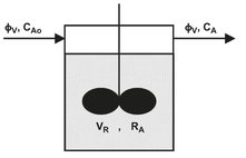
Fig. 3.9: Schematic representation of an continuous ideal stirred tank reactor (CISTR).
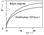
Fig. 3.10: Comparison of conversion for a first-order reaction in an ideal batch and ideal continuous stirred tank reactor.
3.6.3 The continuous ideal stirred tank reactor (CISTR)
In a continuous ideal stirred tank reactor, reactants and products are continuously added and withdrawn from the reactor vessel. The term ideal reflects the assumption that the reactants are diluted immediately upon entering, and the composition is considered uniform throughout the reactor. As a result, the exit stream from the reactor has the same composition as the fluid within the reactor. Fig. 3.9 illustrates that when the mass of withdrawn product mixture equals the mass of supplied reactants the reaction volume remains constant, and the reactor is said to operate in a steady state. In that case the mass balance over the CISTR becomes
![]()
(3.38)
or
(3.39)
resulting in the following general form for the mass balance over reactant A:
![]()
(3.40)
which, for a first-order constant density reaction of reactant A into product P, becomes
![]()
(3.41)
The average residence time τ is defined as the time that is needed to fill the reactor volume VR with volume rate φV, or in other words,
![]()
(3.42)
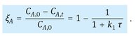
Rewriting eq. (3.41) provides us with the relations describing the concentration and conversion of reactant A as a function of the average residence time:
![]()
(3.43)
(3.44)
This conversion is compared with the conversion of an ideal batch reactor in Fig. 3.10. It can be seen that the volume of a continuous ideal stirred tank reactor must always be larger to achieve the same conversion. This is due to the lower reactant concentrations caused by the continuous perfectly mixed operation.
3.6.4 Ideal continuous tubular reactor
The tubular reactor is a vessel through which flow is continuous, usually at steady state, and configured so that conversion and other dependent variables are functions of the position within the reactor rather than of time. In an ideal tubular reactor, the reaction mixture passes through in a state of plug flow, which, as the name suggests, means that the fluid moves like a solid plug or a piston. Furthermore, it is assumed that the fluid properties, temperature, pressure, and composition are also uniform across the section normal to the fluid motion. Of course the compositions, and possibly also the temperature and pressure, change between inlet and outlet of the reactor in a longitudinal direction. The basic design equation for an ideal tubular is obtained by applying the general mass balance over a differential element of volume δV, as illustrated by Fig. 3.11. Under steady-state conditions, the accumulation term is zero, and the mass balance for a differential reactor element over reactant A yields
![]()
(3.45)
or
![]()
(3.46)
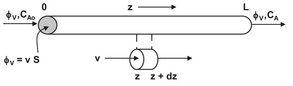
Fig. 3.11: Schematic representation of a differential element of a tubular reactor.
Introduction of the tubular reactor axial surface area S results in φv, = vS and dVR = S dz, where v stands for the longitudinal velocity (m/s). For a first-order constant density reaction of reactant A into product P,
![]()
(3.47)
giving
![]()
(3.48)
which can be integrated over the length of the reactor L to give the concentration profile of reactant A over the length of the tubular reactor:
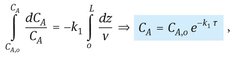
(3.49)
where τ(= L/v) is the residence time in the tubular reactor. Note that this result is identical to the conversion profile obtained for the ideal batch reactor, which leads us to the general conclusion that the ideal continuous tubular reactor behaves identically to the ideal batch reactor. This is schematically depicted in Fig. 3.12, because a tubular reactor can be considered to consist of a series of infinitely small ideal batch reactors which remain in the reactor for a residence time τ(= L/v).
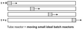
Fig. 3.12: Representation of a tubular reactor by a series of infinitely small ideal batch reactors.
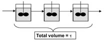
Fig. 3.13: Cascade of ideal stirred tank reactors with equal total volume V.
3.6.5 Cascade of continuous ideal stirred tanks reactors
Higher conversions of reactants with stirred tanks can be obtained by using several of them with an equal total volume in series. From Fig. 3.13 it can be seen that the product stream from the first reactor is the feed for the second one. When each reactor has the same volume, the concentration and conversion of reactant A for a series of N reactors can be calculated from
![]()
(3.50)
and
![]()
(3.51)
When the number of reactors in series is increased and the total volume is kept constant, the characteristics of a tubular reactor are approached. This is schematically depicted in Fig. 3.14.
![]()
Fig. 3.14: Representation of tubular reactor characteristics by a large number of continuous ideal stirred tanks (CISTR).