Process Technology: An Introduction - Haan A.B. 2015
6 Evaporative separations
6.2 Multistage distillation
6.2.1 Distillation cascades
Flash distillation is a very simple unit operation that in most cases produces only a limited amount of separation. Increased separation is possible in a cascade of flash separators that produces one pure vapor and one pure liquid product. Within the cascade the intermediate product streams are used as additional feeds. The liquid streams are returned to the previous flash drum, while the produced vapor streams are forwarded to the next flash chamber. Fig. 6.8 shows the resulting countercurrent cascade, so called because vapor and liquid streams go in opposite directions. The advantages of this cascade are that there are no intermediate products and the two end products can both be pure and obtained in high yield.
Although a significant advance, this multiple flash drum system is seldom used industrially. Operation and design is easier if part of the top vapor stream is condensed and returned to the first stage, reflux, and if part of the bottom liquid stream is evaporated and returned to the bottom stage, boilup. This allows control of the internal liquid and vapor flow rates at any desired level by applying all of the heat required for the distillation to the bottom reboiler and do all the required cooling in the top condenser. Partial condensation of intermediate vapor streams and partial vaporization of liquid streams is achieved by heat exchange between all pairs of passing streams. This is most effectively achieved by building the entire system in a column instead of the series of individual stages, as shown in Fig. 6.8. Intermediate heat exchange is the most efficient with the liquid and vapor in direct contact. The final result is a much simpler and cheaper device, the distillation column shown in Fig. 6.9.
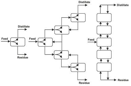
Fig. 6.8: Flash drum cascades.
6.2.2 Column distillation
Most commercial distillations involve some form of multiple staging in order to obtain better separation than is possible by single vaporization and condensation. It is the most widely used industrial method of separating liquid mixtures in the chemical process industry. As shown in Fig. 6.9, most multistage distillations are continuously operated column-type processes separating components of a liquid mixture according to their different boiling points in a more volatile distillate and a less volatile bottoms or residue. The feed enters the column at the equilibrium feed stage. Vapor and liquid phases flow counter currently within the mass transfer zone of the column where trays or packings are used to maximize interfacial contact between the phases. The section of column above the feed is called the rectification section and the section below the feed is referred to as the stripping section. Although Fig. 6.9 shows a distillation column equipped with only 12 sieve trays, industrial columns may contain more than 100. The liquid from a tray flows through a downcomer to the tray below, and vapor flows upward through the holes in the sieve tray to the tray above. Intimate contact between the vapor and liquid phases is created as the vapor passes through the holes in the sieve tray and bubbles through the pool of liquid residing on the tray. The vapors moving up the column from equilibrium stage to equilibrium stage are increasingly enriched in the more volatile components. Similarly, the concentration of the least volatile components increases in the liquid from each tray going downward.
The overhead vapor from the column is condensed to obtain a distillate product. The liquid distillate from the condenser is divided into two streams. Part of is withdrawn as overhead product (D), while the remaining distillate is refluxed to the top tray to enrich the vapors. The reflux ratio is defined as the ratio of the reflux rate to the rate of product removal. The required heat for evaporation is added at the base of the column in a reboiler, where the bottom tray liquid is heated and partially vaporized to provide the vapor for the stripping section. Plant-size distillation columns usually employ external steam powered kettle or vertical thermosyphon type heat exchangers (Fig. 6.10). Both can provide the amount of heat transfer surface required for large installations. Thermosyphon reboilers are favored when the bottom product contains thermally sensitive compounds, and only a small temperature difference is available for heat transfer and heavy fouling occurs. The vapor from the reboiler is sent back to the bottom tray, and the remaining liquid is removed as the bottom product.
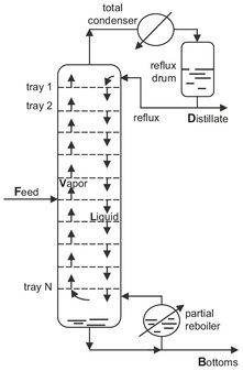
Fig. 6.9: Sieve plate distillation column.
6.2.3 Feasible distillation conditions
Industrial distillation processes are restricted by operability of the units, economic conditions, and environmental constraints. An upper limit exists for feasible operating temperatures. One reason is the thermal stability of the species in the mixtures to be separated. Many substances decompose at higher temperatures, and some species are not even stable at their normal boiling points. A second reason for a maximum temperature limitation is the means of heat supply. In most cases the required energy is supplied by condensing steam. The pressure of the available steam places an upper limit on temperature levels that can be achieved. Only in special cases (crude oil, sulfuric acid), higher temperatures may be realized by heating with hot oil or natural gas burners. With high-pressure steam the maximum attainable temperatures are limited to 300 °C, which can be raised to temperatures as high as 400 °C when other media are used. The temperature of the coolant for the overhead condenser dictates the lower limit of feasible temperatures in distillation columns. In most cases water is used, resulting to a minimum temperature in the column of 40—50 °C.
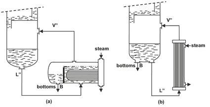
Fig. 6.10: Industrial reboilers: (a) kettle-type; (b) vertical thermosyphon-type.
In most cases temperature constraints can be met by selecting a proper operating pressure. Operating temperatures can be decreased by the use of a vacuum. It is technically feasible to operate distillation columns at pressures down to 2mbar. Lower pressures are seldom used because of the high operating and capital costs of the vacuum-producing equipment. A column can be operated at higher pressure to increase the boiling point of low boiling mixtures. The upper limit for the operating pressure lies in the range of the critical pressures of the constituents. In addition to temperature and pressure the feasible number of stages in industrial columns is also limited. Only in exceptional cases commercial distillation columns are constructed that contain more than 100 stages.
6.2.4 Basic design calculations
The separation of a feed F into a distillate product D and bottoms product B can be described by a mass balance over the entire column:
![]()
(6.14)
in combination with a component i balance over the entire column:
![]()
(6.15)
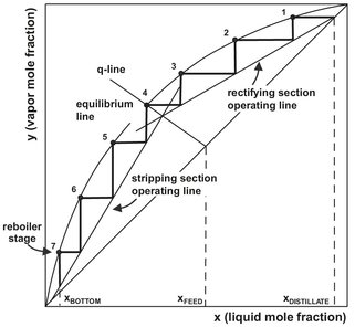
Fig. 6.11: Determination of number of equilibrium stages with the McCabe—Thiele graphical method.
A solution to the material balance and equilibrium relationships inside the column is provided by the graphical McCabe—Thiele design method. It employs the simplifying assumption that the molal overflows in the stripping and rectification sections are constant. As illustrated in Fig. 6.11, this assumption leads to straight operating lines in the rectifying and the stripping section:
![]()
(6.16)
![]()
(6.17)
The constant liquid and vapor molal flows in each section are designated by L and V. Assuming constant molal overflow implies that the molal latent heats of the two components are identical, the sensible heat effects are negligible, and the heat of mixing and heat losses equal zero. This simplified situation is closely approximated for many distillations. In Fig. 6.11, the operating lines relate the solute concentration in the vapor passing upward between two stages to the solute concentration in the liquid passing downward between the same two stages. The equilibrium curve relates the solute concentration in the vapor leaving an equilibrium stage to the solute concentration in the liquid leaving the same stage. This makes it possible to determine the required number of stages by constructing a staircase between the operating line and the equilibrium curve, as shown in Fig. 6.11.
For any distillation operation however, there are infinite combinations of reflux ratios and numbers of theoretical stages possible. The larger the reflux ratio, the fewer theoretical stages are required, but the more energy is consumed. For a given combination of feed, distillate, and bottom compositions, there are two constraints that set the boundary conditions within which the reflux ratio and number of theoretical stages must be. The minimum number of theoretical stages and the minimum reflux ratio. Both can be determined by simple analytical methods that are also applicable to multicomponent mixtures when the two key components are used. Key components are those between which the specified separation must be made. The minimum number of theoretical stages occurs when the operating lines coincide with the y = x line, meaning that the system is at total reflux. The minimum number of stages may again be determined graphically, as illustrated by Fig. 6.12, but an approximate value of the minimum number of equilibrium stages at total reflux can also be obtained from the Fenske equation:
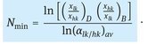
(6.18)
The Fenske equation is also applicable for multicomponent mixtures, because the relative volatility is based on the light key relative to the heavy key. The average value of the relative volatility is generally calculated by taking the average of the relative volatility at the top of column and at the bottom of the column.
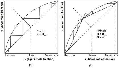
Fig. 6.12: Determination of (a) minimum reflux ratio and (b) minimum number of theoretical stages in a McCabe—Thiele diagram.
Column operation with minimum internal gas and liquid flow (i.e. minimum reflux) separates a mixture with the lowest energy input. On a McCabe—Thiele plot the minimum reflux ratio occurs when the upper and lower operating lines and the feed point (q-line) coincide at a single point on the equilibrium line shown in Fig. 6.12. Under this condition an infinite number of theoretical stages would be required to achieve the desired separation. The Underwood method provides an analytical expression for estimating the minimum reflux ratio:
![]()
(6.19)
If the distillate product is required as a (nearly) pure substance (xD = 1), this equation reduces to
![]()
(6.20)
Both of these limits, the minimum number of stages and the minimum reflux ratio, serve as valuable guidelines within which the practical distillation conditions must lie. The operating, fixed, and total cost of a distillation system depend strongly on the ratio of operating reflux ratio to minimum reflux ratio. As shown by Fig. 6.13, first the fixed costs decrease by increasing the reflux ratio because fewer stages are required, but then rise again as the diameter of the column increases at higher vapor and liquid loads. Similarly, the operating cost for energy increase almost linearly as the operating reflux ratio increases. For most commercial operations the optimal operating reflux ratios are in the range of 1.1 to 1.5 times the minimum reflux ratio.
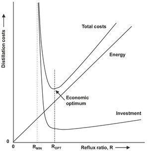
Fig. 6.13: Typical distillation fixed, operating, and total costs as a function of reflux ratio.
6.2.5 Energy requirements
Following the determination of the feed condition, reflux ratio and number of theoretical stages estimates of the heat duties of the condenser and reboiler can be made. When energy losses to the environment are minimal, the feed is at the bubble point and a total condenser is used, the energy balance over the entire column gives
![]()
(6.21)
![]()
(6.22)
The energy balance can be approximated by applying the assumptions of the McCabeThiele method, yielding for the reboiler and condenser duty
![]()
(6.23)
If saturated steam is the heating medium for the reboiler, the required steam rate becomes
![]()
(6.24)
where Δ Hvap is the enthalpy of vaporization of steam (2100 kJ/kg). The cooling water rate for the condenser is
![]()
(6.25)
where CP,water is the specific heat capacity of water (kJ/kg K). In general the cost of cooling water can be neglected during a first evaluation because the cost of reboiler steam is an order of magnitude higher.
6.2.6 Batch distillation
In most large chemical plants distillations are run continuously. For small production units where most chemical processes are carried out in batches it is more convenient to distil each batch separately. In batch distillation, a liquid mixture is charged to a vessel (still) where it is heated to the boiling point. When boiling begins the vapor is passed through a fractionation column and condensed to obtain a distillate product, as indicated in Fig. 6.14. As with continuous distillation the purity of the top product depends on the still composition, the number of plates of the column and on the reflux ratio used. In contrast to continuous distillation, batch distillation is usually operated with a variable amount of reflux. Because the lower-boiling components concentrate in the vapor and the remaining liquid gradually becomes richer in the heavier components, the purity of the top product will steadily drop. This is generally compensated by a gradual increase in reflux ratio during the distillation process to maintain a constant quality of the top product. To obtain the maximum recovery of a valuable component, the charge remaining in the still after the first distillation may be added to the next batch.
The main advantage of batch distillation is that multiple liquid mixtures can be processed in a single unit. Different product requirements are easily taken into account by changing the reflux ratio. Even multicomponent mixtures can be separated into the different components by a single column when the fractions are collected separately. An additional advantage is that batch distillation can also handle sludges and solids. The main disadvantages of batch distillation are that for a given product rate the equipment is larger and the mixture is exposed to high temperatures for a longer time. This increases the risk of thermal degradation or decomposition. Furthermore, it requires more operator attention, energy requirements are higher and its dynamic nature makes it more difficult to control and model.
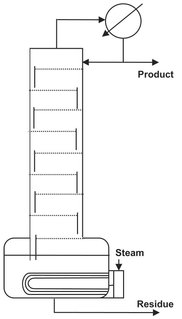
Fig. 6.14: Schematic of a batch distillation unit.
6.2.7 Continuous separation of multiple products
If each component of a multicomponent distillation is to be essentially pure when recovered, the number of required columns is equal to the number of components minus one. Thus, a three-component mixture requires two and a four-component mixture requires three separate columns. Those columns can be arranged in many different ways as illustrated in Fig. 6.15 for the possible separation paths of a ternary mixture.
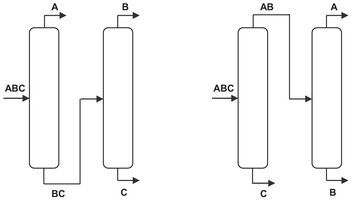
Fig. 6.15: Possible paths for complete separation of a ternary mixture into its pure products.
The more components in the mixture, the more separation paths are possible. Fortunately the separation sequence of multicomponent mixtures is often determined by other limiting conditions such as stability or corrosiveness of individual substances, danger of explosion, toxicity, etc. In all these cases the difficult substance should, if possible, be separated first.
6.2.8 Enhanced distillation techniques
When, due to minimal difference in boiling point and/or highly nonideal liquid behavior the relative volatility becomes lower than 1.1, ordinary distillation may be uneconomic and in case an azeotrope forms even impossible. In that event, enhanced distillation techniques should be explored. For these circumstances the most often used technique is extractive distillation where a large amount of a relatively high-boiling solvent is added to increase the relative volatility of the key components in the feed mixture. In order to maintain a high concentration throughout the column, the solvent is generally introduced above the feed entry and a few trays below the top. It leaves the bottom of the column with the less volatile product and is recovered in a second distillation column as shown in Fig. 6.16. Because the high boiling solvent is easily recovered by distillation when selected in such a way that no new azeotropes are formed, extractive distillation is less complex and more widely used than azeotropic distillation.
In homogeneous azeotropic distillation an entrainer is added to the mixture, forming a homogeneous minimum— or maximum-boiling azeotrope with one or more feed components. The entrainer can be added everywhere in the column. If an entrainer is added to form an azeotrope, the azeotrope will exit the column as the overhead or bottom product leaving behind component(s) which may be recovered in the pure state. A classical example of azeotropic distillation is the recovery of anhydrous ethanol from aqueous solutions. Organic solvents such as benzene or cyclohexane are used to form desirable azeotropes, allowing the separation to be made. As shown in Fig. 6.17, the crude column overhead product is fed to the azeotropic distillation column where cyclohexane is used to form an azeotrope with water. Ethanol is recovered as the bottom product. The overhead azeotropic cyclohexane/water mixture is condensed where water-rich and cyclohexane-rich liquid phases are formed. Residual cyclohexane is removed from the water-rich phase in a stripper.
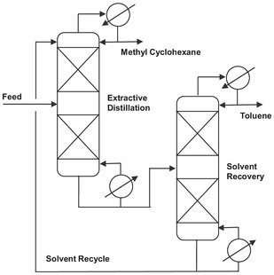
Fig. 6.16: Extractive distillation separation of toluene from methylcyclohexane (MCH) using solvents such as n-methylpyrrolidone (NMP).
It is well known that many minimum-boiling azeotrope-containing mixtures allow the position of the azeotrope to be shifted a change in system pressure. This effect can be exploited to separate a binary azeotrope containing mixture when appreciable changes (> 5 mol %) in azeotropic composition can be achieved over a moderate pressure range. Pressure swing distillation uses a sequence of two columns operated at different pressures for the separation of pressure-sensitive azeotropes. This is illustrated in Fig. 6.18 where the effect of pressure on the temperature and composition of a minimum boiling azeotrope is given. The binary azeotrope can be crossed by first separating the component boiling higher than the azeotrope at low pressure. The composition of the overhead should be as close as possible to that of the azeotrope at this pressure. As the pressure is increased the azeotropic composition moves toward a higher percentage of A and component B can be separated from the azeotrope as the bottom product in the second column. The overhead of the second column is returned to the first column.
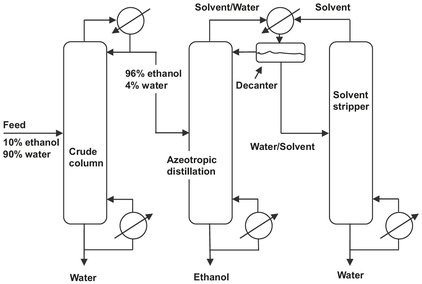
Fig. 6.17: Dehydration of alcohol by azeotropic distillation with cyclohexane as entrainer.
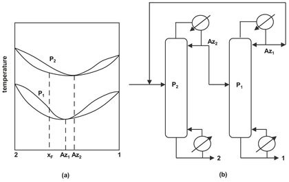
Fig. 6.18: Pressure-swing distillation: (a) I-y-x curves for minimum-boiling azeotrope at pressures P1 and P2; (b) distillation sequence for minimum-boiling azeotrope.