Process Technology: An Introduction - Haan A.B. 2015
6 Evaporative separations
6.3 Distillation equipment
6.3.1 Basic functions
Distillation is usually conducted in vertical cylindrical vessels that provide intimate contact between the rising vapor and the descending liquid. The distillation column normally contains internal devices for effective vapor-liquid contact that provides the opportunity for the two streams to achieve some approach to thermodynamic equilibrium. Their basic function is to provide efficient mass transfer between a two-phase vapor-liquid system. The requirements for efficient mass transfer across the vaporliquid interface can be deduced from
![]()
(6.26)
The maximum mass transfer rate is obtained when all three terms on the right-hand side of the above equation are as large as possible:
· — The mass transfer coefficient kOV increases proportionally with the relative velocities between the liquid and vapor phases and is also improved by constant regeneration of the contact area between the phases.
· — A large contact area A is desirable for mass transfer and mainly determined by the used column internals. Depending upon the type of internal devices used, the contacting may occur in discrete steps, called plates or trays, or in a continuous differential manner on the surface of a packing material. Tray columns and packed columns are most often used for distillation since they guarantee excellent countercurrent flow and permit a large overall height. The internals provide a large mass transfer area, which is constantly renewed, especially in tray columns.
· — The largest concentration driving force (y*—y) is achieved when the overall flow pattern allows countercurrent contact between equal streams of gas and liquid without significant remixing. An important condition is that both phases are distributed uniformly over the entire flow area.
6.3.2 Tray columns
Fig. 6.19 shows the most important features of a tray column. The gas flows upwards within the column through perforations in horizontal trays, and the condensed liquid flows counter currently downwards. However, as indicated in Fig. 6.20, the two phases exhibit cross flow to each other on the individual trays. The liquid enters the cross flow tray from the bottom of the downcomer belonging to the tray above and flows across the perforated active or bubbling area. The ascending gas from the tray below passes through the perforations and aerates the liquid to form a large interfacial area between the two phases. It is in this zone where the main vapor-liquid mass transfer occurs. The vapor subsequently disengages from the aerated mass on the tray and rises to the tray above. The aerated liquid flows over the exit weir into the downcomer where most of the trapped vapor escapes from the liquid and flows back to the interplate vapor space. Some of the liquid accumulates in each downcomer to compensate for the pressure drop caused by the gas as it passes through the tray. The liquid then leaves the tray by flowing through the downcomer outlet onto the tray below. In large diameter crossflow trays, multiple liquid-flow-path trays with multiple downcomers are used to prevent that the hydraulic gradient of the liquid flowing across the tray becomes excessive.
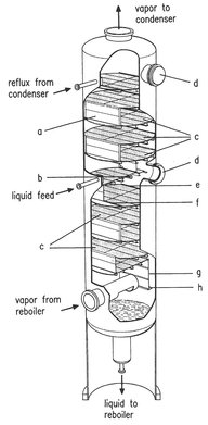
Fig. 6.19: Cutaway section of a tray column (reproduced with permission from [77]).
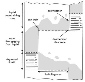
Fig. 6.20: Schematic of flow pattern in a crossflow tray distillation column.
Three principal vapor-liquid contacting devices are used for cross-flow tray design (see Fig. 6.21):
· — Sieve trays have become very important because they are simple, inexpensive, have high separation efficiency, and produce a low pressure drop across the tray. Conventional sieve trays contain typically 1—12 mm holes and exhibit ratios of open area to active area ranging from 1: 20 to 1: 7. If the open area is too small, the pressure drop across the tray is excessive, while if the open area is too large, the liquid weeps or dumps through the holes.
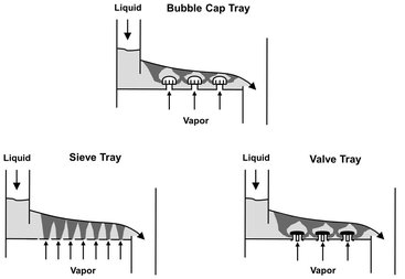
Fig. 6.21: Schematic of a sieve, valve and bubble cap tray.
· — Valve trays are a relatively new development and are a variation of the sieve tray with liftable valve units such as those shown in Fig. 6.22 fitted in the holes. The liftable valves prevent the liquid from leaking at low gas loads and avoids excessive pressure increase at high gas loads. The main advantage is the ability to maintain efficient operation while being able to vary the gas load up to a factor of 4 to 5. This capability gives valve trays a much larger operational flexibility than any other tray design.
· — Bubble cap trays have been used almost exclusively in the chemical industry until the early 1950s. As shown in Fig. 6.21, their design prevents liquids from leaking downward through the tray. The vapor flows through a hole in the tray floor, through the riser, reverses direction in the dome of the cap, flows downward, and exits through the slots in the cap. However, the complex bubble caps are relatively expensive and have a higher pressure drop than other designs. This limits their usage in newer installations to low liquid flow rate applications or to those case where the widest possible operating range is desired.
Although the column requirements are calculated in terms of theoretical or equilibrium stages, the real design must specify the actual number of trays. This requires the determination of the performance of an actual tray to approaching equilibrium. This is often done through the overall tray efficiency, which is defined by the number of theoretical stages divided by the required number of actual trays:
![]()
(6.27)
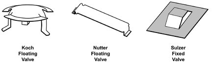
Fig. 6.22: Examples of valves uses in valve trays.
As a result the overall efficiency is an average of all the individual trays. Most hydrocarbon distillation systems in commercial columns achieve overall tray efficiencies of 60—80 %. In absorption processes the range is 10—50 %.
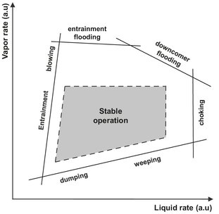
Fig. 6.23: Operating diagram for cross-flow trays.
More detailed column dimensioning requires determination of the entire operating region bound by a range of liquid and vapor flow rates, as shown in Fig. 6.23. The weeping/dumping line represents the minimum operable vapor flow rate at various liquid flow rates. Below the line, the vapor rate is too low to maintain the liquid on the tray, and the liquid weeps or dumps through the tray orifices. At high vapor rates the entrainment line represents the boundary where the gas blows the liquid of the tray in the form of fine droplets. The liquid then no longer flows countercurrently to the gas, and proper column operation ends. The same occurs when the liquid flow through the column becomes larger than the downcomer capacity, and the liquid holdup becomes excessive. Flooding conditions can occur at high liquid rates or by excessive pressure drop across the trays restricting the liquid flow rate through the downcomer. Due to the increased holdup, part of the liquid recycled back to the previous tray with the rising vapor and proper countercurrent column operation breaks down. Although trays can be operated at very low liquid loads, extremely low liquid loads cause an uneven liquid distribution across the tray, which decreases the mass transfer efficiency.
6.3.3 Packed columns
The most important features of a packed column are shown in Fig. 6.24. The vapor enters the bottom of the column and flows upward through the free cross-sectional area of the internals in countercurrent contact with the downflowing liquid. To promote mass transfer the packing should have a large surface area per unit of volume and be wetted by the liquid as completely as possible. Because a countercurrent flow exists throughout the column, packed columns are in principle more effective for mass transfer than tray columns. However, the countercurrent flow of gas and liquid in a packed column is not perfect since the liquid flow is not uniform over the cross section. Well-known mechanisms causing liquid maldistribution are liquid channeling and wall flow. The internals of the column must offer minimum resistance to gas flow. Modern packings have a relative free-cross-sectional area of more than 90 %.
The type of packing used has a great influence on the efficiency of the column. Most industrial packed columns use random packings composed of a large number of specially formed particles. Presently, some 50 different types of random packings are offered on the market. Some examples of the more important types are shown in Fig. 6.25. The oldest packing element is the Raschig ring, with its characteristic feature that the length of the ring is equal to its diameter. This feature makes the particles form quite a homogeneous bed structure during pouring into the column. Raschig rings have a rather high pressure drop, since the walls of those rings in horizontal position block the gas flow. The Pall ring avoids this disadvantage, since parts of the wall are punched out and deflected into the inner part of the ring. A Pall ring has the same porosity and the same volumetric area as a Raschig ring, but a considerably lower pressure drop. The feasible packing size depends on column diameter but should not exceed 1/10 to 1/30 of the column diameter. Most packings are made of metal or ceramics, but plastics are being increasingly used.
A certain degree of inhomogeneity is unavoidable in any random packing. These inhomogeneities, which cause liquid maldistribution, are avoided by using ordered packing structures such as the corrugated sheet structure developed by Sulzer in the mid-1960s. As Fig. 6.26 shows, the corrugated sheets are assembled parallel in vertical direction with alternating inclinations of the corrugations of neighboring sheets. Since the packing does not fit perfectly into the cylindrical column shell, additional tightening strips have to be installed between the packing and column wall. These structured packings provide a homogeneous bed structure, and a low pressure drop due to the vertical orientation of the sheets. It is therefore not surprising that their first applications were found in vacuum distillation. At present, structured packings are available in different types (gauze, sheet) and in a variety of materials (metals, plastics, ceramics, carbon). For most applications, structured sheet metal packings offer a more attractive performance/cost ratio than structured gauze packings, because the cost of structured sheet is about one-third that of gauze, while the efficiencies are about the same. Disadvantages of structured packings are high costs relating to trays, the criticality of the initial liquid and vapor distributions, and the associated hardware required. Typically the installed cost of structured sheet-metal packing plus the associated hardware is about three to four times that for conventional trays.
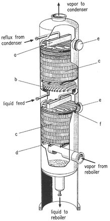
Fig. 6.24: Cutaway section of a packed column with a structured packing. Reproduced with permission from [77].
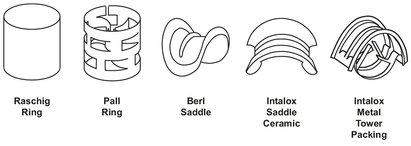
Fig. 6.25: Common random column packings.
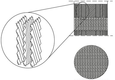
Fig. 6.26: Schematic of corrugated structured packing. Adapted from [77].
Obviously, the most important element of packed column internals is the packing itself. However, some supplementary elements, schematically depicted in Fig. 6.24, are necessary for proper column operation. Good contacting efficiency is only obtained with a uniform liquid distribution over the entire cross-sectional area. For this purpose liquid distributors and redistributors are used. Redistributors are necessary to avoid the buildup of a high degree of liquid maldistribution when the bed exceeds a height of 6 m. Other important supplementary internals are:
· — liquid collectors are installed for the withdrawal of side stream products, pump arounds, and the collection of liquid before each liquid distributor;
· — wall wiper to direct the liquid flowing along the wall back into the packing;
· — support grid is installed to support the packing and the liquid holdup of the packing.
· — the hold down plate has the primary function to prevent expansion of the packed bed as well as to maintain a horizontal bed level.;
· — the gas distributor is used to obtain a uniform gas flow across the column cross section.
A good packing design should have high capacity, high separation efficiency, and large flexibility to gas and liquid throughput. Fig. 6.27 shows a rough comparison of the capacity and separation efficiency of several metal packings. Structured packings are generally superior to random packings in both capacity and separation efficiency. Modern random packings perform better than the standard Raschig and Pall ring packings. In packed columns the height equivalent to a theoretical plate (HETP) or height equivalent to a theoretical stage (HETS) concept is commonly used to represent the mass transfer efficiency and to allow comparison of tray and packed columns. For packed columns the HETP is defined as the ratio of the height of the mass transfer zone containing packing, HP, and the number of equilibrium stages N:
![]()
(6.28)
For tray columns, the mass transfer zone is equal to the tray spacing HTray times the number of trays Nact, giving
![]()
(6.29)
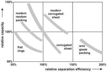
Fig. 6.27: Comparison of the relative capacity and relative separation efficiency of various random and structured packings. Adapted from [77].
The feasible operating region of packed columns differs considerably from tray columns and is limited by flooding and wetting. As illustrated in Fig. 6.28, flooding sets the upper capacity limit. At the flood point the pressure drop of the gas flow through the bed increases so drastically that the liquid is no longer able to flow downward against the gas flow. Hence, the countercurrent flow of gas and liquid breaks down, and the separation efficiency decreases dramatically. In contrast to tray columns, packed columns require a minimum liquid load to ensure sufficient mass transfer. Below this minimum value, only a very small part of the packing surface is wetted, and liquid and gas are no longer in intimate contact. This results in a considerable drop of separation efficiency. The lower capacity limit of a liquid load depends on the type of the packing, the quality of the packing supplements, and the physical properties of the liquid.
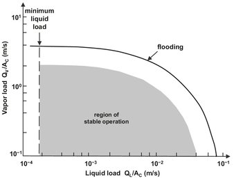
Fig. 6.28: Operating region of a packed column.
6.3.4 Criteria for column selection
Proper choice of equipment is very important for effective and economical distillation. Tray columns are generally employed in large diameter (> 1 m) towers. The gas load must be kept within a relatively narrow range; only valve trays allow greater operational flexibility. The liquid load can be varied over a wide range even down to very low liquid loads. For vacuum operation their relatively high pressure drop (typically 7 mbar per equilibrium stage) is a disadvantage. Tray columns have a relatively high liquid holdup, compensating for fluctuations in feed compositions. However, the resulting high liquid residence time in the column may lead to the decomposition of thermally unstable substances. Tray columns are also relatively insensitive to impurities in the liquid.
Packed columns are used almost exclusively in small diameter (< 1 m) towers. Only structured packings permit the use of packed columns with very large diameters. They are extremely flexible with regard to gas load, but require a minimum liquid load for packing wetting. Structured packings with an extremely small pressure loss, typically under 0.5 mbar per equilibrium stage, are a tremendous advantage in vacuum operation. The danger of decomposition of thermally unstable substances is also less in packed columns because of lower liquid holdup.