Process Technology: An Introduction - Haan A.B. 2015
6 Evaporative separations
6.4 Polymer devolatilization
6.4.1 Introduction
In the production of most polymeric materials the removal of solvents, residual monomers, and other volatile side products is an important operation that can contribute to manufacturing costs as much as the actual polymerization step or monomer costs. These low molecular weight components are often collectively referred to as volatiles, and their presence in the final polymer product is usually undesired. Separating them from the polymer may be performed for several reasons:
· — improvement of polymer properties;
· — monomer/solvent recovery;
· — compliance with health and environmental regulations;
· — elimination of odors;
· — increase the extend of polymerizations (polycondensation).
Since in most cases the contaminants are far more volatile than the polymer, they are removed by evaporation into a continuous gas phase. The process by which volatiles are separated from the bulk polymer is called devolatilization. Although devolatilization can be carried out with the polymer in the solid state, it is more commonly performed in the molten phase with the polymer above its glass transition temperature or above the melting temperature for crystalline polymers. Devolatilization in the solid state behaves more like a drying process and is therefore not discussed in this chapter.
Melt devolatilization is often the intermediate step between polymerization and product finishing in which solvents and residual monomers are recovered. Separation is effected by pressure reduction, applying vacuum, or by adding inert substances such as nitrogen gas or steam. Difficulties arise from the very viscous nature of the materials being handled and the severe heat and mass transfer limitations. Examples are the bulk polymerization process for polystyrene and solution polymerization processes for polyethylene and EPDM. To enhance end-product properties, devolatilization is also carried out in secondary processes such as compounding of plastics, or processes involving polymer modification. In these operations extrusion-type machinery fitted with venting capability are most commonly used.
6.4.2 Basic mechanisms
Devolatilization of molten polymers is a thermodynamically driven, mass-transfer limited separation process. One of the basic parameters of interest is the maximum degree of separation that may be obtained. This is determined by the thermodynamic equilibrium relating the composition of the polymer to the partial pressure of the volatile solvent in the gas phase:
![]()
(6.30)
where the solvent volume fraction Φs is used for composition, ![]() is the saturated vapor pressure of the pure volatile solvent, and γs is the solvent activity coefficient that comes from the Flory—Huggins theory:
is the saturated vapor pressure of the pure volatile solvent, and γs is the solvent activity coefficient that comes from the Flory—Huggins theory:
![]()
(6.31)
In eq. (6.31), χ represents the Flory—Huggins binary interaction parameter. An example of the resulting pressure-composition diagram is shown in Fig. 6.29. For sufficiently small contaminant concentrations these equations take the form of Henry’s law:
![]()
(6.32)
where
![]()
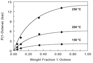
Fig. 6.29: Pressure-composition diagram for the LLDPE/1-octene system.
In actual devolatilization processes with finite residence times, equilibrium is never attained. The overall mechanism is generally described by a combination of volatile transport to a polymer-vapor interface, evaporation of volatiles at the interface, and their subsequent removal by a vacuum system. For most polymer-volatile systems, the time it takes to achieve a certain degree of separation is strongly dependent on the volatile migration rate through the polymer. This migration rate is relatively high in flash evaporation, where the molten feed stream contains large amounts of solvent. Application of a reduction in pressure such that the pressure is less than the vapor pressure of the solvent to the superheated polymer solution initiates boiling or foaming. As shown schematically in Fig. 6.30, these bubbles may then grow, coalesce, and finally rupture at the polymer-vapor interface, where they release their volatile contents to the vapor phase. The bubble growth is determined by the diffusion rate of the volatile material from the polymer bulk to the bubble surface and the resistance of the viscous polymer melt to displacement by the growing bubble. During flash evaporation the evaporation rate is frequently controlled by the rate of heat transfer through equipment walls to the polymer. This is because of the large amount of latent heat required and the notoriously poor polymer heat-transfer coefficient.
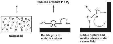
Fig. 6.30: Sequential process steps during bubble-assisted devolatilization. Adapted from [69].
At low volatile concentrations large amounts of latent heat are no longer required, and the devolatilization rate becomes completely diffusion controlled. This is true for the migration of volatiles directly to the surface as well as to bubble nucleation sites and vapor bubbles that grow within the polymer melt. The diffusion in concentrated polymer solutions is several orders of magnitude smaller than in low-molecular-weight liquids. It can be strongly enhanced by increasing the temperature of the system. An additional reason for devolatizing at high temperatures is the increase in the vapor pressure of the volatile component.
6.4.3 Multistage operation and devolatilization aids
In the design of a separation system, one often has the knowledge of feed composition and the required residual volatile level in the exiting stream. Two extreme situations that require special consideration are large separation loads and/or stringent requirements for residues in the end product. When the total separation requirements exceed one order of magnitude, it is often beneficial to use several separation stages that operate at different absolute pressures, to achieve the desired separation. At the higher pressures the bulk of the volatiles are removed, thereby strongly reducing the demand on the high-vacuum system. Finally the residual traces of the volatile component can then be removed at high vacuum with minimal load. The devolatilization efficiency in those final stages is commonly increased by the intentional addition of small amounts of a devolatilizing aid (stripping agent) to the polymer. Introduction of an inert substance enhances devolatilization in several ways:
· — it reduces the partial pressure of the volatile component and therefore increases the concentration gradient for devolatilization;
· — the additivity of vapor pressures induces boiling/foaming in the polymer solution at a lower temperature and volatile concentration;
· — boiling of the inert substance creates bubbles that increase the area available for mass transfer from the polymer to the vapor phase.
Both staging and stripping agent addition are often combined in devolatizing extruders, as shown in Fig. 6.31. In the backward and first forward devolatilization zones the polymer melt is degassed only by increased vacuum. The final two devolatilization zones use the addition of a stripping agent for enhanced efficiency. The stripping agent (water, nitrogen, carbon dioxide) should be of low cost, inert, easily recoverable, and tolerable in trace quantities in the final product. Additional advantages of staging are the reduction of polymer entrainment arising from the high vapor velocities in the initial stages and the opportunity to reheat the polymer between the stages to compensate the evaporative cooling.
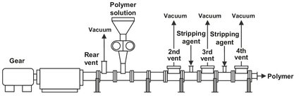
Fig. 6.31: Multistage devolatizing extruder installation.
6.4.4 Devolatilization equipment
A variety of commercial equipment is available for the industrial separation of volatile components from the base polymer matrix. The equipment may be broadly classified as nonrotating and rotating equipment. Some of the main units in each category are:
· — nonrotating devolatizers:
o — Flash evaporators;
o — Falling-film devolatizers;
o — Falling-strand devolatizers;
· — rotating devolatizers:
o — thin-film evaporators;
o — single-screw extruders;
o — double-screw extruders;
o — kneaders.
In nonrotating equipment, gravitational forces transport the polymer through the devolatilization zone. Thermal energy is usually introduced by heating the polymer melt under pressure in an external heat exchanger. In rotating equipment the melt is conveyed by its contact with moving elements, and devolatilization is significantly enhanced because of mechanical agitation. Thermal energy is introduced into molten polymers by direct heat transfer of heat through equipment walls and transformation of mechanical energy (shaft work) into thermal energy via viscous dissipation. The mechanical introduction of heat is significant only when the polymer melt viscosity is sufficiently high. Accordingly, the viscosities that nonrotating devolatizers may handle are much lower than those processed in rotating equipment.
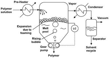
Fig. 6.32: Schematic of a flash evaporation devolatizer.
For polymer solutions with a high volatiles concentration and relative low viscosity, simple flash evaporation is the preferred process. In flash evaporators, schematically shown in Fig. 6.32, the liquid to be devolatilized is first heated in an external heat exchanger. The superheated solution under pressure is then flashed into an expansion tank where the pressure is relieved with an overhead vent for vapor removal. Because the sudden pressure reduction promotes foaming and the low solution viscosities, heat and mass transfer limitations are small and extensive, surface renewal is not necessary. The heat of evaporation is obtained at the expense of the sensible heat of the feed solution. The devolatilized polymer melt is usually not very viscous and can be discharged from the evaporating chamber using a gear or screw pump. A specific configuration of a flash chamber is the falling strand devolatizer, shown in Fig. 6.33, where the material is extruded into a multitude of strands and allowed to fall by gravity, while flashing, into a melt pool. The free fall of strands allows easy disengagement of the already grown bubbles.
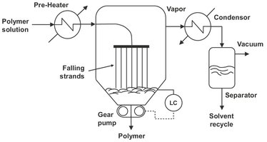
Fig. 6.33: Schematic of a falling strand devolatizer.
The equipment used to handle more viscous polymer solutions usually contains rotating parts that not only aid forward movement of the material but also impart surface renewal for heat and mass transfer. Thin-film evaporators are a modification of the falling-film evaporator. In the latter, a thin liquid film flows by gravity down the inner wall of a vertical cylinder and contacts a vapor stream that passes through the center of the cylinder. For polymer devolatilization, the equipment is modified to accommodate the higher viscosities of the liquid phase. Fig. 6.34 shows a cross section of a vertical thin film evaporator. The apparatus comprises of a vertical heated drum within which a mechanical agitator rotates. The incoming liquid is first distributed evenly along the inside of the heated body and flows downward by gravity. The revolving rotor comprises several blades that spread the down-flowing solution into thin films. Thus, a film is deposited on the wall, which provides a large surface area for the evaporation of the contaminant. Evaporated vapors leave the solution through the core of the evaporator, either in a cocurrent fashion (high volatile content) or countercurrent fashion (residual volatiles removal). For high viscosity fluids, the downward flow is aided by pitched instead of straight rotor blades which provide a downward motion to assist polymer flow.
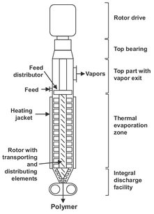
Fig. 6.34: Schematic of a thin film evaporator.
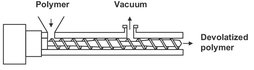
Fig. 6.35: Schematic of a devolatilization extruder.
For highly viscous, difficult to pump polymers, vented, single-, or multiscrew extruders are the commonly used devolatizers (Fig. 6.35). Extruders can efficiently handle fluids with viscosities varying over several orders of magnitude on the same shaft. They can be used stand-alone or in combination with other polymer-processing functions. In the extruder the rotating screw conveys the polymer melt from the hopper to the exit by a combination of drag and pressure flow. Heat is introduced by heating through the barrel wall and generated by viscous dissipation. The vent zone of a screw extruder has deep channels to provide a pressure-free zone in which the polymer is exposed to lower pressures or vacuum. Devolatilization is considered to occur through two supporting parallel evaporation processes. This is illustrated in Fig. 6.36, which shows a schematic of this process. Firstly the vented section of the screw channel is partially filled with rotating polymer melt. Secondly the clearance between the barrel and the screw flight deposits a thin layer of polymer on the barrel as the screw flight rotates. As a result evaporation occurs either at the surface of the rotating bulk or at the surface of the deposited films. Both mechanisms are subject to surface renewal. The polymer melt pool through cross-channel, drag-induced flow, and the film via periodic introduction into the mixed pool. It is therefore no surprise that the separation efficiency is strongly dependent upon the screw speed.
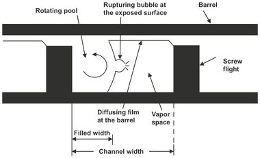
Fig. 6.36: Schematic of surface evaporation in a partially filled vented extruder channel. Adapted from [69].
Nomenclature
A |
interfacial area |
[m2] |
B |
bottom product flow |
[mol s-1] |
CP |
specific heat capacity |
[J kg-1 K-1] |
D |
top product flow |
[mol s-1] |
E0 |
overall plate efficiency |
[—] |
F |
feed flow |
[mol s-1] |
H |
height |
[m] |
HETP |
height equivalent of a theoretical plate |
[—] |
HETS |
height equivalent of a theoretical stage |
[—] |
ΔHvap |
molar heat of vaporization |
[J mol-1] |
Ki |
distribution coefficient of component i |
[—] |
k |
mass transfer coefficient |
[m s-1] |
L |
liquid flow (in rectifying section L′, in stripping section L″) |
[mol s-1] |
m |
mass rate |
[kg s-1] |
N |
number of (theoretical) stages |
[—] |
p |
partial pressure |
[N m-2] |
P0 |
saturation pressure |
[N m-2] |
Ptot |
total pressure |
[N m-2] |
Q |
heat flow |
[J s-1] |
R |
reflux ratio L′/D |
[—] |
T |
temperature |
[K] |
V |
vapor flow (in rectifying section V′, in stripping section V″) |
[mol s-1] |
w |
weight fraction |
[—] |
x, y, z |
mole fraction (liquid, vapor, feed) |
[-] |
αij |
selectivity, relative volatility or equilibrium constant |
[—] |
X |
Flory-Huggins binary interaction parameter |
[—] |
φ |
volume fraction |
[—] |
Φ |
mass transfer rate |
[kg s-1] |
γ |
activity coefficient |
[—] |
p |
density |
[kg m-1] |
Indices
1, 2, i, j |
components |
act |
actual |
av |
average |
B |
bottom |
C |
condenser |
D |
distillate |
F |
feed |
L |
liquid |
lk |
light key |
hk |
heavy key |
MIN |
minimum |
OV |
overall based on vapor phase |
P |
packing |
P |
polymer |
R |
reboiler |
S |
solvent |
V |
vapor |