Process Technology: An Introduction - Haan A.B. 2015
10 Solid-liquid separation
10.2 Gravity sedimentation
Gravity sedimentation is a process of solid-liquid separation under the effect of gravity. A slurry feed is separated into an underflow slurry of higher solids concentration and an overflow of substantially clear liquid. A difference in density between the solids and the suspending liquid is a necessary prerequisite. Flocculation agents are often used to enhance settling.
Sedimentation is used in industry for solid-liquid separation and solid-solid separation. In solid-liquid separation, the solids are removed from the liquid either because the solids or the liquid are valuable or because these have to be separated before disposal. If the clarity of the overflow is of primary importance, the process is called clarification and the feed slurry is usually dilute. If the primary purpose is the production of concentrated slurry, the process is called thickening and the feed slurry is usually more concentrated. In solid-solid separation, the solids are separated into fractions according to size, density, shape, or other particle properties. Sedimentation is also used for size separation of solids. One of the simplest ways to remove the coarse or dense solids from a feed suspension is by sedimentation. Successive decantation produces closely controlled size fractions of the product. In all cases the assessment of the sedimentation behavior of the solids within the fluids will allow the correct size of vessel to be determined. It is therefore important to know about the way in which settling solids behave during sedimentation.
10.2.1 Sedimentation mechanisms
Gravity sedimentation is the separation of particles from fluids under the effect of gravity. The particle sedimentation rates are dependent upon particle properties such as size, size distribution, shape, and density. Materials with particle diameters of the order of a few microns settle to slow for most practical operations. Wherever possible, such particles are agglomerated or flocculated into relatively large clumps called flocs, which settle out more rapidly. Spherical or near-spherical particles and agglomerates settle faster than plate or needle-like particles of similar weights. Other readily recognized factors to be considered are the density and viscosity of the surrounding medium.
The main factors that determine the behavior of a settling suspension are the concentration of the particulate solids and the state of aggregation of the particles. Their effect on the characteristics of sedimentation are best understood through analyzing a batch settling experiment, as in Fig. 10.5. Solid particles without the tendency to cohere with each other generally settle at a steady rate and are described as discrete particles. At low solids concentrations, the individual particles are generally able to settle as individuals, while the fluid which is displaced flows upward between them. Regardless of their properties, the particles are sufficiently far apart to settle freely in this dilute sedimentation region. Contact between two flocculent particles may result in cohesion, resulting in an increase in size and hence a more rapidly sedimenting particle.
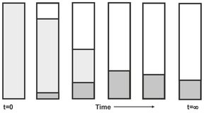
Fig. 10.5: Schematic of a batch sedimentation experiment.
Increasing the particle concentration in a fluid decreases the settling rate of each individual particle. This phenomenon, known as hindered settling, is readily appreciated if it is considered that the settling of each particle is accompanied by a return flow of the sedimentation liquid. Since the fluid is unable to pass through the particles, its velocity must increase to compensate for this partial blocking of the flow channel. The relative velocity effect, however, does not completely account for the slowing of sedimentation with increases in solids concentration. Particle interference by collision and coagulation are some other factors. For flocculent particles the effect of initial solids concentration on sedimentation behavior has been observed to exhibit three quite distinct modes. In dilute suspensions, the individual particles or flocs again behave as discrete particles. At intermediate concentrations the flocs, which are in loose mutual contact, settle by channeling. The channels are of the same order of magnitude as the particles and are developed during an induction period in which an increasing quantity of return fluid forces its way through the mass.
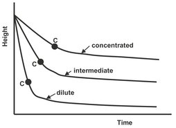
Fig. 10.6: Effect of concentration on sedimentation.
Particles near the bottom of the cylinder pile up into a concentrated sludge, whose height increases as more particles settle. This continues until the suspension zone disappears and all the solids are contained in the sediment. This condition, illustrated in Fig. 10.6, is known as the critical sedimentation point. Until this point is reached, the solid-liquid interface follows an approximately linear relationship with time. In such concentrated suspensions however, fluid flow is only possible through the minute voids between the primary particles. The resistance of the touching particles below drastically reduces the sedimentation rate to a relatively low compaction rate. In this compression regime the rate of sedimentation is a function of both the solids concentration and the depth of settled material in the tank. Particles closer to the base will be compressed by the mass of solids above, resulting in more concentrated sediment by slowly expelling the liquid, which accompanies the flocs into the deposit. This continues until equilibrium is established between the weight of the flocs and their mechanical strength. These effects of particle coherence and concentration of the settling characteristics of a feed suspension is summarized in Fig. 10.7. It is important to realize that although the feed stream may start in one regime, it may pass through all of these regimes during clarification or thickening.
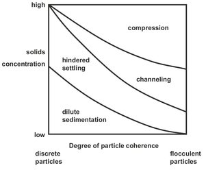
Fig. 10.7: Effect of particle coherence and solids concentration on the settling characteristics of a suspension.
10.2.2 Rate of sedimentation
Newton’s second law of motion describes the movement of a small solid particle through a viscous liquid under the influence of gravity. For a free-falling sphere with mass mp, the nonstationary momentum balance reads
![]()
(10.1)
An important parameter that characterizes the nature of liquid flow around the particles is the particle Reynolds number Rep. For spherical particles that sediment under laminar flow conditions Stokes’ law can be used to describe the drag force and the force balance equation becomes
![]()
(10.2)
After a short initial acceleration period, the particle will attain a constant velocity, which is calculated by taking its apparent weight equal to the resistance force and setting the acceleration term to zero. This gives the so-called terminal settling velocity vt of a single sphere in a viscous liquid:
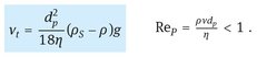
(10.3)
The above expression shows that the sedimentation of a particle is determined by the physical characteristics of the particle and the continuous phase. Increased sedimentation rates are obtained for larger particle diameters, greater density difference between the particle and the continuous phase, and lower viscosity of the continuous phase. However, as the concentration of the suspension increases, the particles get closer together and no longer settle as individuals. Because the fluid must move in the opposite direction, it needs to flow through a smaller space as the particle concentration is increased and the rate of sedimentation in a swarm of particles is reduced compared to that of a single particle. This hindered rate of sedimentation appears to depend only on the fraction of the volume taken up by the particles:
![]()
(10.4)
where Vs is the hindered settling velocity of a particle with terminal settling velocity vt. The void fraction is the volume fraction of the fluid defined by
![]()
(10.5)
The voidage function f(ε) has different forms, depending on the theoretical approach adopted. A well-usable empirical relation is that of Richardson and Zaki:
![]()
(10.6)
These correlations apply only to the cases where flocculation is absent. Suspensions of fine particles often flocculate and therefore show different behavior.
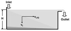
Fig. 10.8: Tank for continuous removal of solids particles from a process liquid.
10.2.3 Design of continuous sedimentation tanks
Fig. 10.8 illustrates a tank for the continuous removal of solids particles from a process liquid. The liquid is introduced at one end of the tank and flows towards the outlet at the other end. The dispersed particles are separated out and fall to the bottom with their terminal settling velocity vt. These processes are described most simply by the ideal continuous sedimentationtank model, which equates the required settling time of the particle and the residence time derived from the horizontal flow of the liquid. The residence time t of the liquid in the tank is obtained by dividing the volume V of the tank by the volumetric flow rate of liquid Q:
![]()
(10.7)
where H is the tank depth and A its area. During the same time t, the particle must have time to fall to the bottom of the tank; thus,
![]()
(10.8)
Since the time is equal in both cases, the two expressions may be equated and the depth of the tank is eliminated from the equations:
![]()
(10.9)
Two important conclusions may be drawn from eq. (10.9). The first is that the height H of the tank does not influence the throughput. The second is that the throughput of this type of tank is directly proportional to the area that can be utilized for separation. Accordingly an increased throughput Q is obtained when the tank area A is increased through fitting in a number of horizontal plates, as illustrated in Fig. 10.9. This increases the number of separation channels to N, giving for the total throughput of the tank
![]()
(10.10)
It is therefore the total area N. A that determines the throughput. In the case of continuous separation, horizontal channels will eventually become clogged with sediment, and separation will cease. If inclined plates are used as shown in Fig. 10.10, the sediment slides down the plates under the influence of gravity and collects at the bottom of the tank.
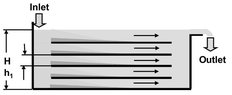
Fig. 10.9: Tank with horizontal plates.
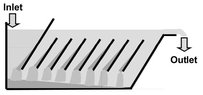
Fig. 10.10: Tankwith inclined plates.
10.2.4 Gravity sedimentation equipment
Two distinct forms of sedimentation vessels are in common usage. The clarifier is used for the clarification of a dilute suspension to obtain an overflow containing minimal suspended solids. In a thickener the suspension is concentrated to obtain an underflow with a high solids content while also producing a clarified overflow. Sedimentation equipment can be divided into batch settling tanks and continuous thickeners of clarifiers. Most commercial equipment is built for continuous sedimentation in relatively simple settling tanks.
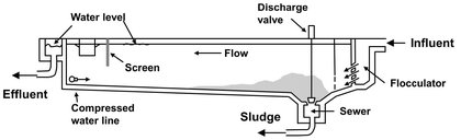
Fig. 10.11: A schematic diagram of a one-pass clarifier with a flocculator.
The largest user of clarifiers is probably the water treatment industry. The conventional one-pass clarifier shown in Fig. 10.11 uses horizontal flow in circular or rectangular vessels with the feed at one end and overflow at the other. The feed is pre-flocculated in a paddle flocculator. Settled solids are pushed to a discharge trench by paddles or blades on a chain mechanism or suspended from a traveling bridge. Circular basin clarifiers are most commonly fed through a centrally located feed well. The overflow is led into a trough around the periphery of the basin. The bottom gently slopes to the center, and the settled solids are pushed down by a number of scraper blades. The conventional one-pass clarifier is designed for the lowest specific overflow rate, which is typically 1-3 m/hr, depending on the degree of flocculation.
The most common thickener is the circular basin type shown in Fig. 10.12. After treatment with flocculant, the feed stream enters the central feed well, which dissipates the stream’s kinetic energy and disperses it gently into the thickener. In an operating thickener the downward increasing solids concentration gives stability to the process. The settling solids and some liquid move downward. Most of the liquid flows upward and into the overflow, which is collected in a trough around the periphery of the basin. Thickeners are widely used, particularly in the mineral processing industry and in wastewater treatment. Stacking of sedimentation units in vertical arrangements increases the capacity per unit area. A development in this category is the lamella thickener (Fig. 10.13), which consists of a number of inclined plates stacked closely together. The feed enters the stack from the side feed box. The flow moves upward between the plates while the solids settle onto the plate surfaces and slide down into the sludge hopper underneath.
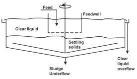
Fig. 10.12: The circular basin continuous thickener.
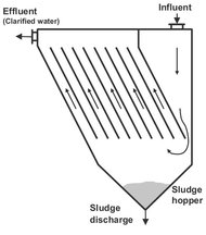
Fig.10.13: A lamella thickener.