Process Technology: An Introduction - Haan A.B. 2015
10 Solid-liquid separation
10.3 Centrifugal sedimentation
Centrifugal sedimentation increases the force on particles over that provided by gravity and extends sedimentation to finer particle sizes and to emulsions that are normally stable in the gravity field. Centrifugation equipment is divided into rotating-wall (sedimenting centrifuges) and fixed-wall (hydrocyclones) devices.
10.3.1 Particle velocity in a centrifugal field
In a liquid-filled rotating vessel, the generated centrifugal acceleration increases with the distance of the particle from the axis of rotation and the angular velocity. The centrifugal acceleration is described by
![]()
(10.11)
which acts towards the center of a circle for a restrained object. Particles in suspension are unrestrained and free to move tangentially outward from the center of rotation with a centrifugal acceleration equal and opposite to the centripetal force. Replacing the gravitational acceleration in eq. (10.3) by the acceleration in a centrifugal field provides the sedimentation velocity of particles in a rotating vessel. However, unlike in gravity settling where the acceleration is constant, the particle velocity in a centrifugal field depends on the radial distance from the center because the radius r appears in the acceleration expression. Hence, to derive the design equations for centrifugal sedimenting machines, the velocity must be written in the differential form
![]()
(10.12)
Comparison of eq. (10.12) with (10.3) provides the commonly quoted g-factor:
![]()
(10.13)
10.3.2 Sedimenting centrifuges
Industrial centrifuges are commonly divided into batch, continuous, and semicontinuous. The common laboratory centrifuge is a simple batch bottle centrifuge designed to handle small batches of material for laboratory separations. The basic structure is usually a motor-driven vertical spindle supporting various heads or rotors. There are three types of rotors: swinging bucket, fixed-angle head, and small perforate or imperforate baskets for larger quantities of material. The bottle centrifuge is often used for preliminary testing to provide the basis for the design of commercial centrifuges.
Process centrifuges are more complex and available in a variety of sizes and types. Tubular centrifuges are used to separate liquid-liquid mixtures or to clarify liquid-solid mixtures with less than 1 % solids content and fine particles. The solids are collected at the bowl wall and removed manually when sufficient bowl cake has accumulated. Liquid is discharged continuously. As the name suggests, these machines (Fig. 10.14) have long tubular bowls that rotate around their vertical axis. Feed material is introduced at the base of the rotor. The longer the feed material spends in the bowl, the longer the centrifugal force is allowed to act on the particles, resulting in a progressively clarified feed stream as it flows up the length of the tubular bowl. Multichamber centrifuges, Fig. 10.15, utilize a closed bowl that is subdivided into a number of concentric vertical cylindrical compartments through which the suspension flows in series. Their efficiency is high because of the reduced travelling distance to the collecting surface. Cleaning of multichamber centrifuges is more difficult and takes longer than for the tubular type.
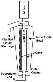
Fig. 10.14: A tubular centrifuge.
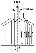
Fig. 10.15: Schematic of a multichamber bowl.
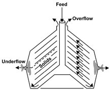
Fig. 10.16: Clarifying disk stack centrifuge.
Centrifuges that channel feed through a large number of conical disks combine high flow rates with high theoretical capacity factors. The basic idea of increasing the settling capacity by using a number of layers in parallel is the same as the lamella principle in gravity sedimentation. Both liquid-liquid and liquid-solid separations are performed for slurries with solids concentrations below 15 % and small particle sizes. The general flow patterns in a disk stack centrifuge are illustrated in Fig. 10.16. Feed enters near the center of the bowl from either the top or the bottom. The clarified medium is discharged at a relatively small radius, generally at the top of the bowl. Solids are collected at the underside of the disks, slide outward along the surfaces, and finally move from the outer edges of the disks to the bowl wall by free settling. Continuous solids discharge is achieved by sloping the inner walls of the bowl towards the discharge point. Generally disk centrifuges have the best ability to collect fine particles at a high rate.
Scroll centrifuges or decanters discharge solids continuously and usually drier than disk and imperforate bowl centrifuges. The feed is introduced through a stationary axial tube. Solids are collected on the bowl wall by sedimentation and continuously moved up a sloping beach by a helical screw conveyor operating at a differential speed with respect to the bowl. As shown in Fig. 10.17, the solids discharge is usually at a radius smaller than that of the liquid. Centrifugal fields are lower than in disk or tubular centrifuges because of the conveyor and its associated mechanism. For clarification, this type of centrifuge recovers medium and coarse particles from feeds at high or low concentrations of solids.
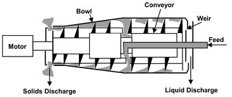
Fig. 10.17: Continuous-scroll discharge decanter.
10.3.3 Bowl centrifuge separation capability
The separation capability of cylindrical bowl centrifuges can be analyzed by equating the time required for settling of a spherical particle to the bowl wall to the time required for the feed liquid to travel to the discharge. In the model derivation plug flow is assumed to apply for the liquid flowing down the machine axis. The particles are considered to settle under Stokes conditions and reach their terminal settling velocity the moment they enter the centrifuge pond. The particles that reach the wall of the centrifuge are removed from the system, while particles that do not reach the wall will be swept out of the machine in the overflow. Under these conditions the particle just captured within the centrifuge will travel along the critical particle trajectory shown in Fig. 10.18. The critical particle trajectory reflects the particle diameter for which the trajectory goes from the top surface (inner radius) of the centrifuge bowl to the bottom surface (outer radius) in the residence time within the machine. Particles of a similar diameter entering the machine between r1 and r2 will not present a problem, as they will follow a parallel trajectory and intercept the wall before the end of the machine.
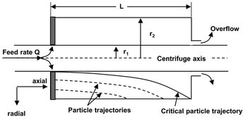
Fig. 10.18: Critical particle trajectory for 100 % capture efficiency.
The residence time of the particle in the axial direction equals
![]()
(10.14)
where Vc is the volume of the centrifuge and Q is the volume flow rate of material fed to the machine. The radial velocity of the sedimenting particles is given by eq. (10.12). Integrating this equation using the limits of r = r1 at t = 0, and r = r2 at t = t, and rearranging for the sedimentation time gives
![]()
(10.15)
Equating the equation for the sedimentation time to that for the residence time yields the bowl centrifuge separation capability:
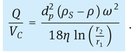
(10.16)
10.3.4 Hydrocyclones
Hydrocyclones offer one of the least expensive means of solid-liquid separation from both an operating and an investment viewpoint. They are cheap, compact, versatile, and similar in operation to a centrifuge, but with much larger values of g-force. This force is, however, applied over a much shorter residence time. The most significant difference with a centrifuge is that centrifugal forces are generated without the need for any mechanically moving part other than a pump. The energy needed for the rotation of the liquid is delivered by the velocity of that liquid. Cyclones have been employed to remove solids and liquids from gases and solids from liquids and are operated at temperatures as high as 1000 °C and pressures up to 500 bar.
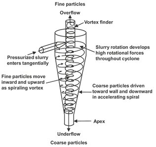
Fig. 10.19: Principal features and flows inside a hydrocyclone.
The principle features and flow patterns are shown schematically in Fig. 10.19. In a hydrocyclone the liquid path involves a double vortex, with the liquid spiraling downward at the outside and upward at the inside. The primary vortex at the outside carries suspended material down the axis of the hydrocyclone. In the inside, material is carried up the axis and into the overflow vortex finder by the secondary vortex. The overflow usually consists of a dilute suspension of fine solids, while the underflow is a concentrated suspension of more coarse solids. Depending on their design, either the thickening or classifying action of the hydrocyclone is enhanced. The long cone shown in Fig. 10.20 provides thicker underflow concentrations, but poorer sharpness of separation than the long cylinder. The vortex finder is important in reducing the loss of unclassified material.
As a first approximation a hydrocyclone can be considered to be a rolled-up settling chamber in which gravitational acceleration is replaced by centrifugal acceleration. A good separation is obtained when the settler criterion is fulfilled:
![]()
(10.17)
Although Fig. 10.21 illustrates that this criterion gives a reasonable indication where the separation can be expected, the distinction between particles that are and are not separated by hydrocyclones is in reality not so sharp. The poor sharpness of separation can be overcome by employing hydrocyclones in series, as illustrated in Fig. 10.22.
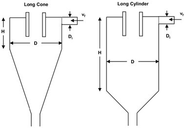
Fig. 10.20: Basic hydrocyclone designs.
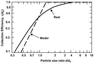
Fig. 10.21: Comparison between theory and practice for the separation efficiency of a hydrocyclone.
High retention efficiency of solids is obtained in hydrocyclones of low diameter. This imposes limitations on the throughput of a single device. Therefore it is common to install packages with multiple hydrocyclone units operating in parallel.
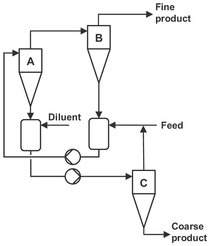
Fig. 10.22: Multicyclone arrangement for sharper separation.