Process Technology: An Introduction - Haan A.B. 2015
14 Solids finishing technologies
14.3 Size reduction
Size reduction or comminution of solids is an important industrial unit operation that is used to reduce the size of individual pieces. The goal of size reduction depends on the final application but is typically covered by preparing raw materials for subsequent processing. Some examples are:
· — ore preparation to allow concentration of the valuable fraction;
· — preparation of raw material for subsequent reactions;
· — production of a defined particle size distribution necessary for a final application (fillers for plastics, rubber and paint, food, pharma);
· — preparation of waste materials for recycling (shredding of old tires and waste plastic granulation).
The size of operation ranges from a few kilograms per hour for specialty products to hundreds of tons for metallurgical extractive purposes. In many operations lumps of up to a meter in size must be reduced to a fine powder of less than 100 µm. It is clear that this size reduction cannot be efficiently achieved in a single machine. A sequence of different types are used, each designed for efficient operation on a particular feed size. The science of size reduction still relies heavily on experience. It is important that requirements be discussed intensively with equipment manufacturers and large-scale test work be carried out before decisions are made on the most suitable methods for a given requirement.
In industrial practice, mills are frequently operated in closed circuit. Fig. 14.16 illustrates that the ground product is passed through a size classifier that separates the mill product in the final product and a coarser stream that is returned to the mill feed. The general reason for closed circuit operation is to remove particles that are already fine enough, to prevent energy being wasted on grinding them even finer. The return of fine material back to the mill feed decreases efficiency as a result of overgrinding. The function of efficient classification is to reduce the proportion of fine material by avoiding overgrinding in-size material or fines. The concept of indirect inefficiency is that although a mill may be operating efficiently in transferring input energy to breakage it can be inefficient if that energy is used to break material that already meets specifications.
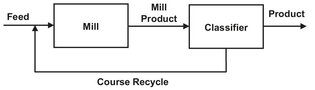
Fig. 14.16: Normal closed mill circuit.
Size-reduction equipment cannot be operated without auxiliary devices, such as bunkers, feeders, feed-control and conveying equipment. This auxiliary equipment is often responsible for weaknesses and disturbances in size-reduction as well as drying plants.
14.3.1 Particle breakage
In size reduction processes, lumps of solids must be fractured by subjecting the material to contact forces or stresses. The stresses are applied by transmitting mechanical force to the solid. In addition, most grinding machines have some degree of impact stress that propagates stress waves through the solid, activating flaws to fracture in the process. These forces cause deformation, which generates internal stress in the particles, followed by particle breakage when this stress reaches a certain level. It is important to differentiate between elastic and plastic deformations within materials. With brittle materials, the behavior is mainly elastic until the fracture point is reached, at which point breakage occurs. An elastic material can be stressed, producing deformation, and the material returns to its original shape when the stress is removed. However, if the solid is stretched too far, catastrophic failure occurs, and the solid fractures at a stress which is termed the tensile strength. Plastic or inelastic deformations are encountered in ductile materials that undergo a partially irreversible stretching before failure occurs. Fig. 14.17 compares the stress-strain characteristics of brittle and ductile materials.
The total area under the stress-strain curves is the strain energy stored in a body. This energy is not uniformly distributed throughout the material but concentrated around the tips of existing cracks or flaws. This local stress concentration initiates crack propagation and gives rise to particle failure. A crack propagates when the overall stress around the crack reaches a critical value. As crack propagation progresses, the strain energy released exceeds the energy associated with new surface formation. The excess energy concentrates around other cracks in the material, causing multiple fractures. This is typical behavior in elastic materials such as rocks, ores, and coals that undergo brittle fracture through pre-existing Griffith flaws. The strength or grind ability of these materials correlates only weakly with the chemical bond strength, because the number, size, and orientations of the flaws basically determine particle strength.
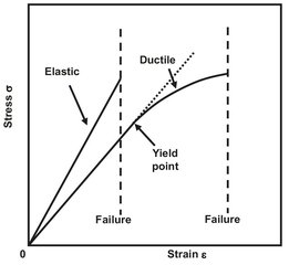
Fig. 14.17: Illustration off stress-strain curves for elastic and ductile materials.
A comparison between the failure of brittle and ductile materials shows the following major features:
· (1) Purely brittle failure is almost independent of temperature. Ductile materials exhibit a decrease of strength with increasing temperature, owing to a greater mobility of dislocations.
· (2) For failure from Griffith cracks, a smaller particle has a smaller probability of containing a large flaw and will be relatively stronger. In other words, as brittle materials break, the remaining fragments are stronger, because the larger flaws have broken out. This explains why it is more difficult to break small particles than large particles. In practice this is seen where the limit of grind ability is reached with many materials, and with subjection to further grinding no decrease in particle size can be observed.
· (3) The rate of stress application is more important with ductile than with purely brittle materials, because a high rate of stress application may give brittle failure, whereas the same stress reached by slow steps would give time for ductile behavior.
· (4) Ductile materials demonstrate work hardening, that is, initial deformation produces movement and pile-up of dislocations, making further deformation more difficult. They also demonstrate stress fatigue, again owing to the gradual accumulation of dislocations on repeated cycles of stress.
14.3.2 Methods and selection criteria for size reduction
Equipment for size reduction can be categorized by the method in which the necessary stress is applied to the particles. The various methods are illustrated by Fig. 14.18:
· — Stressing between two solid surfaces (crushing): Either single particles or a bed of particles are crushed between two solid surfaces. The force applied to the solid surfaces determines the amount of stress that can be applied.
· — Stressing by impact: Size reduction is achieved by the impact of a particle against a solid surface or other particles. The particle can be accelerated to impact against a surface, or the surface can be accelerated to impact the particle, as in an impact mill. The momentum transferred is limited by the mass of the particle and the achievable impact velocity.
· — Stressing by cutting: This method is useful for materials that exhibit plastic behavior. An example are tough rubbery materials, where the best stress application for size reduction is a scissor-type action.
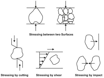
Fig. 14.18: Various methods of stress application in size reduction.
· — Stressing by the surrounding medium: Size reduction is effected by shear forces or pressure waves. The amount of energy that can be transferred is very limited, and this method is mainly used to break agglomerates.
Selection of the most suitable machine for a given requirement is an extremely complex process. The principle factors which must be addressed are the following.
· — Toughness/brittleness: In ductile materials the excess strain energy causes plastic deformation, whereas in brittle materials new cracks are propagated. Brittle materials can be reduced relatively easily, whereas ductile materials present challenges. It is sometimes possible to cool a tough material to a temperature low enough to display brittle behavior, as is sometimes done for grinding polymer granules and active pharmaceutical ingredients. The action of the cooling is to reduce the flexibility of the bonds joining the groups making up the polymer chains. It is often necessary to cool to very low temperatures, e.g. using liquid nitrogen (77 K = -196 °C).
· — Hardness: There are several hardness (qv) scales. In selecting size reduction equipment generally hardness is expressed according to the Mohs’ scale (Tab. 14.1), where a body in one range scratches a body in the immediately previous range. High-speed machines such as impact mills begin to suffer high wear rates when processing materials above Mohs’ hardness 3, unless very special wear-resisting measures can be taken.
Tab. 14.1: Mohs’ scale of hardness.
Mohs’ hardness |
Material |
1 |
Talcum |
2 |
Gypsum |
3 |
Calcite |
4 |
Fluorite |
5 |
Apatite |
6 |
Feldspar |
7 |
Quartz |
8 |
Topaz |
9 |
Corundum |
10 |
Diamond |
· — Abrasiveness: Abrasion is a special type of fracture responsible for the tearing out of small pieces of material from the surfaces of the components used to apply stress to the material being fractured. This property is closely related to hardness in homogeneous materials, but is also affected by particle shape, such as the presence of sharp corners. Although grinding components are designed strong enough to stress the material being comminuted without bulk fracture themselves, this is no guarantee that their surface will be abrasion resistant. The fracture mechanics of abrasion involves high local surface stresses owing to asperities in the particles and in the grinding surface. High rates of surface stressing in shears caused by high relative speed between stressing and stressed agents undoubtedly assist abrasive fracture.
· — Feed size: The acceptable feed size for a given machine is governed by the type of feed device and physical characteristics of the machine.
· — Cohesion: Many materials stick together and adhere to machine parts, depending on their composition, condition, particle size, and temperature.
· — Particle shape and structure: Some materials exhibit particular properties owing to their shape or form. It is often desired to maintain particle shape. In such cases an impact-type mill is usually preferred over a ball mill, as the latter tends to alter the original particle shape more strongly.
· — Heat sensitivity: Only maximimally 1-2 % of the applied energy is effectively used for size reduction. The remainder is mainly converted to heat, which is absorbed by the grinding air, product, and equipment. As a result materials can become sticky (e.g. fat-containing products), chemically degrade (active pharmaceutical ingredients, foods) or loose flavor.
14.3.3 Size-reduction equipment
A broad selection of different types of equipment is available as a result of the historical development and wide range of applications based on particle size, throughput, and material properties. No uniform criteria are available for classifying size-reduction equipment. The classification scheme used in this section is based on the method of stress application, particle size, and similarities between process types and machine construction.
Crushers
Crushers can process particles up to 1.5 m in edge length. Stress is applied by either crushing single particles or a bed of particles between two solid surfaces. Crushers are used in mines, for ore preparation and for the production of road construction materials. Most crushers are used for coarse and medium-size reduction to produce particles ready for transport, or to perform a primary reduction step prior to subsequent comminution. The principal requirement for crushers is a mechanical one: the machines must be very robust because of the high stresses required to crush a large lump. Crushers can be classified into four types: jaw crushers, gyratory crushers, impact crushers, and roll crushers.
Figs. 14.19 and 14.20 show examples of jaw and gyratory crushers, both of which compress the feed between a stationary and a movable surface. The reciprocating action of the movable jaw in a jaw crusher strains lumps of feed to the point of fracture, as does the nonsymmetric movement of the rotating mantle in a cone or gyratory crusher. The size reduction ratio is of the order of 10 and is varied by the adjustable gap setting. The basic action is that entering brittle material is crushed, the broken products fall under gravity into a narrower space, and bigger fragments are crushed as the metallump-metal space closes again, with material moving down until all of it falls through the gap. The crushing surfaces of jaw crushers are often ribbed or toothed, to help prevent slippage of the lumps/particles as they are compressed, and to give higher local stress at the surface of the material.
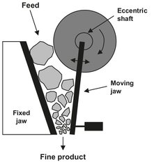
Fig. 14.19: Jaw crusher.
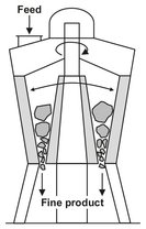
Fig. 14.20: Gyratory crusher.
Fig. 14.21 illustrates a hammer crusher. Material is broken by direct impact of the hammers, by being thrown against the case or breaker bars, and by compression and shear when nipped between the hammers and the case. The hammers are mounted on a heavy rotor and/or the shaft is attached to a heavy flywheel, to give high inertia of the rotating mass. In most cases the crushing zone is surrounded by grate bars, so that fragments which are larger than the openings of the grating are retained in the crushing zone. This type of crusher is best suited for soft and moderately hard nonabrasive but brittle materials. However, these crushers are simpler and therefore cheaper than jaw and cone crushers. Consequently, impact crushers have been developed for the processing of fairly abrasive rock that tend to wear out the machine.
Double roll crushers consist of two rollers, which rotate towards each other and are separated by an adjustable gap (Fig. 14.22). In a single roll crusher, a shaped crushing roller acts against a crushing plate. The material is fed in from above. The rollers, which often have a corrugated surface, draw in the feed and apply stress to it. The roller profile improves drawing in of the feed and therefore helps to increase the capacity. Because of abrasive wear the rolls have to be resurfaced at frequent intervals if the crushed material is strong and abrasive. With soft to moderately hard brittle materials, throughputs up to 3500 t/h may be obtained.
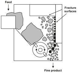
Fig. 14.21: Hammer crusher.
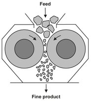
Fig. 14.22: Double roll crusher.
Grinding media mills
These mills consist of a vessel containing a moving grinding medium such as balls, rods, short bars, or course particle of the feed material itself. Tumbling ball mills, illustrated by Fig. 14.23, are very widely used for dry and wet grinding to relatively fine sizes. They have been utilized since the late 1800s, and the construction and principles remain essentially very simple. The machine consists of a cylindrical or conical tube into which loose grinding balls are filled up to a certain level. Size reduction is achieved by rotating the tube so that the balls roll against each other, or, if the speed is sufficient, they are lifted and fall. The grinding action ensures that a very high local stress can be applied to the particles so that a high portion of ultrafine product is produced.
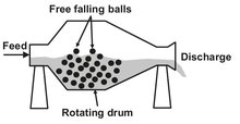
Fig. 14.23: Tumbling ball mill.
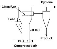
Fig. 14.24: Opposed jets fluid jet mill.
Roller and rod mills
In roller mills stress is applied to the feed in the gap between two oppositely rotating rollers. The design is equivalent to that of roll crushers. The rollers are typically 0.5-1.5 m in diameter and, in contrast to crushers, are smooth or grooved. The feed must have a narrow particle-size distribution to ensure that stress is not only applied to the coarsest particles in the mill gap. As a result of the mode of operation usually fine particle agglomerates are formed. They are employed in a wide variety of applications for medium-course down to fine size reduction, including the abrasives industry and the milling of cereals.
The rod mill acts in principle like a multiple set of rolls as the cylinder rotates. The bed of rods is carried up until it lies at an angle to the horizontal. It is then unstable, and rods start to roll down the bed surface. The rods rolling over one another act like sets of rolls, stressing particles in a similar manner. The power to the mill is used to lift the rods against gravity.
Jet and impact mills
In this group, stress is applied by transferring kinetic energy by either particle-particle contact (jet mills) or machine-particle contact (impact mills). In impact mills the particles fly against an impact plate or a rapidly moving grinding tool impacts slowly moving particles. Stress can also result from interparticle collisions. Stress application differs from that in previously described mills, where stress is primarily applied by means of pressure. The main differences between impacting and compression are that stress is applied to individual particles and that the velocity at which stress is applied is considerably higher. Very fine particles can be generated under dry conditions with impact and jet mills.
In jet mills the feed particles are accelerated by means of propellant jets (air, gas, or steam) with high velocities. Comminution occurs by interparticle collisions. These mills are always operated in closed circuit with an air classifier. Fig. 14.24 shows a drawing of an opposed jet mill in which the particles are accelerated through two or more pipes and directed against each other in the central grinding chamber. Because the working principle of jet mills is based on particle-particle collisions, jet mills are very suited for milling abrasive materials.
The range of products processed in impact mills is extraordinarily large. Impact mills are found in all branches of industry which deal with bulk materials or powders. Impact mill designs can be divided into beater mills, hammer mills, and mills with or without peripheral grinding faces. Hammer mills are basically similar to hammer crushers (Fig. 14.25). The hammers are usually simple iron plates and screen opening which surround the rotor range between 2 and 10 mm. The impact devices used in pin mills (Fig. 14.26) are large numbers of round pins or elongated squares. The devices are arranged in concentric rings of varying radii. The degree of fineness in a pin mill is determined primarily by the peripheral speed of the rotor. Because the number of collisions is relatively low, pin mills are well suited for temperature-sensitive or caking materials.
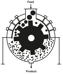
Fig. 14.25: Hammer mill.
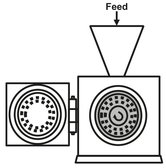
Fig. 14.26: Pin mill.
Cutting mills
Tough nonabrasive materials such as polymers, rubber, paper, and wood waste cannot be comminuted with any of the mills described so far. A whole class of mills are designed specifically for these applications. These rely on the cutting action between rotating and static sharp edges with narrow clearance. The efficiency of this type of mill is highly dependent on maintaining sharp cutting edges. Examples are shredders, chippers, knife-choppers, and pulp machines. The common design of these machines is to have a rotor equipped with several knife blades which cut the product against stationary knife bars.