Process Technology: An Introduction - Haan A.B. 2015
14 Solids finishing technologies
14.5 Conveying
14.5.1 Transportation systems
Conveying is a term used for the transport of bulk solids. The movement of bulk solids from one location in an industrial process operation to another has often been a source of considerable worry and expense. While gases and liquids can flow rather easily from one location to another, granular solids are much harder to transport. Conveyors are machines that transport material fed in a gravimetric or volumetric fashion in a controlled rate. By addition of appropriate weight sensing and control modules, conveyors can also be used as gravimetric feeders. The selection of the type of conveyor for a specific application is dependent on the
· (1) required capacity;
· (2) conveying path;
· (3) handling characteristics of the material.
The effective operation of most modern chemical manufacturing plants depends on the ability to move raw materials, semiprocessed, and fully-processed products, both within the manufacturing environment and ultimately to the end user.
Essentially two categories of bulk materials handling systems exist: direct and indirect transportation. The type of equipment can sometimes be suitable for both types of operation. The categorization of the transportation systems is illustrated in Fig. 14.36. Three of the most salient features for selecting a suitable handling system are knowledge of the distance, the required throughput, and the need for intermediate storage of the system. When specifying distance, details of the route profile are important: elevation, horizontal and vertical conditions to be traversed, head room, and route flexibility are critical issues for effective system selection. The handling system will often incorporate storage facilities, which also have to be carefully designed to meet a number of requirements.
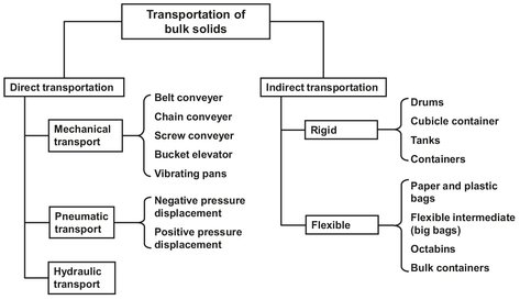
Fig. 14.36: Overview of solids transportation systems.
14.5.2 Mechanical conveyors
Mechanical conveying techniques are the most widely used form of materials handling in the chemical industry. Although a large number of devices are available, most systems conform to the basic elements in which either belts, chains, or moving flights are used to move material. Mechanical conveyors have distinct advantages in terms of the ability to effect accurate control in the monitoring of material from one process to another. Further it is possible to design systems to meet a wide variety of operating conditions, including corrosive environments and extremes of temperature.
Belt conveyors
A belt conveyor is made up of an endless fabric or elastomer-covered belt that traverses between two or more pulleys and is supported at intermediate points by idler rolls. These conveyors can handle a wide range of materials, from fine powders to large lumpy stone and coal. Large amounts (5000 t/h) of material can be transported over very long distances at lower cost than most other forms of conveying systems. Versatility, reliability, and range of capacities have made belt conveyors the most widely used mechanical conveying systems in the bulk solids industry. A typical belt conveyor arrangement is shown in Fig. 14.37. The belt conveyor system consists of several main components:
· — Belt. The belt consists of a carcass and a cover. Numerous forms of construction are used.
· — Idlers. Troughing idlers enable the belt load to be distributed and the belt volume and mass to be optimized.
· — Drive unit. The belt is driven by one drum at the turnaround side of the conveyor.
· — Loading and discharging. The belt is usually loaded by a gravity feeder such as a hopper, a preceding conveyor, or a vibratory feeder. Discharge of the bulk material is usually by gravity dumping.
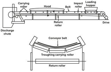
Fig. 14.37: Belt conveyor and support assembly.
· — Belt cleaners. This accessory to the belt conveyor is probably the most important. There are several types of belt cleaners designed to minimize the amount of carryover, increasing the life of the conveying system.
Belt conveyors can be arranged horizontally and with inclined or declined sections combined with convex and concave curves. The desired path of travel is limited only by the strength of the belt and the permissible angle of incline or decline for the particular situation.
Chain conveyors
A chain conveyor consists of an endless chain or cable pulling a series of spaced skeleton or solid plug flights through an enclosed casing or housing. Material is introduced through an opening in the casing, where it is captured by the flights and drawn through the casing, until it reaches an opening in the housing, where it is discharged by gravity. Some unique advantages of chain conveyors are compactness in cross section, totally enclosing of the bulk material, combining feeding, conveying, and elevating in one machine, and they can have multiple inlet and discharge openings.
Screw conveyors
A screw conveyor consists primarily of a rotating helicord placed in a stationary tubular— or U-shaped trough (Fig. 14.38). The helicord flight conveyor screw is made from a helix formed from a flat bar. This helix is then mounted on a pipe or round bar. As the screw rotates, material collects in front of the advancing flight and is pushed through the trough. Screw conveyors are of simple, relatively low cost construction and can handle a wide variety of solid particles ranging from lumps to powders within a completely enclosed housing. Conveying distances are limited by the torque capacity of available drive shafts. Power requirements are relatively high, and conveying efficiency is considerably reduced when screws are inclined or mounted vertically. There is a diverse number of uses for screw conveyors, such as controlled heating or cooling, mixing, and blending.
Vibrating conveyors Fig. 14.39 shows that a vibrating conveyor consists of a trough supported by tuned springs and/or hinged links which have a drive system. The oscillating movement of the vibratory conveyor accelerates the particles in both the horizontal and vertical directions, causing solid particles to be moved along the trough. These conveyors are ideally suited to the handling of granular, nonfree-flowing materials, and other materials which are awkward to handle. One of the biggest advantages of vibratory conveyors is that they can convey products such as sugar and milk powder under conditions that almost eliminate degradation. They are particularly suited for handling abrasive, hot, and dusty materials and can be designed to withstand heavy impact loads from materials such as rocks, iron, and steel castings. Equipment operates at frequencies ranging from 5 to 15 Hz, stroke range from 5 to 50 mm, and lengths of up to 50 m. There are two types of oscillating conveyors: reciprocating and vibrating.
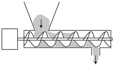
Fig. 14.38: Arrangement of a screw conveyor.
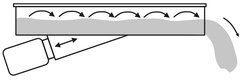
Fig. 14.39: Schematic of a vibrating conveyor.
On a reciprocating conveyor, material is carried forward in a horizontal direction by frictional contact with the trough. These conveyors are useful for handling granular free-flowing materials with a minimum of attrition. On a vibrating conveyor, material is moved along the trough in a series of hops. The particles are accelerated from the trough in an upward and forward trajectory as the trough moves forward. Because of its flexibility and ability to handle a wide range of materials the oscillating vibrating conveyor is the most commonly used type. Material must be fed onto a vibrating conveyor at a controlled rate. They are not designed for operation under a head load of solids in a storage silo or hopper. In addition to horizontal conveying, these conveyors can be used to perform other functions such as elevating, heating, drying, cooling, fluidization, agglomeration, screening, and dewatering.
Bucket elevators
Bucket elevators are the most commonly used device in the continuous unloading of ships, tankers, and other large storage depots. They consist of a series of buckets attached to an endless belt or chain that are filled with material and lifted vertically to a head pulley or sprocket, where the material is dumped. The buckets are then returned back down to a tail pulley or sprocket at the bottom. Bucket elevators are not self-feeding. They must be fed at a controlled rate to avoid overfilling the buckets and damaging the machinery. In the usual arrangement the chain or belt path is vertical or steeply inclined in a single plane. There are four broad classifications of bucket elevators: centrifugal, continuous, positive, and internal discharge. Centrifugal and continuous discharge elevators are by far the most commonly used. The centrifugaltype bucket elevator is used for free-flowing or granular products. The various elevator types are shown in Fig. 14.40. Bucket elevators have a distinct advantage over other high load conveyors in that they are completely maneuverable, simple, efficient, and reliable.
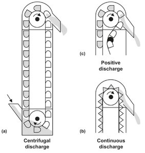
Fig. 14.40: Arrangement of bucket elevators: (a) centrifugal; (b) continuous; (c) positive.
14.5.3 Pneumatic conveying
Man has always recognized the ability of wind to move solid matter. Nowadays the pneumatic transport of solids represents the most widely used material handling techniques in the chemical industry. Of all the solids-moving equipment alternatives, pneumatic conveying is probably the most suitable method for the continuous transport of small-sized solids. A major advantage of pneumatic conveying is its extreme flexibility with regard to space design. As long as the conveying pipe is properly designed, the pneumatic conveyor can move the solids over, under, and around buildings, large equipment, and other obstructions. In comparison to other solids moving methods, pneumatic transport has a very decided advantage with regard to safety. Mechanical transport systems offer much potential for accidents and elaborate precautions must be taken for their safe operation.
In the past, the major disadvantage of pneumatic conveying has been the relatively high cost of power consumption compared to other bulk-solids-moving systems. However, nowadays these power costs have been reduced considerably and are counterbalanced by the steeply rising labor costs encountered with the other more manually operated solids-moving methods. At present, pneumatic conveying is applicable for relatively short distances, usually less than 4000 m. The type of material to be conveyed has a very great bearing on whether a gas-blown system can be utilized. Although pneumatic conveying can be used for many solids-conveying applications, these solids must be relatively dry and somewhat free flowing. In general, solids that are fragile and easily crumbled are not suitable for pneumatic conveying when breakage cannot be tolerated in the final product. Hygroscopic or agglomerating materials are not easily air-transported.
Classifications
Particle transport in pneumatic conveyors is commonly classified as either dilute phase or dense phase. As illustrated in Fig. 14.41, dilute phase flow is characterized by fully suspended flow in which all particles are moved along the pipe supported by the gas flow. When the solid-gas ratio is increased, the individual particles tend to settle at the bottom of the pipe and slide over other particles. This transition between dilute and dense-phase flow is known as the saltation point. Dense-phase flow is thus characterized by the solids moving as a bed along the bottom of the conveying pipe. When the particle segregation reaches a certain limit, the solids move from one dune to the next. Additional increases in the solid load can result in a slug flow, which is characterized by the intermittent flow of gas and solids in alternating slugs. An even higher solid-gas ratio may cause the solids to fill up a considerable portion of the pipe ultimately leading to complete blockage. These flow profiles are generally a function of the solids being conveyed.
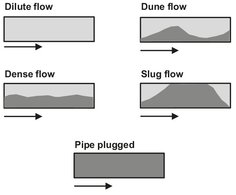
Fig. 14.41: Solid-gas flow patterns.
Dense-phase conveying is often called high-pressure, or low-velocity conveying. The term low-velocity conveying is quite descriptive, because typically velocities of around 10 m/s are used. Dense-phase systems have been used to transport up to 50 t/h and range from about 150—300 m in length. In general dense-phase flow, which employs far less conveying air, is more energy efficient than dilute-phase systems. Additional advantages over dilute-phase systems are a more gentle handling of materials and longer conveying distances. The added pressure requirements, however, dictate the need for more expensive high-pressure equipment. As a result dense-phase systems are at a cost disadvantage when multiple feed points are required, or when incremental compressed air for conveying is not available from existing sources.
Although the current trend is towards dense-phase conveying, the most popular pneumatic conveying systems still operate in the dilute-phase mode. Dilute-conveying systems operate as positive pressure systems at pressures up to 1 bar, or as negative pressure systems at pressures up to -0.5 bar. Typical flow air velocities are in the range of 25 m/s.
Pneumatic conveying systems
Certain basic components are required for a pneumatic conveying system. The solid product at atmospheric pressure must be fed into a flowing gas stream, conveyed over a prescribed route and, on reaching its destination, separated from the conveying gas. As illustrated by Fig. 14.42, a basic pneumatic conveying system consists of a prime mover such as blowers or compressors, the solids feeder, the conveying conduit system, and the solids-collecting equipment. The solids-feeding system is the most important item in any pneumatic conveying system. It must uniformly and continuously injects the solid particles into a positive or negative pressure gas stream. The conveyor lines must be designed so that the passage of solid-gas mixtures is relatively free of any flow-restricting regions where the solids might settle and stop moving, causing partial or complete flow plugs and blockages. The collection device must separate the solids from the gas medium as completely and efficiently as possible. Gas-solid separation systems vary from cyclone separators to highly sophisticated reverse jet bag filters.
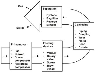
Fig. 14.42: Principle components of a pneumatic conveyingsystem.
There are two major classifications of pneumatic conveyors: vacuum and pressurized. The designation depends on whether the pressure within the conveyor is more or less than the outside pressure. In general the gas mover in the vacuum system is located behind the final solids collector, while with the pressurized conveyor the air blower is located in front of the equipment feeding the solids into the gas stream. A positive pressure system facilitates the feeding of the product into a positive pressure air stream. These systems are normally used to move solids from a fixed feeding location to multiple delivery points using a single pipeline and diverter valves to direct the flow. The positive-pressure conveyor equipment is usually arranged as shown in Fig. 14.43, with the feeder discharging the solids into a pressurized moving-gas stream. The major advantage of the pressurized system is the minimum amount of equipment required at the endpoint receiver.
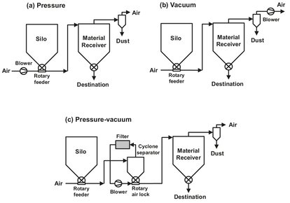
Fig. 14.43: Typical arrangements for pneumatic conveying systems.
Negative pressure (vacuum) systems are well suited to applications where product has to be picked up from several feed points and delivered to a single receiving point. This conveyor system, illustrated in Fig. 14.43, is composed of a gas intake and a mechanical solids feeder, a solids transport line, and a gas-solids separation device, followed by the gas mover. Vacuum systems are extensively used for the movement of toxic substances, where any hole in the pipeline would cause pollution problems. However, the lines should still be as leak-free as possible, since undesired air inlet flow requires a larger air blower capacity and can cause undesirable contamination of the solid product.
Nomenclature
A |
surface area |
[m2] |
H |
humidity |
[kg (kg dry)—1] |
Hrel |
relative humidity |
[%] |
ΔHv |
molar heat of evaporation |
[J mol—1] |
h |
heat transfer coefficient |
[W m—2 K—1] |
K |
Henry’s constant |
[bar kg m3] |
km |
mass transfer coefficient in a gas phase |
[ms—1] |
M |
molar weight |
[kg mol—1] |
p |
pressure |
[Pa] |
t |
time |
[s] |
T |
temperature |
[K] |
w |
weight |
[kg] |
x |
equilibrium dry basis moisture content |
[kg m—3] |